Table of Contents

Related Manuals for Emerson Rosemount 400


Summary of Contents for Emerson Rosemount 400
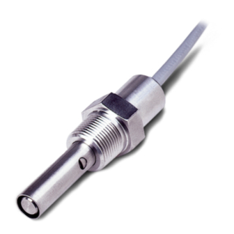
- Page 1 Instruction Manual LIQ-MAN-400 Rev. L May 2017 Rosemount 400 and 400VP ™ Contacting Conductivity Sensors...
- Page 2 hasgkas...
- Page 3 Essential Instructions Read this page before proceeding! Emerson designs, manufactures and tests its products to meet many national and international stan- dards. Because these sensors are sophisticated technical products, you MUST properly install, use, and maintain them to ensure they continue to operate within their normal specifications. The following instructions MUST be adhered to and integrated into your safety program when installing, using, and maintaining Rosemount products.
- Page 4 About This Document This manual contains instructions for installation and operation of the Rosemount 400 Contacting Conductivity Sensors. The following list provides concerning all revisions of this document. Rev. Level Date Notes 10/2016 Updated information with new Emerson Style Guidelines, Added Ordering Information, Added Accessories Information.
-
Page 5: Table Of Contents
Instruction Manual Table of Contents LIQ-MAN-400 May 2017 Contents Section 1: Specifications Specifications ......................1 Ordering Information...................2 Section 2: Installing the sensor ................3 Wiring the sensor....................5 Wiring the sensor to the transmitter ..............5 Section 3: Calibration and Maintenance Calibrating the sensor ..................9 Cleaning the sensor ...................12 Section 4: Troubleshooting Troubleshooting ....................13... - Page 6 Table of Contents Instruction Manual May 2017 LIQ-MAN-400 Table of Contents...
-
Page 7: Section 1: Specifications
Instruction Manual Specifications LIQ-MAN-400 May 2017 Section 1: Specifications Specifications Table 1-1 Rosemount 400/400VP contacting conductivity sensor specifications Wetted materials Electrodes Titanium Insulator Glass Filled PEEK Body 316 Stainless Steel O-ring EPDM Temperature range Standard 32 to 221 °F (0 to 105 °C) With Optional Integral Junction Box 32 to 392 °F (0 to 200 °C) -
Page 8: Ordering Information
Specifications Instruction Manual May 2017 LIQ-MAN-400 Ordering Information Table 1-3 Rosemount 400 Contacting Conductivity Sensor ordering information Model Sensor type Contacting Conductivity Sensor Cell constant 0.01/cm 0.1/cm 1.0/cm Temperature compensation Pt-1000 Pt-100 10K Ohm TC Option 1 No selection Extended insertion length... -
Page 9: Section 2: Installing The Sensor
Conductivity Sensors with 0.1 and 1.0/cm cell constants can be installed in ¾-inch pipe tees. Rosemount 400/400VP Contacting Conductivity Sensors can be installed in 1-inch tees with a ¾-inch bushing. If the sensor is installed in a pipe tee or flow cell with the sample draining to open atmosphere, bubbles may accumulate on the electrodes. - Page 10 Installation Instruction Manual May 2017 LIQ-MAN-400 Figure 2-7 Rosemount 400 with integral cable connection dimensional drawing Sensor c onfiguration Millimeter Inches Inches mm Inches Inch 0.01/cm 1.59 40.39 1.98 50.34 4.52 114.8 0.1/cm 0.687 17.45 1.11 28.15 3.65 92.71 1.0/cm 0.667...
-
Page 11: Wiring The Sensor
Instruction Manual Installation LIQ-MAN-400 May 2017 Wiring the sensor For other wiring diagrams not shown below, please refer to the Liquid Transmitter Wiring Diagrams. Table 2-1 Wire color and connections in sensor Color Function Gray Connects to outer electrode Clear Coaxial shield for gray wire Orange Connects to inner electrode... - Page 12 Installation Instruction Manual May 2017 LIQ-MAN-400 Figure 2-11 Wiring for Rosemount 1066 transmitter WHITE RCV B SENSE WHITE/RED RCV A RTD IN CLEAR RSHLD SHLD CLEAR GRAY DRVB ORANGE DRVA CLEAR DSHLD Figure 2-12 Wiring for Rosemount 5081 transmitter Installation...
- Page 13 LIQ-MAN-400 May 2017 2.2.1 Wiring through junction box Rosemount 400 Contacting Conductivity Sensors can have an optional integral junction box mounted on the end of the sensor. See Figure 2-13 for wiring instructions. If wiring connections are made through a remote junction box (PN 23550-00), wire point-to-point.
- Page 14 Installation Instruction Manual May 2017 LIQ-MAN-400 Figure 2-14 Pin out diagram for Rosemount 400VP Contacting Conductivity Sensor with Variopol cable connection Installation...
-
Page 15: Section 3: Calibration And Maintenance
Section 3: Calibration and maintenance Calibrating the sensor Rosemount 400/400VP Contacting Conductivity Sensors are calibrated at the factory and do not need calibration when first placed in service. Simply enter the cell constant printed on the label into the transmitter. After a period of service, the sensor may require calibration. For more... - Page 16 Calibration and Maintenance Instruction Manual May 2017 LIQ-MAN-400 3.1.2 Calibrating using a reference meter and sensor Connect the process sensors and reference sensor in series and allow the process liquid to flow through all sensors. Calibrate the process sensor by adjusting the process transmitter reading to match the conductivity measured by the reference meter.
- Page 17 Instruction Manual Calibration and Maintenance LIQ-MAN-400 May 2017 Orient the sensors so that air bubbles always have an easy escape path and cannot get trapped between the electrodes. Turn off automatic temperature compensation in the transmitter. Almost all process conductivity transmitter feature automatic temperature compensation in which the transmitter applies one of several temperature correction algorithms to convert the measured conductivity to the value at a reference temperature, typically 25 °C.
-
Page 18: Cleaning The Sensor
Calibration and Maintenance Instruction Manual May 2017 LIQ-MAN-400 Grab sample calibration should be used only when the conductivity is fairly high. a. The temperature compensation algorithm will most likely be linear slope. b. Confirm that both instruments are using the same temperature coefficient in the linear slope calculation. -
Page 19: Section 4: Troubleshooting
Instruction Manual Troubleshooting LIQ-MAN-400 May 2017 Section 4: Troubleshooting Troubleshooting Problem Probable Cause Solution Wiring is wrong. Verify wiring. Temperature element is open or shorted. Check temperature element for open or short circuits. Figure 4-1 Sensor is not in process stream. Be sure sensor is completely submerged in process Off-Scale Reading stream. - Page 20 Troubleshooting Instruction Manual May 2017 LIQ-MAN-400 4.1.1 Checking the temperature element Disconnect leads and measure resistance shown. The measured resistance should be close to the value in the table. Figure 4-1 Checking the temperature element Temperature Resistance in ohms (°C) Pt 100 Pt 1000 100.0...
-
Page 21: Section 5: Accessories
Instruction Manual Accessories LIQ-MAN-400 May 2017 Section 5: Accessories Accessories Table 5-1 Rosemount 400/400VP Contacting Conductivity Sensor accessories information Part Number Description 23550-00 Remote junction box without preamplifier 23747-00 Interconnect cable, prepped (must specify length) 9200275 Extension cable, unprepped (must specify length) - Page 22 ©2017 Emerson Automation Solutions. All rights reserved. Chanhassen, MN 55317, The Emerson logo is a trademark and service mark of Emerson Electric Co. Rosemount is a mark of one of the Emerson family of companies. All other marks are the property of their respective Tel +1 800 999 9307 owners.