
Related Manuals for Siemens FDUL221


Summary of Contents for Siemens FDUL221
- Page 1 FDUL221 Line tester Technical Manual Building Technologies 008250_i_en_-- 2013-08-15 Control Products and Systems...
- Page 2 Legal notice Technical specifications and availability subject to change without notice. © 2005-2013 Copyright by Siemens Switzerland Ltd Transmittal, reproduction, dissemination and/or editing of this document as well as utilization of its contents and communication thereof to others without express authorization are prohibited.
-
Page 3: Table Of Contents
Table of contents About this document ..................5 Technical terms ....................7 Applicable documents ..................7 History of changes ....................8 Safety ......................11 Safety instructions ..................11 Safety regulations for the method of operation ..........13 Standards and directives complied with ............14 Comparison of software functions .............. - Page 4 Error search using the 'bisection' method ......... 61 6.14.2 Error search using the 'measure line device' method ......62 6.14.3 Explanation of ground fault measurement (for FDUL221 variant 3 only) ....................63 Maintenance / Repair ..................64 Testing the line tester ..................64 7.1.1...
-
Page 5: About This Document
Three variants of the FDUL221 line tester are described. Variant 1 (RS232) applies to FDUL221 with an RS232 serial interface Variant 2 (MC link) applies to FDUL221 with an MC link serial interface Variant 3 (USB interface) applies to FDUL221 with an integrated USB interface Following the instructions consistently will ensure that the product can be used safely and without any problems. -
Page 6: Date Format
About this document Technical terms Conventions for text marking Markups Special markups are shown in this document as follows: Requirement for a behavior instruction Intermediate result of a behavior instruction End result of a behavior instruction Reference to a page number 'Text' Quotation, reproduced identically... -
Page 7: Technical Terms
Variant 1 (RS232) FDUL221 with RS232 interface No. A5Q00004397 Variant 2 (MC link) FDUL221 with 3.5 mm socket No. A5Q00022100 Variant 3 (USB interface) FDUL221 with USB interface No. A5Q00055304 1.2 Applicable documents Document ID Title 008331 List of compatibility (for 'Sinteso™' product line) -
Page 8: History Of Changes
About this document History of changes 1.3 History of changes The reference document's modification index applies to all languages into which the reference document is translated. The first edition of a language version or a country variant may, for example, have the modification index 'd' instead of 'a' if the reference document already has this modification index. - Page 9 About this document History of changes Modification index Edition date Brief description Menu trees for 'EL' operation mode Text changes in 'The 'device' function' chapter Text amended in the 'Connecting the line tester to the line' chapter, new figures added Text amended in the 'Switching the line tester on and off' chapter, 'Switching on for configuration' added, new figures added Text changed in the 'Configuring the line tester' chapter...
- Page 10 About this document History of changes The language versions and country variants produced by a local company have the same modification index as the corresponding reference document. They are not however included in the table below. The table below shows the published language versions with the corresponding modification index: Modification index en_--...
-
Page 11: Safety
Safety Safety instructions 2 Safety 2.1 Safety instructions The safety notices must be observed in order to protect people and property. The safety notices in this document contain the following elements: Symbol for danger Signal word Nature and origin of the danger Consequences if the danger occurs Measures or prohibitions for danger avoidance Symbol for danger... - Page 12 Safety Safety instructions Signal word The signal word classifies the danger as defined in the following table: Signal word Danger level DANGER DANGER identifies a dangerous situation, which will result directly in death or serious injury if you do not avoid this situation. WARNING WARNING identifies a dangerous situation, which may result in death or serious injury if you do not avoid this situation.
-
Page 13: Safety Regulations For The Method Of Operation
2.2 Safety regulations for the method of operation National standards, regulations and legislation Siemens products are developed and produced in compliance with the relevant European and international safety standards. Should additional national or local safety standards or legislation concerning the planning, assembly, installation,... -
Page 14: Standards And Directives Complied With
Personal injury or damage to property caused by poor maintenance or lack of maintenance 2.3 Standards and directives complied with A list of the standards and directives complied with is available from your Siemens contact. Building Technologies 008250_i_en_--... -
Page 15: Comparison Of Software Functions
Comparison of software functions 3 Comparison of software functions The table below displays the main differences in terms of functionality for the following software: Line tester FDUL221 FDUL221 line tester in 'EL' operation mode 'PC Linetester Tool FXS2017' software FDUL221 FDUL221-EL FXS2017... - Page 16 Export function of the read-in topologies, e.g. to be able to keep a record of installed devices. *Possible with firmware version V4.x.x or higher Function available __ Function not available FDUL221 Standard FDUL221-EL 'EL' operation mode FXS2017 'PC Linetester Tool FXS2017' software Building Technologies 008250_i_en_-- Fire Safety...
-
Page 17: Introduction
Introduction Line topologies 4 Introduction The basics of detector lines are described below. An understanding of the basics is a prerequisite for operating the FDUL221 line tester. 4.1 Line topologies In the FDnet/C-NET, the following topologies are admissible. Loop Stub... -
Page 18: Technical Specifications
Introduction Line topologies Technical specifications All FDnet/C-NET devices have an integrated line separator. Only one stub may branch off between two adjacent line devices. When there are several stubs next to one another, a line separator FDCL221 must be connected between each one. Maximum number of stubs/loops: Max. -
Page 19: Line Separation Function
Introduction Line separation function 4.2 Line separation function All FDnet/C-NET devices have an integrated line separator. It has two functions: Short-circuit and open line monitoring Allows branching of stubs between two FDnet/C-NET devices Short-circuit monitoring In the case of a short-circuit on the detector line, the line separator automatically isolates the faulty line section. -
Page 20: Structure And Function
If a line device is connected or removed later, the line topology previously read in is not updated automatically. The FDUL221 line tester can be operated independently or with the ’PC Linetester Tool FXS2017’ software. Features of the FDUL221 line tester... - Page 21 Structure and function Overview Fields of application Addressed detector line (FDnet/C-NET) Recognition of the FDnet/C-NET devices Recognition of the line topology Error search and diagnosis Installation (control and acceptance) Interface between FDnet/C-NET and PC Building Technologies 008250_i_en_-- Fire Safety 2013-08-15...
- Page 22 Structure and function Overview Connections to the detector line and PC The following figure shows the connection between the FDUL221 and the PC for different variants of the FDUL221 line tester. Variant 3 FDUL221 POW ER DC IN 2 4 V...
- Page 23 Graphical representation of the line Display detailed information about the devices The 'PC Linetester Tool FXS2017' software is supplied on a CD with the FDUL221 line tester or can be downloaded from the Intranet obtain from: Customer Support Center/PSP Product Support Platform CSC address: https://intranet.sbt.siemens.com/fs/CSC/...
- Page 24 Overview 'EL' operation mode The FDUL221 line tester can be used in 'EL' operation mode by electricians. In the 'EL' operation mode, detector lines can be read in, checked and saved. To change the operation mode, a firmware update must be carried out on the FDUL221 line tester [ 69].
-
Page 25: Details For Ordering / Scope Of Delivery
5.1.1 Details for ordering / scope of delivery With the order number A5Q00004397, the latest variant of the FDUL221 line tester is always supplied with the stated scope of delivery. Details for ordering and scope of delivery for variant 3 (USB) with... - Page 26 Line tester, complete FDUL221 A5Q00004397 FDUL221 line tester with RS232 connection (A5Q00004397) FDUL221-A line connection kit FDUL221-B power unit kit (network adapter for power supply) FDUL221-C PC cable (RS232) FDUL221-D PC software on CD – Software: 'PC Linetester Tool FXS2017' –...
-
Page 27: Product Version Es
Structure and function Overview 5.1.2 Product version ES The product version ES provides the technical status of a device in terms of software and hardware. The product version is provided as a two-digit number. You will find the details of your device's product version: On the packaging label On the product label or the type plate Product version on the packaging label... -
Page 28: Setup
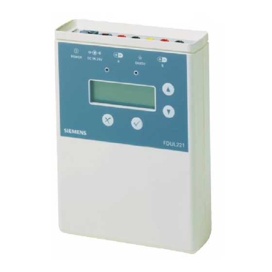
Structure and function Setup 5.2 Setup The FDUL221 line tester is built in a plastic housing. The power is supplied by batteries or with the FDUL221-B power unit. Setup Item Symbol/ Description Function Element Display Adjustable backlight and contrast Scrolling plain text and symbol display... -
Page 29: Display
B testers also RS232 interface or MC link) 5.2.1 Display The FDUL221 line tester has a 4-line display with 20 characters per line. Features Adjustable backlight Adjustable contrast Automatic adjustment of the vertical and horizontal scroll function with the... -
Page 30: Symbols
Structure and function Setup 5.2.2 Symbols The table below lists the displayed symbols and their meaning. Symbol Meaning Battery operation The level shown in the symbol indicates the charge state of the partially discharged batteries Example: Symbol on left for low battery charge state Symbol on right for high battery charge state External power supply (mains operation) Cursor position displays... -
Page 31: Led Indication
Structure and function Setup 5.2.3 LED indication The LEDs indicate the operating condition of the FDUL221 line tester. Element Description Function Flashes slowly Error when starting up the FDUL221 line tester LED red Flashes rapidly Connection to PC, e.g. download... -
Page 32: Connections
Structure and function Setup 5.2.5 Connections Connection for external power supply For the power supply, only connect the FDUL221-B power unit kit to the socket. USB connection to the PC Connect the USB cable to the socket to connect to the PC. - Page 33 NOTICE Connecting the FDUL221 line tester incorrectly may damage the hardware. Connecting the fire detection installation and the FDUL221 line tester to the detector line at the same time can result in irreparable damage to the line interface or the FDUL221 line tester.
-
Page 34: Connection To Terminal Strip
The feed line for the detector line is directly connected to the terminal strip. The terminal strip, measurement line and the terminal plug are available. 1. Connect the terminal strip to the sockets on the FDUL221. Terminal no. 1 is connected to socket A(+) with the terminal plug (red). -
Page 35: Battery Compartment
Structure and function Setup 5.2.7 Battery compartment The battery compartment is on the underside of the FDUL221 line tester. It is shut with a removable cover. Battery compartment 1 Opened battery compartment with symbol indicating the correct location for the two batteries... -
Page 36: Accessories
Compatible with: – Radio gateway FDCW221 – DOW1171 radio smoke detector – Radio test set DZW1171 – Line tester FDUL221 – Detector exchanger and tester FDUD292 – Intelligent detector tester FDUD293 Order no.: A5Q00004142 5.3.2 MCL-USB adapter FDUZ221 For connecting FDnet/C-NET devices to a personal... -
Page 37: Function
The batteries may be inserted during mains operation. For mains operation, connect the FDUL221-B power unit to the socket for external power supply. The mains operation is shown as a symbol in the display when the FDUL221 is switched on. Mains operation Battery operation For battery operation, insert two batteries into the battery compartment. -
Page 38: El' Operation Mode
5.4.3 'EL' operation mode The FDUL221 line tester can be used in 'EL' operation mode. The 'EL' operation mode is only intended for use by electricians. In 'EL' operation mode, the detector lines can be read in, checked and saved. -
Page 39: Functions In The 'Configuration' Menu
Navigating in the menu tree [ 5.4.6 PC operation The FDUL221 line tester can communicate with a PC via cable for the following tasks: Firmware update for the FDUL221 line tester Transferring data from the FDUL221 line tester to a PC... -
Page 40: Operation
For a loop or a sub-stub on a loop, select 'Startup Loop A->B'. For a stub or a single line device, select 'Startup Stub A'. 4. Exit the 'Topology' menu tree by switching the FDUL221 line tester off. Building Technologies... - Page 41 Operation Navigating in the menu tree Version ... FDnet ..FDUL221 Startup Loop A->B Startup Stub A Convert Line Also read in the sub-stub on the loop Startup Loop A->B Startup Line Startup Stub A Devices Startup Line Loop Start...
- Page 42 Navigating in the menu tree 'Configuration' menu tree 1. To navigate in the 'Configuration' menu tree, press the button and switch the FDUL221 line tester on at the same time. The display shows 'LineTester Config'. 2. Use the buttons to navigate.
-
Page 43: Menu Trees For 'El' Operation Mode
Navigating in the menu tree 6.1.1 Menu trees for 'EL' operation mode 1. To navigate in the 'Topology' menu tree, switch the FDUL221 line tester on. 2. To navigate in the 'Configuration' menu tree, press the button and switch the FDUL221 line tester on at the same time. - Page 44 Operation Navigating in the menu tree Topology Configuration Version ... LineTester Config FDnet ..Memory Usage:. 'EL' operation mode FDUL221-EL ..LCD setup ....Also read in the sub-stub on the loop Contrast Startup Loop A->B Light mode Startup Line...
-
Page 45: The 'Device' Function
In the case of the FC20xx, FC72x or AlgoRex fire control panels, the inputs of a FDCIO222 that are not used (= not linked) are directly set to 'off' in the line device. The input status of the FDUL221 line tester is therefore not displayed. Meaning of inputs The display depends on the line device connected. - Page 46 Operation The 'device' function Assignment of outputs The assignment of the outputs A, B, C, D depends on the line device. Line device Output A Output B Output C Output D Notes Point detector (thermal Ext. AI Activation of Activation of alarm / optical) evacuation signal signal...
-
Page 47: Connecting The Line Tester To The Line
3. To detect shielding errors, connect the shielding to the ground wire. For a loop: 1. Connect both ends of the line to the FDUL221 line tester. 2. Connect the ends of the feed line to line 'A'. 3. Connect the ends of the return line to line 'B'. - Page 48 The feed line for the detector line is directly connected to the terminal strip. The terminal strip, measurement line and the terminal plug are available. 1. Connect the terminal strip to the sockets on the FDUL221 line tester. Terminal no. 1 is connected to socket A(+) with the terminal plug (red).
-
Page 49: Switching The Line Tester On / Off
The FDUL221 line tester is in the ’Configuration’ menu. Switching off Move the switch into position. The indicator goes out. If working with the FDUL221-B power unit, the power unit can be removed. See also Setup [ Building Technologies 008250_i_en_--... -
Page 50: Configuring The Line Tester
Configuring the line tester 6.5 Configuring the line tester The FDUL221 line tester must be set to the relevant protocol if it is being used on a detector line. The protocol is permanently set in the 'EL' operation mode and cannot be configured. -
Page 51: Reading In Line Topology
To read in the line topology, proceed as follows: 1. Disconnect the detector line or the line section from the control panel. 2. Connect the FDUL221 line tester to the detector line or line section. Adhere to the polarity [ 47]. -
Page 52: Loop
Operation Viewing line topology 6.7.1 Loop The 'loop' topology is permitted. Detector line on the control panel Arrangement of the line devices Display The line devices are displayed in the order of the loop. The display shows the number of the line device in brackets. E.g. [T001] for the first line device. In the case of the red outlined device, the internal alarm indicator flashes. -
Page 53: Sub-Stub On Loop
Operation Viewing line topology 6.7.3 Sub-stub on loop The 'sub-stub on loop' topology is permitted. Detector line on the control panel Arrangement of the line devices Display The line devices are displayed in the order of the loop. On the branch to the sub- stub, the line devices are displayed in the order of the sub-stub. -
Page 54: Impermissible Sub-Stubs
Operation Starting up a line 6.7.4 Impermissible sub-stubs The following sub-stubs are not permitted: Sub-stub on stub Sub-stub on loop without line separation Sub-stub on sub-stub on loop Detector line on the control panel Arrangement of the line devices Display The line devices are displayed in the order of the loop/stub. -
Page 55: Saving A Line Topology
8. Press the button. The line topology is saved. The topologies saved on the FDUL221 line tester can be transferred to a PC using the 'PC Linetester Tool FXS2017' software. See also Transferring a saved line topology to a PC [... -
Page 56: Opening A Saved Line Topology
Operating the line tester with a PC The FDUL221 line tester can be controlled via a connected PC. The 'PC Linetester Tool FXS2017' software is supplied with the FDUL221 line tester on CD or can be downloaded from the Customer Support Center... -
Page 57: Transferring A Saved Line Topology To A Pc
The line tester can be operated from the PC using the 'PC Linetester Tool FXS2017' software. You can delete all the files on the FDUL221 line tester with the 'PC Linetester Tool FXS2017' software. The USB connection can be affected in areas where there is a high level of EMC interference. -
Page 58: Table Of Faults
Table of faults 6.13 Table of faults Below you will find an overview of the errors displayed by the FDUL221 line tester as well as possible causes and remedies for the errors. Line device Line device is shown on the display, the internal and external alarm indicators flash... - Page 59 The exact position of the error cannot Find the faulty location by separating the parts of the detector line and checking the separated be identified by the FDUL221 line tester. line parts (e.g. ½, ¼, ). Also refer to the tips on 'Error search' [ 61].
- Page 60 Operation Table of faults Error display Possible cause Remedy E13 bad EOS Error on the last line device of a stub: In the case of a In the case of migrated lines: Check whether a closed line separator, an increased load current is detected resistor or a Z diode is still installed on the line on this line device.
-
Page 61: Tips For Troubleshooting On The Detector Line
Shield fault Shield permeability Shield ground fault If a single line device is selected with the FDUL221 line tester, its internal or external alarm indicator will flash. If the 'All ON' is selected in the 'Locate devices' menu, the internal/external alarm indicators of all line devices detected by the FDUL221 line tester flash. -
Page 62: Error Search Using The 'Measure Line Device' Method
Operation Tips for troubleshooting on the detector line 6.14.2 Error search using the 'measure line device' method Recommended for errors E02, E14, E15. Using the measured value you can determine whether the error lies upstream or downstream of the selected line device. -
Page 63: Explanation Of Ground Fault Measurement (For Fdul221 Variant 3 Only)
100 k on account of the internal circuit. A resistance to ground that exceeds 500 k can no longer be reliably detected. If the line is measured manually using a multimeter, the line must be disconnected from the FDUL221 line tester. Building Technologies 008250_i_en_--... -
Page 64: Maintenance / Repair
Testing the line tester 7 Maintenance / Repair 7.1 Testing the line tester The FDUL221 line tester is set in the factory. This setting cannot be changed by the user. During the selftest the settings are tested automatically, by electronically connecting and measuring reference resistances in the different configuration. - Page 65 Maintenance / Repair Testing the line tester Internal HW – 'Test Hardware' Linedriver – 'Test Linedriver A(+)' Cablin/Fuse A(+) – 'Connect EARTH to A(+)' Cablin/Fuse A(-) – 'Connect EARTH to A(-)' Cablin/Fuse B(+) – 'Connect EARTH to B(+)' Cablin/Fuse B(-) –...
-
Page 66: Testing Calibration
Maintenance / Repair Testing the line tester 7.1.2 Testing calibration If testing manually, use a digital voltmeter with 'True RMS'. The table below shows the nominal measured value as a function of the configured control unit. Control panel Mode Nominal measured value FS20 FDnet 32 V DC 28 V ±... -
Page 67: Replacing Batteries
Replacing batteries 7.2 Replacing batteries The charge state of the batteries is indicated on the right of the FDUL221 line tester's display. To ensure the faultless functionality of the FDUL221 line tester, weak batteries must be replaced by new ones. -
Page 68: Service Life Of The Batteries
Maintenance / Repair Replacing batteries 7.2.1 Service life of the batteries The service life strongly depends on the line allocation, the display light and the operating temperature. Operation mode Service life at room temperature Lighting ON Lighting OFF Normal operation (quiescent Approx. -
Page 69: Firmware Update
When a firmware update is carried out, the new firmware overwrites the old firmware. To carry out a firmware update, the components for connecting the PC with the FDUL221 line tester must be available. You will find more information in chapter 'Operating the line tester with a PC [ 56]'. - Page 70 Maintenance / Repair Firmware update Firmware update by PC Permanent and safe power supply to the FDUL221 line tester is available while the update is taking place. The file required for the firmware update is available. You will find the file on the CD included in the set or on the Intranet in the Customer Support Center 1.
-
Page 71: Specifications
Specifications Technical data 8 Specifications 8.1 Technical data The following data only applies to the FDUL221 line tester, variant 3. Power supply Operating voltage: DC 10…30 V Battery 2 x lithium manganese dioxide type U9VL Li/MnO2 9 V, 1 Ah... - Page 72 -25…+40 °C (LCD 0…+40 °C) Storage temperature without battery -30…+75 °C Storage temperature with battery -25…+60 °C Air humidity (non-condensing) 95 % rel. Protection category for FDUL221 IP30 Protection category for network adapter IP41 Test class 4 kV Standards European standards...
-
Page 73: Environmental Compatibility And Disposal
Specifications Environmental compatibility and disposal 8.2 Environmental compatibility and disposal This device is manufactured using materials and procedures which comply with current environmental protection standards as best as possible. More specifically, the following measures have been undertaken: Use of reusable materials Use of halogen-free plastics Electronic parts and synthetic materials can be separated Larger plastic parts are labeled according to ISO 11469 and ISO 1043. -
Page 74: Index
Replacing batteries, 67 Tips for troubleshooting on the detector line, 61 Service life of the batteries, 68 FDCL221 line separator, 19 FDUZ221/FDUZ227 Connections Connect to PC and FDUL221, 56 Bushes, 28 Firmware update, 69 Control panel Fuses Configure on control panel, 50... - Page 75 Index Operation mode Changing the operation mode, 38 'EL' operation mode, 24 Packaging label Product version, 27 Product label Product version, 27 Recycling, 73 RS232 Cables, 26 Product version, 5 Selftest, 64 Stub Connections, 32, 47 Read in, 51 Topology, 17 Viewing stub, 52 Sub-stub Impermissible sub-stubs, 54...
- Page 76 Issued by © 2005-2013 Copyright Siemens Switzerland Ltd Siemens Switzerland Ltd Technical specifications and availability subject to change without notice. Infrastructure & Cities Sector Building Technologies Division International Headquarters Gubelstrasse 22 CH-6301 Zug Tel. +41 41-724 24 24 www.siemens.com/buildingtechnologies Document ID...