
Related Manuals for Mitsubishi Electric HG-MR


Summary of Contents for Mitsubishi Electric HG-MR
- Page 1 General-Purpose AC Servo MODEL HG-MR HG-KR HG-SR HG-JR HG-RR HG-UR HG-AK SERVO MOTOR INSTRUCTION MANUAL (Vol. 3)
- Page 2 Safety Instructions Please read the instructions carefully before using the equipment. Do not attempt to install, operate, maintain or inspect the equipment until you have read through this Instruction Manual and appended documents carefully and can use the equipment correctly. Do not use the equipment until you have a full knowledge of the equipment, safety information and instructions.
- Page 3 1. To prevent electric shock, note the following WARNING Before wiring and inspections, turn off the power and wait for 15 minutes or more (20 minutes or more for converter unit and drive unit) until the charge lamp turns off. Then, confirm that the voltage between P+ and N- (L+ and L- for converter unit and drive unit) is safe with a voltage tester and others.
- Page 4 4. Additional instructions The following instructions should also be fully noted. Incorrect handling may cause a malfunction, injury, electric shock, fire, etc. (1) Transportation and installation CAUTION Transport the products correctly according to their mass. Use the eyebolt of the servo motor for the transportation purpose only. Do not use the eyebolts to transport the servo motor when it is mounted on a machine.
- Page 5 10 %RH to 90 %RH (non-condensing) Indoors (no direct sunlight), free from corrosive Ambience gas, flammable gas, oil mist, dust, and dirt Altitude Max. 2000 m above sea level (Note 2) HG-MR Series/HG-KR Series/HG-AK Series X, Y: 49 m/s HG-SR51/HG-SR81/HG-SR52(4)/ HG-SR102(4)/HG-SR152(4)/HG-JR53(4)/ HG-JR73(4)/HG-JR103(4)/HG-JR153(4)/ HG-JR203(4)/HG-JR353(4)/HG-JR503(4)/ HG-JR701M(4)/HG-JR11K1M(4)/ X, Y: 24.5 m/s...
- Page 6 CAUTION Do not connect AC power supply directly to the servo motor. Otherwise, it may cause a malfunction. When the cable is not tightened enough to the terminal block, the cable or terminal block may generate heat because of the poor contact. Be sure to tighten the cable with specified torque. (3) Test run and adjustment CAUTION Before operation, check the parameter settings.
- Page 7 (5) Corrective actions CAUTION Ensure safety by confirming the power off, etc. before performing corrective actions. Otherwise, it may cause an accident. When it is assumed that a hazardous condition may occur due to a power failure or product malfunction, use a servo motor with an electromagnetic brake or external brake to prevent the condition.
- Page 8 DISPOSAL OF WASTE Please dispose a servo motor and other options according to your local laws and regulations. «U.S. customary units» U.S. customary units are not shown in this manual. Convert the values if necessary according to the following table. Quantity SI (metric) unit U.S.
- Page 9 MEMO A - 8...
-
Page 10: Table Of Contents
4- 1 to 4-26 4.1 Connection instructions ........................4- 2 4.2 Wiring ..............................4- 3 4.2.1 HG-MR series/HG-KR series servo motor ................. 4- 3 4.2.2 HG-SR series/HG-JR series/HG-RR series/HG-UR series servo motor ........4- 8 4.2.3 HG-AK series servo motor ......................4-14 4.3 Selection example of wires ...................... -
Page 11: Table Of Contents
5.5 Electromagnetic brake cable ......................5-30 5.6 Wires for option cables ........................5-32 6. HG-MR SERIES/HG-KR SERIES 6- 1 to 6-60 6.1 Model code definition ........................6- 1 6.2 Combination list of servo motors and servo amplifiers ..............6- 2 6.3 Standard specifications ........................ -
Page 12: Table Of Contents
7.7.6 For general industrial machine with a reducer (foot-mounting/with an electromagnetic brake) ......................7-60 7.7.7 With flange-output type reducer for high precision applications, flange mounting (without an electromagnetic brake) ......................7-71 7.7.8 With flange-output type reducer for high precision applications, flange mounting (with an electromagnetic brake) ...................... -
Page 13: Table Of Contents
10.7 Dimensions ........................... 10- 7 10.7.1 Standard (without an electromagnetic brake) ................ 10- 7 10.7.2 With an electromagnetic brake ....................10- 9 11. HG-AK SERIES 11- 1 to 11-14 11.1 Model designation ......................... 11- 1 11.2 Combination list of servo motors and servo amplifiers ..............11- 1 11.3 Standard specifications ......................... -
Page 14: Rating Plate
1. INTRODUCTION 1. INTRODUCTION 1.1 Rating plate The following shows an example of rating plate for explanation of each item. (1) HG-MR/HG-KR/HG-SR/HG-JR/HG-RR/HG-UR series servo motor Model (Note 2) Input power, rated current, rated output MSIP-REI-MEK-BSM0010000000A Mass, insulation class Rated speed... - Page 15 1. INTRODUCTION (3) HG-AK series servo motor (Note 2) Model Input power, rated output Serial number (Note 1) Rated speed Mass Country of origin, conforming standards Manufacturer Note. Production year and month of the servo motor are indicated in a serial number on the rating plate. The year and month of manufacture are indicated by the last two digits of the year and one digit of the month [1 to 9, X (10), Y (11), and Z (12)].
-
Page 16: Parts Identification
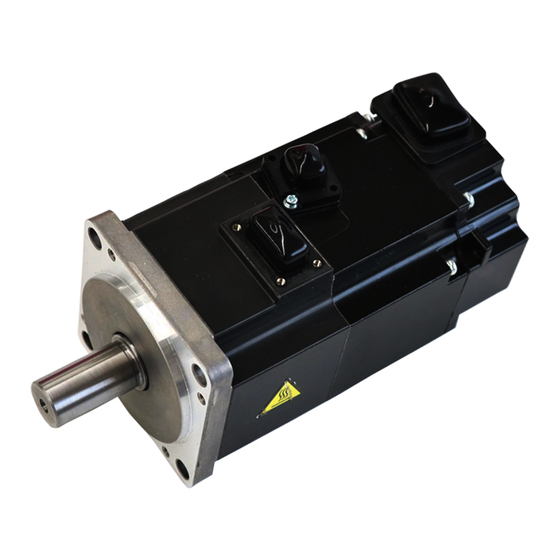
1. INTRODUCTION 1.2 Parts identification (1) HG-MR series/HG-KR series servo motor Power cable (Note 1, 2) Encoder cable (Note 1) Power lead (U/V/W) Grounding lead Servo motor shaft Encoder Note 1. The encoder cable and power supply cable are options. -
Page 17: Electromagnetic Brake
1. INTRODUCTION 1.3 Electromagnetic brake The electromagnetic brake is provided to prevent a drop at a power failure or alarm occurrence during vertical drive or to hold a shaft at a stop. Do not use it for normal braking (including braking at servo-lock). The electromagnetic brake has a time lag. - Page 18 1. INTRODUCTION (2) Sound generation Though the brake lining may rattle during operation, it poses no functional problem. If braking sounds, it may be improved by setting the machine resonance suppression filter in the servo amplifier (converter unit) parameters. For details, refer to each servo amplifier instruction manual. (3) Selection of surge absorbers for electromagnetic brake circuit The following shows an example how to select a varistor with a surge absorber.
-
Page 19: Servo Motor Shaft Shapes
1. INTRODUCTION (4) Others A leakage magnetic flux will occur at the shaft end of the servo motor equipped with an electromagnetic brake. Note that chips, screws, etc. are attracted. 1.4 Servo motor shaft shapes In addition to the straight shaft, the key shaft and D cut shaft are available. The key shaft and D cut shaft cannot be used in frequent start/stop applications. -
Page 20: Servo Motor With Functional Safety
1. INTRODUCTION 1.5 Servo motor with functional safety POINT When you use a servo motor with functional safety, MR-BT6VCASE battery case cannot be used. The servo motors with functional safety can expand the safety observation function by using them with MR- D30 functional safety units and MR-J4-_-RJ servo amplifiers. - Page 21 1. INTRODUCTION (2) HG-SR series Servo motors with functional safety Servo amplifier HG-SR51W0C MR-J4-60B-RJ HG-SR52W0C MR-J4-60A-RJ MR-J4-60GF-RJ HG-SR81W0C MR-J4-100B-RJ HG-SR102W0C MR-J4-100A-RJ MR-J4-100GF-RJ HG-SR121W0C MR-J4-200B-RJ HG-SR201W0C MR-J4-200A-RJ HG-SR152W0C MR-J4-200GF-RJ HG-SR202W0C HG-SR301W0C MR-J4-350B-RJ HG-SR352W0C MR-J4-350A-RJ MR-J4-350GF-RJ HG-SR421W0C MR-J4-500B-RJ HG-SR502W0C MR-J4-500A-RJ MR-J4-500GF-RJ HG-SR702W0C MR-J4-700B-RJ MR-J4-700A-RJ MR-J4-700GF-RJ...
- Page 22 1. INTRODUCTION (3) HG-JR series Servo motors with functional safety Servo amplifier HG-JR53W0C MR-J4-60B-RJ MR-J4-60A-RJ MR-J4-60GF-RJ MR-J4-100B-RJ (Note 1) MR-J4-100A-RJ (Note 1) MR-J4-100GF-RJ (Note 1) HG-JR73W0C MR-J4-70B-RJ MR-J4-70A-RJ MR-J4-70GF-RJ MR-J4-200B-RJ (Note 1) MR-J4-200A-RJ (Note 1) MR-J4-200GF-RJ (Note 1) HG-JR103W0C MR-J4-100B-RJ MR-J4-100A-RJ MR-J4-100GF-RJ MR-J4-200B-RJ (Note 1)
- Page 23 1. INTRODUCTION Servo motors with functional safety Servo amplifier HG-JR534W0C MR-J4-60B4-RJ MR-J4-60A4-RJ MR-J4-60GF4-RJ MR-J4-100B4-RJ (Note 1) MR-J4-100A4-RJ (Note 1) MR-J4-100GF4-RJ (Note 1) HG-JR734W0C MR-J4-100B4-RJ HG-JR1034W0C MR-J4-100A4-RJ MR-J4-100GF4-RJ MR-J4-200B4-RJ (Note 1) MR-J4-200A4-RJ (Note 1) MR-J4-200GF4-RJ (Note 1) HG-JR1534W0C MR-J4-200B4-RJ HG-JR2034W0C MR-J4-200A4-RJ MR-J4-200GF4-RJ MR-J4-350B4-RJ (Note 1) MR-J4-350A4-RJ (Note 1)
- Page 24 2. INSTALLATION 2. INSTALLATION WARNING To prevent electric shock, ground each equipment securely. Stacking in excess of the specified number of product packages is not allowed. Install the servo motor on incombustible material. Installing them directly or close to combustibles will lead to smoke or a fire. Install the servo motor in a load-bearing place in accordance with the Instruction Manual.
-
Page 25: Mounting Direction
2. INSTALLATION 2.1 Mounting direction (1) Standard servo motor The following table indicates the mounting direction of the standard servo motor. Servo motor series Mounting direction HG-MR HG-KR HG-SR HG-JR All directions HG-RR HG-UR HG-AK For mounting in the horizontal direction, it is recommended to set the connector section downward. -
Page 26: Load Remove Precautions
2. INSTALLATION 2.3 Load remove precautions During assembling, the shaft end must not be hammered. Otherwise, the encoder may malfunction. CAUTION Do not process the shaft to avoid damage to the encoder and bearing. (1) When mounting a pulley to the servo motor with a key shaft, use the screw hole in the shaft end. To fit the pulley, first insert a double-end stud into the screw hole of the shaft, put a washer against the end face of the coupling, and insert and tighten a nut to force the pulley in. -
Page 27: Permissible Load For The Shaft
2. INSTALLATION 2.4 Permissible load for the shaft Do not use a rigid coupling as it may apply excessive bending load to the shaft of CAUTION the servo motor, leading the shaft to break and the bearing to wear out. For the permissible shaft load specific to the servo motor, refer to the chapter of the servo motor series. -
Page 28: Cable
2. INSTALLATION 2.6 Cable The power supply and encoder cables routed from the servo motor should be fixed to the servo motor to keep them unmovable. Otherwise, the cable may disconnect. In addition, do not modify the connectors, terminals and others at the ends of the cables. 2.7 Servo motor with oil seal For the servo motor with oil seal, the oil seal prevents the entry of oil into the servo motor. -
Page 29: Parts Having Service Life
2. INSTALLATION It is recommended that the following points periodically be checked. (1) Check the bearings, brake section, etc. for unusual noise. (2) Check the cables and the like for scratches or cracks. Especially when the cable is movable, perform periodic inspection according to operating conditions. -
Page 30: Machine Accuracies
2. INSTALLATION 2.11 Machine accuracies The following table indicates the machine accuracies of the servo motor around the output shaft and mounting. (except the optional products) Flange size Measuring Accuracy [mm] 100 × 100 or 176 × 176 to position 130 ×... -
Page 31: Mounting Servo Motors
The temperature of the servo motor increases differently depending on its mounting environment, operating conditions, etc. Make sure to check the temperature with an actual machine. Servo motor Flange size [mm] HG-MR/HG-KR HG-SR HG-JR HG-RR HG-UR HG-AK 0136 150 ×... -
Page 32: Selection Of Connectors
Use the connector configuration products given in the table as the connectors for connection with the servo motor. Refer to section 3.2 to 3.4 for the compatible connector configuration products. (1) HG-MR series and HG-KR series Encoder connector Electromagnetic brake connector... - Page 33 3. CONNECTORS USED FOR SERVO MOTOR WIRING (3) HG-JR series HG-JR53(4) to HG-JR903(4)/HG-JR701M(4) to HG-JR15K1M(4)/HG-JR601(4) to HG-JR12K1(4) Electromagnetic brake connector Encoder connector Power supply connector HG-JR22K1M(4) to HG-JR37K1M(4)/HG-JR45K1M4/HG-JR55K1M4/HG-JR15K1(4) to HG-JR37K1(4) Cooling fan connector Encoder connector Wiring connector Servo motor For electromagnetic For encoder For power supply For cooling fan...
- Page 34 3. CONNECTORS USED FOR SERVO MOTOR WIRING (4) HG-RR series Encoder connector Power connector Wiring connector Servo motor For electromagnetic For encoder For power supply brake HG-RR103 Connector HG-RR153 configuration N Connector Sharing for power HG-RR203 configuration D supply HG-RR353 Connector configuration M HG-RR503...
- Page 35 3. CONNECTORS USED FOR SERVO MOTOR WIRING (6) HG-AK series Power connector Encoder connector Wiring connector Servo motor For electromagnetic For encoder For power supply brake HG-AK0136 Connector configuration Connector configuration Sharing for power supply HG-AK0236 (Note) HG-AK0336 Note. An electromagnetic brake connector is not required since the power connector has a pin assigned for electromagnetic brake.
-
Page 36: Wiring Connectors (Connector Configurations A/B/C)
3. CONNECTORS USED FOR SERVO MOTOR WIRING 3.2 Wiring connectors (connector configurations A/B/C) Connector Servo motor encoder Connector Crimping tool Feature configuration connector (Note) For ground clip: 1596970-1 Connector: 2174053-1 1674339-1 For REC. contact: 1596847-1 IP65 (for encoder) (TE Connectivity) (TE Connectivity) (TE Connectivity) Note. -
Page 37: Wiring Connectors (Connector Configurations D/E/F/G/H)
3. CONNECTORS USED FOR SERVO MOTOR WIRING 3.3 Wiring connectors (connector configurations D/E/F/G/H) Angle plug Angle plug (one-touch connection type) (screw type) Straight plug Straight plug (one-touch connection type) (screw type) Plug (DDK) Servo motor Connector Cable OD encoder Feature configuration Type Plug... - Page 38 3. CONNECTORS USED FOR SERVO MOTOR WIRING Plug Cable clamp Cable Plug Cable clamp Cable Plug (DDK) Cable clamp (DDK) Servo motor Connector power supply Feature Cable OD connector configuration Type Model Model [mm] (reference) (Note 2) 8.5 to 11 CE3057-10A-2-D CE05-6A18-10SD-D-BSS Straight...
- Page 39 3. CONNECTORS USED FOR SERVO MOTOR WIRING Angle plug Angle plug (one-touch connection type) (screw type) Straight plug Straight plug (one-touch connection type) (screw type) Plug (DDK) Servo motor electro- Connector Cable OD Feature magnetic brake configuration Type Plug Socket contact Contact shape [mm] connector...
- Page 40 3. CONNECTORS USED FOR SERVO MOTOR WIRING Plug Cable clamp Cable Plug Cable clamp Cable Plug (DDK) Cable clamp (DDK) Servo motor Connector power supply Feature Cable OD connector configuration Type Model Model [mm] (reference) (Note 2) 9.5 to 13 CE3057-12A-2-D CE05-6A22-22SD-D-BSS Straight...
-
Page 41: Wiring Connectors (Connector Configurations J/K/L/M/N/P/Q)
3. CONNECTORS USED FOR SERVO MOTOR WIRING 3.4 Wiring connectors (connector configurations J/K/L/M/N/P/Q) Cable Plug Cable Connector for cable Cable Plug clamp Cable Plug Connector for cable IP67 compatible IP67 compatible General environmental Cable-side connector Servo motor Connector for cable electromagnetic Connector brake... - Page 42 3. CONNECTORS USED FOR SERVO MOTOR WIRING Cable clamp Plug Plug (DDK) Cable clamp Servo motor Connector Feature cooling fan Cable OD configuration Type Model Model connector (Note) [mm] (reference) IP67 CE05-6A14S-2SD-D (for YSO14-9 to 11 Straight 8.3 to 11.3 CE05-2A14S-2P cooling Applicable wire size: AWG 22 to 16...
- Page 43 3. CONNECTORS USED FOR SERVO MOTOR WIRING Plug Cable clamp Cable Plug Cable clamp Cable Plug (DDK) Cable clamp (DDK) Servo motor Connector Feature power supply Cable OD configuration Type Model Model connector (Note) [mm] (reference) 9.5 to 13 CE3057-12A-2-D CE05-6A22-23SD-D-BSS IP65 Straight...
- Page 44 4. CONNECTION OF SERVO AMPLIFIER AND SERVO MOTOR 4. CONNECTION OF SERVO AMPLIFIER AND SERVO MOTOR Any person who is involved in wiring should be fully competent to do the work. Ground the servo motor securely. Do not attempt to wire the servo motor until it has been mounted. Otherwise, it may cause an electric shock.
-
Page 45: Connection Instructions
4. CONNECTION OF SERVO AMPLIFIER AND SERVO MOTOR 4.1 Connection instructions To avoid a malfunction, connect the wires to the correct phase terminals (U/V/W) of the servo amplifier (converter unit) and servo motor. Do not connect AC power supply directly to the servo motor. Otherwise, it may CAUTION cause a malfunction. -
Page 46: Wiring
4. CONNECTION OF SERVO AMPLIFIER AND SERVO MOTOR 4.2 Wiring 4.2.1 HG-MR series/HG-KR series servo motor (1) Connection with MR-J4 1-axis servo amplifier (a) Servo motor power supply cable wiring diagrams 1) When cable length is 10 m or less... - Page 47 4. CONNECTION OF SERVO AMPLIFIER AND SERVO MOTOR (b) Electromagnetic brake cable wiring diagrams 1) When cable length is 10 m or less 10 m or less MR-BKS1CBL_M-A1-L MR-BKS1CBL_M-A2-L MR-BKS1CBL_M-A1-H (Note 3) Servo motor MR-BKS1CBL_M-A2-H 24 V DC power supply (Electromagnetic (Note 2) for electromagnetic...
- Page 48 4. CONNECTION OF SERVO AMPLIFIER AND SERVO MOTOR (2) Connection with MR-J4 multi-axis servo amplifier (a) Servo motor power supply cable wiring diagrams 1) When cable length is 10 m or less 10 m or less MR-PWS1CBL_M-A1-L MR-PWS1CBL_M-A2-L MR-PWS1CBL_M-A1-H Servo amplifier Servo motor MR-PWS1CBL_M-A2-H CNP3A/CNP3B/...
- Page 49 4. CONNECTION OF SERVO AMPLIFIER AND SERVO MOTOR (b) Electromagnetic brake cable wiring diagrams 1) When cable length is 10 m or less 10 m or less MR-BKS1CBL_M-A1-L MR-BKS1CBL_M-A2-L MBR-A MR-BKS1CBL_M-A1-H (Note 4) Servo motor CALM (Electromagnetic MR-BKS1CBL_M-A2-H 24 V DC power supply (Note 2) (AND brake interlock...
- Page 50 4. CONNECTION OF SERVO AMPLIFIER AND SERVO MOTOR 2) When cable length exceeds 10 m Fabricate an extension cable as shown below. In addition, the electromagnetic brake cable should be within 2 m. Refer to section 4.3 for the wire used for the extension cable. 50 m or less 2 m or less MR-BKS1CBL2M-A1-L...
-
Page 51: Hg-Sr Series/Hg-Jr Series/Hg-Rr Series/Hg-Ur Series Servo Motor
4. CONNECTION OF SERVO AMPLIFIER AND SERVO MOTOR 4.2.2 HG-SR series/HG-JR series/HG-RR series/HG-UR series servo motor Refer to section 4.3 for the wires used for wiring. (1) Wiring diagrams (a) Connection with MR-J4 1-axis servo amplifier (Note 4) Power supply cooling fan 50 m or less Servo amplifier... - Page 52 4. CONNECTION OF SERVO AMPLIFIER AND SERVO MOTOR (b) Connection with MR-J4 multi-axis servo amplifier 50 m or less Servo amplifier A-axis servo motor CNP3A (Note 2) MBR-A CALM 24 V DC power supply (Electromagnetic (AND for electromagnetic brake interlock malfunction) brake for A-axis)
- Page 53 4. CONNECTION OF SERVO AMPLIFIER AND SERVO MOTOR (2) Servo motor terminal section The following table shows the servo motor terminal section. For details of the connectors, refer to (3) in this section. For details of the terminal box, refer to (4) in this section. The connector fitting the servo motor is prepared as options.
- Page 54 4. CONNECTION OF SERVO AMPLIFIER AND SERVO MOTOR (c) HG-RR series Servo motor terminal section Servo motor Electromagnetic Encoder Power brake HG-RR103 HG-RR153 Connector F The connector for HG-RR203 Connector A power is shared HG-RR353 Connector G HG-RR503 (d) HG-UR series Servo motor terminal section Servo motor Electromagnetic...
- Page 55 4. CONNECTION OF SERVO AMPLIFIER AND SERVO MOTOR Connector D Connector E Connector F Power supply connector Power supply connector Power supply connector MS3102A22-22P MS3102A32-17P CE05-2A22-23P Terminal Terminal Terminal Signal Signal Signal (PE) (PE) (PE) (Note) (Note) Note. For the motor with an electromagnetic brake, supply...
- Page 56 4. CONNECTION OF SERVO AMPLIFIER AND SERVO MOTOR Connector K Connector L Cooling fan connector Encoder connector CE05-2A14S-2P MS3102A20-29P Terminal Signal Signal (Note) (Note) (Note) Note. Refer to the chapter of the THM1 servo motor THM2 series for the specifications of the power supplied to the cooling fan.
-
Page 57: Hg-Ak Series Servo Motor
4. CONNECTION OF SERVO AMPLIFIER AND SERVO MOTOR 4.2.3 HG-AK series servo motor (1) Connection with MR-J4-03A6(-RJ) servo amplifier (a) Motor power cable wiring diagram (without electromagnetic brake) 30 m or less 0.2 m Servo amplifier Servo motor MR-J4W03PWCBL_M-H Power cable supplied CNP1 with the servo motor (b) Motor power cable wiring diagram (with electromagnetic brake) - Page 58 4. CONNECTION OF SERVO AMPLIFIER AND SERVO MOTOR (2) Connection with MR-J4W2-0303B6 servo amplifier (a) Motor power cable wiring diagram (without electromagnetic brake) 30 m or less 0.2 m Servo amplifier A-axis servo motor MR-J4W03PWCBL_M-H Power cable supplied B-axis servo motor CNP1 with the servo motor MR-J4W03PWCBL_M-H...
-
Page 59: Selection Example Of Wires
4. CONNECTION OF SERVO AMPLIFIER AND SERVO MOTOR 4.3 Selection example of wires POINT Wires indicated in this section are separated wires. When using a cable for power line (U/V/W) between the servo amplifier and servo motor, use a 600 V grade EP rubber insulated chloroprene sheath cab-tire cable (2PNCT). - Page 60 4. CONNECTION OF SERVO AMPLIFIER AND SERVO MOTOR The following shows examples for using the 600 V Grade heat-resistant polyvinyl chloride insulated wire (HIV wire). (1) HG-MR series and HG-KR series Wire [mm Servo motor 1) U/V/W/ 2) B1/B2 HG-MR053...
- Page 61 4. CONNECTION OF SERVO AMPLIFIER AND SERVO MOTOR (3) HG-JR series (a) 3000 r/min series Wire [mm 1) U/V/W/ Servo motor When the 2) B1/B2 Standard maximum torque is 400% (Note 2) HG-JR53 HG-JR73 1.25 (AWG 16) 1.25 (AWG 16) HG-JR103 HG-JR153 2 (AWG 14)
- Page 62 4. CONNECTION OF SERVO AMPLIFIER AND SERVO MOTOR (b) 1500 r/min series Wire [mm Servo motor 1) U/V/W/ 2) B1/B2 3) BU/BV/BW 8 (AWG 8) HG-JR701M (Note 1, 2) HG-JR11K1M 14 (AWG 6) (Note 1) 1.25 (AWG 16) HG-JR15K1M 22 (AWG 4) (Note 1) HG-JR22K1M 38 (AWG 2) (Note 1) HG-JR30K1M...
- Page 63 4. CONNECTION OF SERVO AMPLIFIER AND SERVO MOTOR (4) HG-RR series Wire [mm Servo motor 1) U/V/W/ 2) B1/B2 HG-RR103 2 (AWG 14) HG-RR153 HG-RR203 3.5 (AWG 12) 1.25 (AWG 16) HG-RR353 5.5 (AWG 10) (Note) HG-RR503 Note. Refer to each servo amplifier instruction manual for crimp terminals and crimping tools used for connection with the servo amplifier.
-
Page 64: Servo Amplifier Terminal Section
4. CONNECTION OF SERVO AMPLIFIER AND SERVO MOTOR 4.4 Servo amplifier terminal section POINT For the sizes of wires used for wiring, refer to section 4.3. When wiring, remove the power connectors from the servo amplifier. Insert only one wire or ferrule to each wire insertion hole. The drive unit do not have these connectors. - Page 65 4. CONNECTION OF SERVO AMPLIFIER AND SERVO MOTOR (1) Connector details (a) Connector A Servo amplifier CNP3 Table 4.1 Connector and applicable wire Applicable wire Stripped Connector Receptacle assembly Open tool Manufacturer length [mm] Wire size Insulator OD J-FAT-OT (N) CNP3 03JFAT-SAXGDK-H7.5 AWG 18 to 14...
- Page 66 4. CONNECTION OF SERVO AMPLIFIER AND SERVO MOTOR (c) Connector C MR-J4W_ Servo amplifier CNP3A CNP3B CNP3C (Note) Note. This figure shows the MR-J4 3-axis servo amplifier. Table 4.3 Connector and applicable wire Stripped Connector Receptacle assembly Applicable wire size Open tool Manufacturer length [mm]...
- Page 67 4. CONNECTION OF SERVO AMPLIFIER AND SERVO MOTOR (e) Connector E MR-J4-03A6(-RJ) servo amplifier CNP1 Table 4.5 Connector and applicable wire Stripped Connector Receptacle assembly Applicable wire size Manufacturer length [mm] DFMC 1,5/ 4-ST-3,5-LR CNP1 AWG 24 to 16 Phoenix Contact or equivalent (f) Connector F MR-J4W2-0303B6...
- Page 68 4. CONNECTION OF SERVO AMPLIFIER AND SERVO MOTOR (2) Cable connection procedure (a) Cable making Refer to table 4.1 to 4.4 for stripped length of cable insulator. The appropriate stripped length of cables depends on their type, etc. Set the length considering their status. Insulator Core Stripped length...
- Page 69 4. CONNECTION OF SERVO AMPLIFIER AND SERVO MOTOR 2) For connectors not requiring an open tool (connector E and connector F) When using solid wire, insert the wire to the end. When using stranded wire, insert the wire to the end while pushing the release button with a small flat head screwdriver, etc.
-
Page 70: Cable/Connector Sets
5. WIRING OPTION 5. WIRING OPTION Before connecting any option, turn off the power and wait for 15 minutes or more (20 minutes or more for converter unit and drive unit) until the charge lamp turns off. Then, confirm that the voltage between P+ and N- (L+ and L- for converter WARNING unit and drive unit) is safe with a voltage tester and others. -
Page 71: Combinations Of Cable/Connector Sets
5. WIRING OPTION 5.1.1 Combinations of cable/connector sets (1) HG-MR series/HG-KR series servo motor MR-J4 1-axis Direct connection (cable length 10 m or less, IP65) servo amplifier 13) 14) 15) 16) CNP3 Junction connection (cable length more than 10 m, IP65) - Page 72 5. WIRING OPTION (3) HG-JR22K1M(4) to HG-JR37K1M(4)/HG-JR45K1M4/HG-JR55K1M4/HG-JR15K1(4) to HG-JR37K1(4) servo motor Servo amplifier 40) (Note) Terminal box MR-BAT6V1BJ Cooling fan Encoder connector connector Note. MR-ENECBL_M-H cannot be used. (4) HG-AK series servo motor MR-J4-03A6(-RJ) servo amplifier CNP1 45) 46) MR-J4W2-0303B6 servo amplifier CN2A 49) 50)
-
Page 73: Cable And Connector List
Description Remark Servo motor IP65 Power supply connector power cable PWS1CBL_M- Load-side A1-L (Note 1, 2) lead HG-MR series Cable length: HG-KR series 2/5/10 m Refer to section 5.3 for details. Servo motor IP65 power cable PWS1CBL_M- Load-side A1-H (Note 1) - Page 74 Model Description Remark Electromagnetic IP55 Electromagnetic brake connector brake cable BKS2CBL03M- Opposite A2-L to load- HG-MR series Cable length: side lead HG-KR series 0.3 m Refer to section 5.5 for details. Encoder cable IP65 Encoder connector J3ENCBL_M- Load-side A1-L (Note 1)
- Page 75 Name Model Description Remark Encoder cable IP65 Encoder connector J3JSCBL03M- Load-side A2-L (Note 1) lead HG-MR series Cable length: HG-KR series 0.3 m Refer to section 5.2 (4) for details. Encoder cable IP67 J3ENSCBL_M- Standard L (Note 1) HG-KR/HG-MR/HG-SR/HG-RR/HG-UR series/...
- Page 76 Angle plug: CMV1S-AP2S-L IP67 brake connector Socket contact: CMV1-#22BSC-S2-100 (DDK) HG-SR series HG-JR53(4) HG-JR73(4) HG-JR103(4) HG-JR153(4) HG-JR203(4) HG-JR353(4) HG-JR503(4) HG-JR703(4) HG-JR903(4) Encoder MR-ENCNS2 IP67 Connector set HG-KR/HG-MR/HG-SR/HG-RR/HG-UR series/ HG-JR53(4)/HG-JR73(4)/HG-JR103(4)/HG-JR153(4)/HG-JR203(4)/ HG-JR353(4)/HG-JR503(4)/HG-JR703(4)/HG-JR903(4) Refer to section 5.2 (5) for details. 5 - 7...
- Page 77 5. WIRING OPTION Name Model Description Remark Encoder MR-J3SCNSA IP67 (Note 1) Connector set HG-KR/HG-MR/HG-SR/HG-RR/HG-UR series/ HG-JR53(4)/HG-JR73(4)/HG-JR103(4)/HG-JR153(4)/HG-JR203(4)/ HG-JR353(4)/HG-JR503(4)/HG-JR703(4)/HG-JR903(4) Refer to section 5.2 (5) for details. Encoder MR-ENCNS2A IP67 Connector set HG-KR/HG-MR/HG-SR/HG-RR/HG-UR series/ HG-JR53(4)/HG-JR73(4)/HG-JR103(4)/HG-JR153(4)/HG-JR203(4)/ HG-JR353(4)/HG-JR503(4)/HG-JR703(4)/HG-JR903(4) Refer to section 5.2 (5) for details.
- Page 78 5. WIRING OPTION Name Model Description Remark Cooling fan power MR-PWCNF Plug: CE05-6A14S-2SD-D (DDK) IP67 connector set Cable clamp: YSO14-9 to 11 (Daiwa Dengyo) HG-JR22K1M(4) compliant Applicable cable HG-JR30K1M(4) Applicable wire size: 0.3 mm to 1.25 mm (AWG 22 to 16) HG-JR37K1M(4) HG-JR45K1M4 Cable OD: 8.3 mm to 11.3 mm...
-
Page 79: Encoder Cable/Connector Sets
5. WIRING OPTION 5.2 Encoder cable/connector sets POINT For CN2, CN2A, CN2B, and CN2C side connectors, securely connect the shielded external conductor of the cable to the ground plate and fix it to the connector shell. Cable Ground plate Screw Encoder cables are not subject to European Low Voltage Directive (50 V AC to 1000 V AC and 75 V DC to 1500 V DC). - Page 80 5. WIRING OPTION (1) MR-J3ENCBL_M-_-_ These cables are encoder cables for the HG-MR/HG-KR series servo motors. The numbers in the cable length field of the table indicate the symbol filling the underline "_" in the cable model. Cable length Cable model...
- Page 81 Cable length Cable model IP rating Bending life Application 20 m 30 m 40 m 50 m (Note) MR-EKCBL_M-L IP20 Standard For HG-MR/HG-KR Use in combination with MR- (Note) (Note) (Note) Long J3JCBL03M-_-L. MR-EKCBL_M-H IP20 bending life Note. Four-wire type cable...
- Page 82 (a) Connection of servo amplifier and servo motor MR-J4 1-axis servo amplifier MR-EKCBL_M-L MR-J3JCBL03M-A2-L MR-EKCBL_M-H Cable length: 0.3 m Servo motor MR-J4 multi-axis HG-MR servo amplifier HG-KR CN2A CN2B (Note) CN2C Note. This connection is for the MR-J4 3-axis servo amplifier. Cable model...
- Page 83 5. WIRING OPTION (b) Internal wiring diagram MR-EKCBL30M-L MR-EKCBL20M-L CN2, CN2A, CN2B, and Junction CN2, CN2A, CN2B, and Junction CN2C side connector connector CN2C side connector connector Plate (Note) CONT Plate (Note) MR-EKCBL30M-H MR-EKCBL40M-H MR-EKCBL20M-H MR-EKCBL50M-H CN2, CN2A, CN2B, and Junction CN2, CN2A, CN2B, and Junction...
- Page 84 The servo amplifier and the servo motor cannot be connected by these cables alone. The servo motor- side encoder cable (MR-EKCBL_M-_) is required. Cable model Cable length IP rating Bending life Application Load-side lead for HG-MR/HG-KR MR-J3JCBL03M-A1-L Use in combination with MR- EKCBL_M-_. 0.3 m IP20 Standard...
- Page 85 5. WIRING OPTION (a) Connection of servo amplifier and servo motor MR-J4 1-axis servo amplifier MR-J3JCBL03M-A1-L Servo motor HG-MR HG-KR MR-EKCBL_M-_ MR-J4 multi-axis servo amplifier CN2A MR-J3JCBL03M-A2-L CN2B Servo motor (Note) CN2C HG-MR HG-KR Note. This connection is for the MR-J4 3-axis servo amplifier.
- Page 86 The servo amplifier and the servo motor cannot be connected by these cables alone. The servo motor- side encoder cable (MR-J3ENSCBL_M-_) is required. Cable model Cable length IP rating Bending life Application For HG-KR/HG-MR Load-side lead MR-J3JSCBL03M-A1-L Use in combination with MR- J3ENSCBL_M-_. 0.3 m IP65...
- Page 87 (5) MR-J3ENSCBL_M-_ These cables are encoder cables for the HG-MR/HG-KR/HG-SR/HG-RR/HG-UR series/HG- JR53(4)/HGJR73(4)/HG-JR103(4)/HG-JR153(4)/HG-JR203(4)/HG-JR353(4)/HG-JR503(4)/HG- JR703(4) and HG-JR903(4) servo motors. The numbers in the cable length field of the table indicate the symbol filling the underline "_" in the cable model.
- Page 88 5. WIRING OPTION 1) CN2, CN2A, CN2B, and CN2C Cable model 2) Encoder-side connector side connector MR-J3ENSCBL_M- Receptacle: 36210-0100PL Plug (DDK) Cable Shell kit: 36310-3200-008 Bending life length Straight plug Socket contact (3M) Long CMV1-#22ASC-C1-100 bending life 10 m or Applicable wire size: AWG 24 shorter to 20...
- Page 89 5. WIRING OPTION (b) Cable internal wiring diagram MR-J3ENSCBL2M-L MR-J3ENSCBL5M-L MR-J3ENSCBL10M-L MR-J3ENSCBL2M-H MR-J3ENSCBL5M-H MR-J3ENSCBL20M-L MR-J3ENSCBL10M-H MR-J3ENSCBL30M-L CN2, CN2A, CN2B, and Encoder-side CN2, CN2A, CN2B, and Encoder-side CN2C side connector connector CN2C side connector connector Plate (Note) Plate (Note) MR-J3ENSCBL20M-H MR-J3ENSCBL30M-H MR-J3ENSCBL40M-H MR-J3ENSCBL50M-H CN2, CN2A, CN2B, and...
- Page 90 5. WIRING OPTION (c) When fabricating the encoder cable Prepare the following parts, and fabricate it according to the wiring diagram in (b) in this section. Refer to section 5.5 for the specifications of the used cable. Description Parts (Connector set) Servo amplifier side connector Encoder-side connector (DDK) MR-J3SCNS...
- Page 91 5. WIRING OPTION (6) MR-ENECBL_M-H-MTH These cables are encoder cables for HG-JR701M(4), HG-JR11K1M(4), HG-JR15K1M(4), HG- JR22K1M(4), HG-JR30K1M(4), HG-JR37K1M(4), HG-JR45K1M4, HG-JR55K1M4, HG-JR601(4), HG- JR801(4), HG-JR12K1(4), HG-JR15K1(4), HG-JR20K1(4), HG-JR25K1(4), HG-JR30K1(4), and HG- JR37K1(4) servo motors. The numbers in the cable length field of the table indicate the symbol filling the underline "_"...
- Page 92 5. WIRING OPTION (b) Cable internal wiring diagram MR-ENECBL2M-H-MTH MR-ENECBL5M-H-MTH MR-ENECBL10M-H-MTH MR-ENECBL20M-H-MTH CN2-side Encoder-side CN2-side Encoder-side connector connector connector connector THM1 THM1 THM1 THM1 THM2 THM2 THM2 THM2 Plate Plate (Note 2) (Note 2) (Note 1) (Note 1) MR-ENECBL30M-H-MTH MR-ENECBL40M-H-MTH MR-ENECBL50M-H-MTH Encoder-side CN2-side...
- Page 93 Additionally, you can change the battery with the control circuit power supply off. For details, refer to each servo amplifier instruction manual. Cable model Cable length Application For HG-MR/HG-KR/HG-SR/HG-JR/HG- MR-BT6VCBL03M 0.3 m RR/HG-UR series Connection of servo amplifier and servo motor...
- Page 94 5. WIRING OPTION (8) MR-J3W03ENCBL_M-A-H These cables are encoder cables for the HG-AK series servo motors. The numbers in the cable length field of the table indicate the symbol filling the underline "_" in the cable model. Cable length Cable model IP rating Bending life Application...
- Page 95 5. WIRING OPTION Cable model 1) CN2, CN2A, and CN2B-side connector 2) Encoder-side connector MR-J3W03ENCBL_ Receptacle housing: 1-1827862-5 Tab housing: J21DPM-10V-KX M-A-H Contact: 1827587-2 Contact: SJ2M-01GF-M1.0N Crimping tool: 1762846-1 Crimping tool: YRS-8861 (TE Connectivity) (JST) Note. Do not connect anything to the pins shown as Note.
-
Page 96: Servo Motor Power Cable
5. WIRING OPTION 5.3 Servo motor power cable These cables are servo motor power cables for the HG-MR/HG-KR series servo motors. The numbers in the cable length field of the table indicate the symbol filling the underline "_" in the cable model. - Page 97 5. WIRING OPTION (2) Internal wiring diagram (Red) (White) (Note) (Black) (Green/yellow) Note. These are not shielded cables. 5 - 28...
-
Page 98: Servo Motor Power Cable (For Hg-Ak Series)
5. WIRING OPTION 5.4 Servo motor power cable (for HG-AK series) These cables are servo motor power cables for the HG-AK series servo motors. The numbers in the cable length field of the table indicate the symbol filling the underline "_" in the cable model. Refer to section 4.2.3 for wiring. -
Page 99: Electromagnetic Brake Cable
(JST) 5.5 Electromagnetic brake cable These cables are electromagnetic brake cables for the HG-MR/HG-KR series servo motors. The numbers in the cable length field of the table indicate the symbol filling the underline "_" in the cable model. Refer to section 4.2.1 for wiring. - Page 100 5. WIRING OPTION (1) Connection of power supply for electromagnetic brake and servo motor MR-BKS1CBL_M-A1-L MR-BKS1CBL_M-A1-H MR-BKS2CBL03M-A1-L Servo motor 24 V DC power HG-MR supply for HG-KR electromagnetic brake MR-BKS1CBL_M-A2-L MR-BKS1CBL_M-A2-H MR-BKS2CBL03M-A2-L Servo motor HG-MR HG-KR Cable model 1) Connector for electromagnetic brake...
-
Page 101: Wires For Option Cables
5. WIRING OPTION 5.6 Wires for option cables When fabricating a cable, use the wire models given in the following table or equivalent. Table 5.1 Wires for option cables Characteristics of one core (Note 2) (Note 1) Length Wire model Core Structure Number... - Page 102 5. WIRING OPTION Characteristics of one core (Note 2) (Note 1) Length Wire model Core Structure Number Conductor Type Model Cable OD Insulator size of cores (Manufacturer) [Number of resistance [mm] [Ω/km] wires/mm] d [mm] (Note 3) TPE•SVP 70/0.08(AWG#22 or 1 to 10 AWG 22 70/0.08 1.17...
- Page 103 5. WIRING OPTION MEMO 5 - 34...
-
Page 104: Model Code Definition
6. HG-MR SERIES/HG-KR SERIES 6. HG-MR SERIES/HG-KR SERIES This chapter provides information on the servo motor specifications and characteristics. When using the HG- MR/HG-KR series servo motor, always read the Safety Instructions in the beginning of this manual and chapters 1 to 5, in addition to this chapter. -
Page 105: Combination List Of Servo Motors And Servo Amplifiers
6. HG-MR SERIES/HG-KR SERIES 6.2 Combination list of servo motors and servo amplifiers Servo amplifier Servo motor MR-J4 1-axis MR-J4 2-axis MR-J4 3-axis 200 V class 100 V class MR-J4-10A MR-J4-10A-RJ HG-MR053 MR-J4-10A1 MR-J4-10B MR-J4-10A1-RJ MR-J4-10B-RJ MR-J4-10B1 MR-J4-10B-RJ010 MR-J4-10B1-RJ MR-J4-10B-RJ020... - Page 106 6. HG-MR SERIES/HG-KR SERIES Servo amplifier MR-J4 1-axis Servo motor MR-J4 2-axis MR-J4 3-axis 200 V class 100 V class MR-J4-70A MR-J4-70A-RJ MR-J4-70B MR-J4-70B-RJ MR-J4W2-77B HG-KR73 MR-J4-70B-RJ010 MR-J4W2-1010B MR-J4-70B-RJ020 MR-J4-70GF MR-J4-70GF-RJ 6 - 3...
-
Page 107: Standard Specifications
6. HG-MR SERIES/HG-KR SERIES 6.3 Standard specifications 6.3.1 Standard specifications list HG-MR series Servo motor HG-KR series (low inertia/small capacity) (ultra-low inertia/small capacity) Item 053(B) 13(B) 23(B) 43(B) 73(B) 053(B) 13(B) 23(B) 43(B) 73(B) Refer to "Power supply equipment capacity and generated loss of servo amplifiers" in Power supply capacity Servo Amplifier Instruction Manual. - Page 108 6. HG-MR SERIES/HG-KR SERIES Note 1. When the power supply voltage drops, the output and the rated speed cannot be guaranteed. 2. If the load to motor inertia ratio exceeds the indicated value, contact your local sales office. 3. Refer to the dimensions for the geared servo motor.
-
Page 109: Torque Characteristics
6. HG-MR SERIES/HG-KR SERIES 6.3.2 Torque characteristics POINT For the system where the unbalanced torque occurs, such as a vertical axis system, the unbalanced torque of the machine should be kept at 70% or less of the rated torque. When the power supply input of the servo amplifier is 3-phase 200 V AC or 1-phase 230 V AC, the torque characteristic is indicated by the heavy line. -
Page 110: Electromagnetic Brake Characteristics
6. HG-MR SERIES/HG-KR SERIES 6.4 Electromagnetic brake characteristics The electromagnetic brake is provided to prevent a drop at a power failure or alarm occurrence during vertical drive or to hold a shaft at a stop. Do not use it for normal braking (including braking at servo-lock). -
Page 111: Servo Motors With Special Shafts
6. HG-MR SERIES/HG-KR SERIES 6.5 Servo motors with special shafts The servo motors with special shafts indicated by the symbols (K/D) in the table are available. K and D are the symbols included in the servo motor model names. Refer to section 6.6.2 (4) for geared servo motors with special shaft. -
Page 112: Geared Servo Motors
To repair the geared servo motor, contact your local sales office. POINT Geared servo motors are not included in the HG-MR series. Servo motors are available with a reducer designed for general industrial machines and high precision applications. - Page 113 6. HG-MR SERIES/HG-KR SERIES (2) Specifications Item Description Mounting method Flange mounting Mounting direction In any directions Lubrication method Grease lubrication (already packed) Output shaft rotating direction Same as the servo motor output shaft direction. Backlash (Note 3) 60 minutes or less at reducer output shaft...
- Page 114 6. HG-MR SERIES/HG-KR SERIES (3) Permissible loads of servo motor shaft The permissible radial load in the table is the value measured at the center of the reducer output shaft. Q: Length of axis (Refer to section 6.8.3, 6.8.4 Permissible load (Note)
-
Page 115: For High Precision Applications (G5/G7)
6. HG-MR SERIES/HG-KR SERIES 6.6.2 For high precision applications (G5/G7) (1) Reduction ratio The symbols (11B, 14A, 20A, and 32A) in the following table indicate the model numbers of the reducers assembled to the servo motors. Servo motors with a reducer having the indicated reduction gear model numbers are available. - Page 116 6. HG-MR SERIES/HG-KR SERIES (3) Permissible loads of servo motor shaft The radial load point of a high precision reducer is as shown below. Q: Length of axis (Refer to section 6.8.7, 6.8.8 L: Distance between reducer end face and load center...
- Page 117 6. HG-MR SERIES/HG-KR SERIES (4) Servo motor with special shaft Servo motors with special shafts having keyway (with single pointed keys) are available for the flange- mounting shaft output type for high precision applications (G7). [Unit: mm] Reducer Servo motor model φS...
-
Page 118: Mounting Connectors
6. HG-MR SERIES/HG-KR SERIES 6.7 Mounting connectors If the connector is not fixed securely, it may come off or may not produce a splash-proof effect during operation. To achieve the IP rating IP65, pay attention to the following points and install the connectors. -
Page 119: Dimensions
6. HG-MR SERIES/HG-KR SERIES 6.8 Dimensions Moment of inertia on the table is the value calculated by converting the total value of moment of inertia for servo motor, reducer, and electromagnetic brake with servo motor shaft. When running the cables to the load side, take care to avoid interference with the machine. The dimensions without tolerances are general tolerance. - Page 120 6. HG-MR SERIES/HG-KR SERIES Model Output [W] Moment of inertia J [× 10 kg•m Mass [kg] HG-MR13 0.0300 0.54 HG-KR13 0.0777 0.54 [Unit: mm] □40 82.4 20.5 20.7 2-φ4.5 mounting hole Motor plate Use hexagon socket (Opposite side) head cap screw.
- Page 121 6. HG-MR SERIES/HG-KR SERIES Model Output [W] Moment of inertia J [× 10 kg•m Mass [kg] HG-MR43 0.142 HG-KR43 0.371 [Unit: mm] 4-φ5.8 mounting hole □60 98.3 Use hexagon socket head cap screw. Motor plate Caution plate (Opposite side) Motor plate...
-
Page 122: With An Electromagnetic Brake
6. HG-MR SERIES/HG-KR SERIES 6.8.2 With an electromagnetic brake Model Output [W] Brake static friction torque [N•m] Moment of inertia J [× 10 kg•m Mass [kg] HG-MR053B 0.32 0.0224 0.54 HG-KR053B 0.32 0.0472 0.54 [Unit: mm] □40 2-φ4.5mounting hole Motor plate Use hexagon socket 20.5... - Page 123 6. HG-MR SERIES/HG-KR SERIES Model Output [W] Brake static friction torque [N•m] Moment of inertia J [× 10 kg•m Mass [kg] HG-MR13B 0.32 0.0362 0.74 HG-KR13B 0.32 0.0837 0.74 [Unit: mm] 2-φ4.5 mounting hole Use hexagon socket head cap screw.
- Page 124 6. HG-MR SERIES/HG-KR SERIES Model Output [W] Brake static friction torque [N•m] Moment of inertia J [× 10 kg•m Mass [kg] HG-MR23B 0.109 HG-KR23B 0.243 [Unit: mm] 4-φ5.8mounting hole □60 113.4 Use hexagon socket head cap screw. Motor plate Caution plate...
-
Page 125: For General Industrial Machine With A Reducer (Without An Electromagnetic Brake)
6. HG-MR SERIES/HG-KR SERIES Model Output [W] Brake static friction torque [N•m] Moment of inertia J [× 10 kg•m Mass [kg] HG-MR73B 0.694 HG-KR73B 1.37 [Unit: mm] 4-φ6.6mounting hole □80 152.3 Use hexagon socket Motor plate head cap screw. Caution plate... - Page 126 6. HG-MR SERIES/HG-KR SERIES Reduction ratio Model Output [W] Reducer model (actual Moment of inertia J [× 10 kg•m Mass [kg] reduction ratio) 1/12 HG-KR053G1 K6512 0.104 (49/576) 1/20 HG-KR053G1 K6520 0.0860 (25/484) [Unit: mm] For reverse rotation command Rotation direction For forward rotation command 128.9...
- Page 127 6. HG-MR SERIES/HG-KR SERIES Reduction ratio Model Output [W] Reducer model (actual Moment of inertia J [× 10 kg•m Mass [kg] reduction ratio) HG-KR13G1 K6512 1/12 (49/576) 0.137 HG-KR13G1 K6520 1/20 (25/484) 0.119 [Unit: mm] For reverse rotation command Rotation direction For forward rotation command 144.9...
- Page 128 6. HG-MR SERIES/HG-KR SERIES Reduction ratio Model Output [W] Reducer model (actual Moment of inertia J [× 10 kg•m Mass [kg] reduction ratio) 1/12 HG-KR23G1 K9012 0.418 (961/11664) 1/20 HG-KR23G1 K9020 0.391 (513/9984) [Unit: mm] For reverse rotation command Rotation direction For forward rotation command 4-φ9...
- Page 129 6. HG-MR SERIES/HG-KR SERIES Reduction ratio Model Output [W] Reducer model (actual Moment of inertia J [× 10 kg•m Mass [kg] reduction ratio) 1/12 HG-KR43G1 K9012 0.568 (961/11664) [Unit: mm] For reverse rotation command Rotation direction For forward rotation command 4-φ9...
- Page 130 6. HG-MR SERIES/HG-KR SERIES Reduction ratio Model Output [W] Reducer model (actual Moment of inertia J [× 10 kg•m Mass [kg] reduction ratio) HG-KR73G1 K10005 1/5 (1/5) 1.68 [Unit: mm] For reverse rotation command Rotation direction For forward rotation command 4-φ9...
-
Page 131: For General Industrial Machine With A Reducer (With An Electromagnetic Brake)
6. HG-MR SERIES/HG-KR SERIES Reduction ratio Model Output [W] Reducer model (actual Moment of inertia J [× 10 kg•m Mass [kg] reduction ratio) 1/20 HG-KR73G1 K12020 2.41 (625/12544) [Unit: mm] For reverse rotation command Rotation direction For forward rotation command 4-φ14... - Page 132 6. HG-MR SERIES/HG-KR SERIES Reduction ratio Model Output [W] Reducer model (actual Brake static friction torque [N•m] Moment of inertia J [× 10 kg•m Mass [kg] reduction ratio) HG-KR053BG1 K6512 1/12 (49/576) 0.32 0.106 HG-KR053BG1 K6520 1/20 (25/484) 0.32 0.0880...
- Page 133 6. HG-MR SERIES/HG-KR SERIES Reduction ratio Model Output [W] Reducer model (actual Brake static friction torque [N•m] Moment of inertia J [× 10 kg•m Mass [kg] reduction ratio) HG-KR13BG1 K6512 1/12 (49/576) 0.32 0.143 HG-KR13BG1 K6520 1/20 (25/484) 0.32 0.125...
- Page 134 6. HG-MR SERIES/HG-KR SERIES Reduction ratio Model Output [W] Reducer model (actual Brake static friction torque [N•m] Moment of inertia J [× 10 kg•m Mass [kg] reduction ratio) 1/12 HG-KR23BG1 K9012 0.440 (961/11664) 1/20 HG-KR23BG1 K9020 0.413 (513/9984) [Unit: mm]...
- Page 135 6. HG-MR SERIES/HG-KR SERIES Reduction ratio Model Output [W] Reducer model (actual Brake static friction torque [N•m] Moment of inertia J [× 10 kg•m Mass [kg] reduction ratio) 1/12 HG-KR43BG1 K9012 0.590 (961/11664) [Unit: mm] For reverse rotation command Rotation direction For forward rotation command 208.1...
- Page 136 6. HG-MR SERIES/HG-KR SERIES Reduction ratio Model Output [W] Reducer model (actual Brake static friction torque [N•m] Moment of inertia J [× 10 kg•m Mass [kg] reduction ratio) HG-KR73BG1 K10005 1/5 (1/5) 1.79 [Unit: mm] For reverse rotation command Rotation direction For forward rotation command 217.3...
-
Page 137: With Flange-Output Type Reducer For High Precision Applications, Flange Mounting (Without An Electromagnetic Brake)
6. HG-MR SERIES/HG-KR SERIES Reduction ratio Model Output [W] Reducer model (actual Brake static friction torque [N•m] Moment of inertia J [× 10 kg•m Mass [kg] reduction ratio) 1/20 HG-KR73BG1 K12020 2.52 (625/12544) [Unit: mm] For reverse rotation command Rotation direction For forward rotation command 252.3... - Page 138 6. HG-MR SERIES/HG-KR SERIES Model Output [W] Reducer model Reduction ratio Moment of inertia J [× 10 kg•m Mass [kg] HG-KR053G5 HPG-14A-05-F0CBJS-S 0.113 HG-KR053G5 HPG-14A-11-F0CBKS-S 1/11 0.105 HG-KR053G5 HPG-14A-21-F0CBKS-S 1/21 0.0960 HG-KR053G5 HPG-14A-33-F0CBLS-S 1/33 0.0900 HG-KR053G5 HPG-14A-45-F0CBLS-S 1/45 0.0900 [Unit: mm]...
- Page 139 6. HG-MR SERIES/HG-KR SERIES Model Output [W] Reducer model Reduction ratio Moment of inertia J [× 10 kg•m Mass [kg] HG-KR13G5 HPG-14A-05-F0CBJS-S 0.146 HG-KR13G5 HPG-14A-11-F0CBKS-S 1/11 0.138 HG-KR13G5 HPG-14A-21-F0CBKS-S 1/21 0.129 [Unit: mm] For reverse rotation command Rotation direction For forward rotation command 4-φ5.5...
- Page 140 6. HG-MR SERIES/HG-KR SERIES Model Output [W] Reducer model Reduction ratio Moment of inertia J [× 10 kg•m Mass [kg] HG-KR23G5 HPG-14A-05-F0AZW-S 0.422 HG-KR23G5 HPG-14A-11-F0AZX-S 1/11 0.424 [Unit: mm] For reverse rotation command Rotation direction For forward rotation command 6-M4 Screw hole depth 7 4-φ5.5...
- Page 141 6. HG-MR SERIES/HG-KR SERIES Model Output [W] Reducer model Reduction ratio Moment of inertia J [× 10 kg•m Mass [kg] HG-KR43G5 HPG-14A-05-J2CBJS-S 0.572 [Unit: mm] For reverse rotation command Rotation direction For forward rotation command 6-M4 Screw hole depth 7 □60...
- Page 142 6. HG-MR SERIES/HG-KR SERIES Model Output [W] Reducer model Reduction ratio Moment of inertia J [× 10 kg•m Mass [kg] HG-KR43G5 HPG-32A-33-F0RLAS-S 1/33 0.921 HG-KR43G5 HPG-32A-45-F0RLAS-S 1/45 0.915 [Unit: mm] For reverse rotation command Rotation direction For forward rotation command 6-M8 Screw hole depth 12 4-φ11...
- Page 143 6. HG-MR SERIES/HG-KR SERIES Model Output [W] Reducer model Reduction ratio Moment of inertia J [× 10 kg•m Mass [kg] HG-KR73G5 HPG-32A-21-F0SEIS-S 1/21 2.01 HG-KR73G5 HPG-32A-33-F0SEJS-S 1/33 1.79 HG-KR73G5 HPG-32A-45-F0SEJS-S 1/45 1.79 [Unit: mm] For reverse rotation command Rotation direction For forward rotation command 4-φ11...
-
Page 144: With Flange-Output Type Reducer For High Precision Applications, Flange Mounting (With An Electromagnetic Brake)
6. HG-MR SERIES/HG-KR SERIES 6.8.6 With flange-output type reducer for high precision applications, flange mounting (with an electromagnetic brake) Output Reduction Mass Model Reducer model Brake static friction torque [N•m] Moment of inertia J [× 10 kg•m ratio [kg] HG-KR053BG5 HPG-11B-05-F0ADG-S 0.32... - Page 145 6. HG-MR SERIES/HG-KR SERIES Output Reduction Brake static friction torque Moment of inertia J Mass Model Reducer model ratio [N•m] [× 10 kg•m [kg] HG-KR13BG5 HPG-11B-05-F0ADG-S 0.32 0.0872 0.95 [Unit: mm] For reverse rotation command Rotation direction For forward rotation command □40...
- Page 146 6. HG-MR SERIES/HG-KR SERIES Output Reduction Brake static friction torque Moment of inertia J Mass Model Reducer model ratio [N•m] [× 10 kg•m [kg] HG-KR13BG5 HPG-20A-33-F0JMLAS-S 1/33 0.32 0.146 HG-KR13BG5 HPG-20A-45-F0JMLAS-S 1/45 0.32 0.145 [Unit: mm] For reverse rotation command...
- Page 147 6. HG-MR SERIES/HG-KR SERIES Output Reduction Brake static friction torque Moment of inertia J Mass Model Reducer model ratio [N•m] [× 10 kg•m [kg] HG-KR23BG5 HPG-20A-21-F0EKS-S 1/21 0.741 HG-KR23BG5 HPG-20A-33-F0ELS-S 1/33 0.695 HG-KR23BG5 HPG-20A-45-F0ELS-S 1/45 0.694 [Unit: mm] For reverse rotation command...
- Page 148 6. HG-MR SERIES/HG-KR SERIES Output Reduction Brake static friction torque Moment of inertia J Mass Model Reducer model ratio [N•m] [× 10 kg•m [kg] HG-KR43BG5 HPG-20A-11-F0EKS-S 1/11 0.969 HG-KR43BG5 HPG-20A-21-F0EKS-S 1/21 0.891 [Unit: mm] For reverse rotation command Rotation direction For forward rotation command +0.4...
- Page 149 6. HG-MR SERIES/HG-KR SERIES Output Reduction Brake static friction torque Moment of inertia J Mass Model Reducer model ratio [N•m] [× 10 kg•m [kg] HG-KR73BG5 HPG-20A-05-F0FEOS-S 2.02 HG-KR73BG5 HPG-20A-11-F0FEPS-S 1/11 1.93 [Unit: mm] For reverse rotation command Rotation direction For forward rotation command +0.4...
-
Page 150: With Shaft-Output Type Reducer For High Precision Applications, Flange Mounting (Without An Electromagnetic Brake)
6. HG-MR SERIES/HG-KR SERIES 6.8.7 With shaft-output type reducer for high precision applications, flange mounting (without an electromagnetic brake) Model Output [W] Reducer model Reduction ratio Moment of inertia J [× 10 kg•m Mass [kg] HG-KR053G7 HPG-11B-05-F20ADG-S 0.0512 0.58 HG-KR053G7 HPG-11B-09-F20ADG-S 0.0492... - Page 151 6. HG-MR SERIES/HG-KR SERIES Model Output [W] Reducer model Reduction ratio Moment of inertia J [× 10 kg•m Mass [kg] HG-KR13G7 HPG-11B-05-J20ADG-S 0.0839 0.78 [Unit: mm] For reverse rotation command Rotation direction For forward rotation command □40 121.9 20.5 20.7 Motor plate 4-φ3.4...
- Page 152 6. HG-MR SERIES/HG-KR SERIES Model Output [W] Reducer model Reduction ratio Moment of inertia J [× 10 kg•m Mass [kg] HG-KR13G7 HPG-20A-33-J2JMLAS-S 1/33 0.141 HG-KR13G7 HPG-20A-45-J2JMLAS-S 1/45 0.139 [Unit: mm] For reverse rotation command Rotation direction For forward rotation command 4-φ9...
- Page 153 6. HG-MR SERIES/HG-KR SERIES Model Output [W] Reducer model Reduction ratio Moment of inertia J [× 10 kg•m Mass [kg] HG-KR23G7 HPG-20A-21-J2EKS-S 1/21 0.721 HG-KR23G7 HPG-20A-33-J2ELS-S 1/33 0.674 HG-KR23G7 HPG-20A-45-J2ELS-S 1/45 0.672 [Unit: mm] For reverse rotation command Rotation direction For forward rotation command 4-φ9...
- Page 154 6. HG-MR SERIES/HG-KR SERIES Model Output [W] Reducer model Reduction ratio Moment of inertia J [× 10 kg•m Mass [kg] HG-KR43G7 HPG-20A-11-J2EKS-S 1/11 0.955 HG-KR43G7 HPG-20A-21-J2EKS-S 1/21 0.871 [Unit: mm] For reverse rotation command Rotation direction For forward rotation command 169.3...
- Page 155 6. HG-MR SERIES/HG-KR SERIES Model Output [W] Reducer model Reduction ratio Moment of inertia J [× 10 kg•m Mass [kg] HG-KR73G7 HPG-20A-05-J2FEOS-S 1.95 HG-KR73G7 HPG-20A-11-J2FEPS-S 1/11 1.83 [Unit: mm] For reverse rotation command Rotation direction For forward rotation command 4-φ9 □90...
-
Page 156: With Shaft-Output Type Reducer For High Precision Applications, Flange Mounting (With An Electromagnetic Brake)
6. HG-MR SERIES/HG-KR SERIES 6.8.8 With shaft-output type reducer for high precision applications, flange mounting (with an electromagnetic brake) Output Reduction Brake static friction torque Moment of inertia J Mass Model Reducer model ratio [N•m] [× 10 kg•m [kg] HG-KR053BG7 HPG-11B-05-J20ADG-S 0.32... - Page 157 6. HG-MR SERIES/HG-KR SERIES Output Reduction Brake static friction torque Moment of inertia J Mass Model Reducer model ratio [N•m] [× 10 kg•m [kg] HG-KR053BG7 HPG-14A-05-J2CBJS-S 0.32 0.121 HG-KR053BG7 HPG-14A-11-J2CBKS-S 1/11 0.32 0.108 HG-KR053BG7 HPG-14A-21-J2CBKS-S 1/21 0.32 0.0980 HG-KR053BG7 HPG-14A-33-J2CBLS-S 1/33 0.32...
- Page 158 6. HG-MR SERIES/HG-KR SERIES Output Reduction Brake static friction torque Moment of inertia J Mass Model Reducer model ratio [N•m] [× 10 kg•m [kg] HG-KR13BG7 HPG-14A-05-J2CBJS-S 0.32 0.158 HG-KR13BG7 HPG-14A-11-J2CBKS-S 1/11 0.32 0.145 HG-KR13BG7 HPG-14A-21-J2CBKS-S 1/21 0.32 0.135 [Unit: mm]...
- Page 159 6. HG-MR SERIES/HG-KR SERIES Output Reduction Brake static friction torque Moment of inertia J Mass Model Reducer model ratio [N•m] [× 10 kg•m [kg] HG-KR23BG7 HPG-14A-05-J2AZW-S 0.450 HG-KR23BG7 HPG-14A-11-J2AZX-S 1/11 0.446 [Unit: mm] For reverse rotation command Rotation direction For forward rotation command 177.4...
- Page 160 6. HG-MR SERIES/HG-KR SERIES Output Reduction Brake static friction torque Moment of inertia J Mass Model Reducer model ratio [N•m] [× 10 kg•m [kg] HG-KR43BG7 HPG-14A-05-J2AZW-S 0.600 [Unit: mm] For reverse rotation command Rotation direction For forward rotation command 199.1 □60...
- Page 161 6. HG-MR SERIES/HG-KR SERIES Output Reduction Brake static friction torque Moment of inertia J Mass Model Reducer model ratio [N•m] [× 10 kg•m [kg] HG-KR43BG7 HPG-32A-33-J2RLAS-S 1/33 0.949 HG-KR43BG7 HPG-32A-45-J2RLAS-S 1/45 0.940 [Unit: mm] For reverse rotation command Rotation direction For forward rotation command □120...
- Page 162 6. HG-MR SERIES/HG-KR SERIES Output Reduction Brake static friction torque Moment of inertia J Mass Model Reducer model ratio [N•m] [× 10 kg•m [kg] HG-KR73BG7 HPG-32A-21-J2SEIS-S 1/21 2.14 HG-KR73BG7 HPG-32A-33-J2SEJS-S 1/33 1.91 HG-KR73BG7 HPG-32A-45-J2SEJS-S 1/45 1.90 [Unit: mm] For reverse rotation command...
- Page 163 6. HG-MR SERIES/HG-KR SERIES MEMO 6 - 60...
- Page 164 7. HG-SR SERIES 7. HG-SR SERIES This chapter provides information on the servo motor specifications and characteristics. When using the HG- SR series servo motor, always read the Safety Instructions in the beginning of this manual and chapters 1 to 5, in addition to this chapter.
-
Page 165: Combination List Of Servo Motors And Servo Amplifiers/Drive Units
7. HG-SR SERIES 7.2 Combination list of servo motors and servo amplifiers/drive units (1) Compatible with 3-phase 200 V AC (a) 1000 r/min series Servo amplifier Servo motor MR-J4 1-axis MR-J4 2-axis MR-J4-60A MR-J4-60A-RJ MR-J4-60B MR-J4-60B-RJ MR-J4W2-77B HG-SR51 MR-J4-60B-RJ010 MR-J4W2-1010B MR-J4-60B-RJ020 MR-J4-60GF MR-J4-60GF-RJ... - Page 166 7. HG-SR SERIES (b) 2000 r/min series Servo amplifier MR-J4 1-axis Servo motor MR-J4 2-axis Maximally increased Standard torque (Note) MR-J4-60A MR-J4-60A-RJ MR-J4-60B MR-J4-60B-RJ MR-J4W2-77B HG-SR52 MR-J4-60B-RJ010 MR-J4W2-1010B MR-J4-60B-RJ020 MR-J4-60GF MR-J4-60GF-RJ MR-J4-100A MR-J4-100A-RJ MR-J4-100B MR-J4-100B-RJ HG-SR102 MR-J4W2-1010B MR-J4-100B-RJ010 MR-J4-100B-RJ020 MR-J4-100GF MR-J4-100GF-RJ MR-J4-200A MR-J4-200A-RJ...
- Page 167 7. HG-SR SERIES (2) Compatible with 3-phase 400 V AC Servo amplifiers/Drive units Servo motor Maximally increased Standard torque (Note) MR-J4-60A4 MR-J4-60A4-RJ MR-J4-60B4 MR-J4-60B4-RJ HG-SR524 MR-J4-60B4-RJ010 MR-J4-60B4-RJ020 MR-J4-60GF4 MR-J4-60GF4-RJ MR-J4-100A4 MR-J4-100A4-RJ MR-J4-100B4 MR-J4-100B4-RJ HG-SR1024 MR-J4-100B4-RJ010 MR-J4-100B4-RJ020 MR-J4-100GF4 MR-J4-100GF4-RJ MR-J4-200A4 MR-J4-200A4-RJ HG-SR1524 MR-J4-200B4 MR-J4-200B4-RJ...
- Page 168 7. HG-SR SERIES 7.3 Standard specifications 7.3.1 Standard specifications list HG-SR 2000 r/min series Servo motor HG-SR 1000 r/min series (Compatible with 3-phase 200 V AC, (Compatible with 3-phase 200 V AC, medium inertia/medium capacity) medium inertia/medium capacity) 51(B) 81(B) 52(B) Item Refer to "Power supply equipment capacity and generated loss of servo amplifiers"...
- Page 169 7. HG-SR SERIES HG-SR series Servo motor (3-phase 400 V AC compatible, medium inertia/medium capacity) Item 524(B) 1024(B) 1524(B) 2024(B) 3524(B) 5024(B) 7024(B) Refer to "Power supply equipment capacity and generated loss of servo Power supply capacity amplifiers" in Servo Amplifier Instruction Manual. Rated output [kW] Continuous running...
- Page 170 7. HG-SR SERIES Note 1. When the power supply voltage drops, the output and the rated speed cannot be guaranteed. 2. If the load to motor inertia ratio exceeds the indicated value, contact your local sales office. 3. Refer to the dimensions for the geared servo motor. 4.
- Page 171 7. HG-SR SERIES 7.3.2 Torque characteristics POINT For the system where the unbalanced torque occurs, such as a vertical axis system, the unbalanced torque of the machine should be kept at 70% or less of the rated torque. (1) 3-phase 200 V AC When the power supply input of the servo amplifier is 3-phase 200 V AC or 1-phase 230 V AC, the torque characteristic is indicated by the heavy line.
- Page 172 7. HG-SR SERIES (2) 3-phase 400 V AC When the power supply input of the servo amplifier are 3-phase 400 V AC, the torque characteristic is indicated by the heavy line. For the 3-phase 380 V AC power supply, part of the torque characteristic is indicated by the thin line.
- Page 173 7. HG-SR SERIES 7.4 Electromagnetic brake characteristics The electromagnetic brake is provided to prevent a drop at a power failure or alarm occurrence during vertical drive or to hold a shaft at a stop. Do not use it for normal braking (including braking at servo-lock). Before operating the servo motor, be sure to confirm that the electromagnetic CAUTION brake operates properly.
- Page 174 7. HG-SR SERIES 7.5 Servo motors with special shafts The servo motors with special shafts indicated by the symbol (K) in the table are available. K is the symbol attached to the servo motor model names. Shaft shape Servo motor Key shaft (without key) HG-SR_(B)K [Unit: mm]...
- Page 175 7. HG-SR SERIES 7.6 Geared servo motors Geared servo motors must be mounted in the specified direction. Otherwise, it can leak oil, leading to a fire or malfunction. For the geared servo motor, remove the oil before transportation and installation. Tipping over the reducer filled with oil can cause oil leakage.
- Page 176 7. HG-SR SERIES (2) Specifications Item Description Mounting method Refer to (2) (b) in this section. Mounting direction Refer to (2) (b) in this section. Refer to (2) (b)/(c) in this section. Lubrication Recommended method products Refer to (2) (c) in this section. (Note 1) Output shaft rotating direction Opposite direction to the servo motor output shaft...
- Page 177 7. HG-SR SERIES (b) Lubrication method and mounting direction Oil lubrication cannot be used in applications where the servo motor will move. Specify grease lubrication. For grease lubrication, the reducer is already grease-packed. For oil lubrication, pack the reducer with oil on the customer side. Mounting Shaft any direction Shaft horizontal...
- Page 178 7. HG-SR SERIES (c) Recommended lubricants POINT For the handling, maintenance, and inspection of the reducer, refer to the instruction manual "Cyclo® 6000" of Sumitomo Heavy Industries, Ltd. packed with the product or check their website. Since the oil-lubricated models are shipped without oil, be sure to fill oil up to the upper red line of the oil gauge before operation.
- Page 179 7. HG-SR SERIES (3) Permissible loads of servo motor shaft The permissible radial load in the table is the value measured at the center of the reducer output shaft. Q: Length of axis (Refer to section 7.7.3 to 7.7.6.) Permissible load Permissible load Reducer Reducer...
- Page 180 7. HG-SR SERIES 7.6.2 For high precision applications (G5/G7) (1) Reduction ratio The symbols (20A, 30A, 50A) in the following table indicate the model numbers of the reducers assembled to the servo motors. Geared servo motors having the indicated reducer model numbers are available.
- Page 181 7. HG-SR SERIES (3) Permissible loads of servo motor shaft The radial load point of a high precision reducer is as shown below. Q: Length of axis (Refer to section 7.7.9, 7.7.10.) L: Distance between reducer end face and load center Flange-mounting flange output type for Flange-mounting shaft output type for high precision application (G5)
- Page 182 7. HG-SR SERIES (4) Servo motor with special shaft Servo motors with special shafts having keyway (with single pointed keys) are available for the flange- mounting shaft output type for high precision applications (G7). [Unit: mm] Reducer Servo motor model φS number M6 screw hole...
- Page 183 7. HG-SR SERIES 7.7 Dimensions Moment of inertia on the table is the value calculated by converting the total value of moment of inertia for servo motor, reducer, and electromagnetic brake with servo motor shaft. The dimensions without tolerances are general tolerance. The outer frame of the reducer is a material surface such as casting.
- Page 184 7. HG-SR SERIES Model Output [kW] Moment of inertia J [× 10 kg•m Mass [kg] HG-SR81 0.85 16.0 HG-SR152 HG-SR1524 [Unit: mm] □130 146.5 4-φ9 mounting hole 38.2 Motor plate Use hexagon socket head cap screw. (Opposite side) Motor plate Caution plate Caution plate Caution plate...
- Page 185 7. HG-SR SERIES Model Output [kW] Moment of inertia J [× 10 kg•m Mass [kg] HG-SR201 78.6 HG-SR352 HG-SR3524 [Unit: mm] 4-φ13.5 mounting hole Use hexagon socket head cap screw. □176 162.5 Motor plate 38.5 (Opposite side) Motor plate Caution plate Caution plate (Note) (Note)
- Page 186 7. HG-SR SERIES Model Output [kW] Moment of inertia J [× 10 kg•m Mass [kg] HG-SR421 HG-SR702 HG-SR7024 [Unit: mm] 4-φ13.5 mounting hole Use hexagon socket head cap screw. □176 218.5 Motor plate 38.5 (Opposite side) Motor plate Caution plate Caution plate (Note) (Note)
- Page 187 7. HG-SR SERIES Model Output [kW] Brake static friction torque [N•m] Moment of inertia J [× 10 kg•m Mass [kg] HG-SR51B 13.8 HG-SR102B HG-SR1024B [Unit: mm] 4-φ9 mounting hole Use hexagon socket head cap screw. □130 Motor plate 43.5 (Opposite side) Caution plate Motor plate Caution plate...
- Page 188 7. HG-SR SERIES Model Output [kW] Brake static friction torque [N•m] Moment of inertia J [× 10 kg•m Mass [kg] HG-SR81B 0.85 18.2 HG-SR152B HG-SR1524B [Unit: mm] 4-φ9 mounting hole Use hexagon socket head cap screw. □130 Motor plate 43.5 (Opposite side) Caution plate Caution plate...
- Page 189 7. HG-SR SERIES Model Output [kW] Brake static friction torque [N•m] Moment of inertia J [× 10 kg•m Mass [kg] HG-SR121B 56.5 HG-SR202B HG-SR2024B [Unit: mm] 4-φ13.5 mounting hole Use hexagon socket head cap screw. □176 Motor plate 45.5 (Opposite side) Caution plate Motor plate Caution plate...
- Page 190 7. HG-SR SERIES Model Output [kW] Brake static friction torque [N•m] Moment of inertia J [× 10 kg•m Mass [kg] HG-SR201B 88.2 HG-SR352B HG-SR3524B [Unit: mm] 4-φ13.5 mounting hole Use hexagon socket head cap screw. □176 Motor plate 45.5 (Opposite side) Motor plate Caution plate Caution plate...
- Page 191 7. HG-SR SERIES Model Output [kW] Brake static friction torque [N•m] Moment of inertia J [× 10 kg•m Mass [kg] HG-SR301B HG-SR502B HG-SR5024B [Unit: mm] 4-φ13.5 mounting hole Use hexagon socket head cap screw. □176 Motor plate 45.5 (Opposite side) Caution plate Motor plate Caution plate...
- Page 192 7. HG-SR SERIES Model Output [kW] Brake static friction torque [N•m] Moment of inertia J [× 10 kg•m Mass [kg] HG-SR421B HG-SR702B HG-SR7024B [Unit: mm] 4-φ13.5 mounting hole Use hexagon socket head cap screw. □176 Motor plate 45.5 (Opposite side) Caution plate Motor plate Caution plate...
- Page 193 7. HG-SR SERIES 7.7.3 For general industrial machine with a reducer (without an electromagnetic brake) Model Output [kW] Reducer model Reduction ratio Moment of inertia J [× 10 kg•m Mass [kg] 8.08 1/11 7.65 HG-SR52G1 CNVM-6100 HG-SR524G1 1/17 7.53 1/29 7.47 [Unit: mm] For reverse rotation command...
- Page 194 7. HG-SR SERIES Model Output [kW] Reducer model Reduction ratio Moment of inertia J [× 10 kg•m Mass [kg] 14.8 1/11 13.3 HG-SR102G1 CNVM-6120 1/17 12.9 HG-SR1024G1 1/29 12.6 1/35 12.6 [Unit: mm] For reverse rotation command Rotation direction □130 281.5 For forward rotation command 112.5...
- Page 195 7. HG-SR SERIES Model Output [kW] Reducer model Reduction ratio Moment of inertia J [× 10 kg•m Mass [kg] HG-SR102G1 CHVM-6160 1/59 19.1 HG-SR1024G1 [Unit: mm] For reverse rotation command Rotation direction For forward rotation command 384.5 6-φ11 □130 60.7 20.9 112.5 38.2...
- Page 196 7. HG-SR SERIES Model Output [kW] Reducer model Reduction ratio Moment of inertia J [× 10 kg•m Mass [kg] 1/29 18.4 HG-SR152G1 CHVM-6130 HG-SR1524G1 1/35 18.3 [Unit: mm] For reverse rotation command Rotation direction For forward rotation command □130 60.7 20.9 Caution plate 112.5...
- Page 197 7. HG-SR SERIES Model Output [kW] Reducer model Reduction ratio Moment of inertia J [× 10 kg•m Mass [kg] 50.0 HG-SR202G1 CNVM-6120 1/11 48.4 HG-SR2024G1 1/17 48.1 [Unit: mm] 305.5 For reverse rotation command Rotation direction □176 63.7 24.8 For forward rotation command 140.9 38.5 Motor plate...
- Page 198 7. HG-SR SERIES Model Output [kW] Reducer model Reduction ratio Moment of inertia J [× 10 kg•m Mass [kg] 87.1 HG-SR352G1 CHVM-6135 1/11 82.8 HG-SR3524G1 1/17 81.5 [Unit: mm] For reverse rotation command 63.7 24.8 Rotation direction For forward rotation command □176 38.5 140.9...
- Page 199 7. HG-SR SERIES Model Output [kW] Reducer model Reduction ratio Moment of inertia J [× 10 kg•m Mass [kg] 1/43 HG-SR352G1 CHVM-6175 HG-SR3524G1 1/59 [Unit: mm] For reverse rotation command Rotation direction For forward rotation command 63.7 24.8 38.5 □176 140.9 Motor plate 8-φ14...
- Page 200 7. HG-SR SERIES Model Output [kW] Reducer model Reduction ratio Moment of inertia J [× 10 kg•m Mass [kg] 1/29 HG-SR502G1 CHVM-6180 1/35 HG-SR5024G1 1/43 [Unit: mm] For reverse rotation command Rotation direction For forward rotation command □176 63.7 24.8 140.9 38.5 50.9...
- Page 201 7. HG-SR SERIES Model Output [kW] Reducer model Reduction ratio Moment of inertia J [× 10 kg•m Mass [kg] HG-SR702G1 CHVM-6165 HG-SR7024G1 [Unit: mm] For reverse rotation command Rotation direction For forward rotation command 482.5 □176 71.7 149.1 38.5 Motor plate 50.9 6-φ11 Caution plate...
- Page 202 7. HG-SR SERIES Model Output [kW] Reducer model Reduction ratio Moment of inertia J [× 10 kg•m Mass [kg] 1/29 HG-SR702G1 CHVM-6180 HG-SR7024G1 1/35 [Unit: mm] For reverse rotation command Rotation direction For forward rotation command □176 71.7 149.1 38.5 50.9 Motor plate 8-φ18...
- Page 203 7. HG-SR SERIES 7.7.4 For general industrial machine with a reducer (with an electromagnetic brake) Model Output [kW] Reducer model Reduction ratio Brake static friction torque [N•m] Moment of inertia J [× 10 kg•m Mass [kg] 10.3 1/11 9.85 HG-SR52BG1 CNVM-6100 HG-SR524BG1 1/17...
- Page 204 7. HG-SR SERIES Model Output [kW] Reducer model Reduction ratio Brake static friction torque [N•m] Moment of inertia J [× 10 kg•m Mass [kg] 17.0 1/11 15.5 HG-SR102BG1 CNVM-6120 1/17 15.1 HG-SR1024BG1 1/29 14.8 1/35 14.8 [Unit: mm] For reverse rotation command Rotation direction □130 95.2...
- Page 205 7. HG-SR SERIES Model Output [kW] Reducer model Reduction ratio Brake static friction torque [N•m] Moment of inertia J [× 10 kg•m Mass [kg] HG-SR102BG1 CHVM-6160 1/59 21.3 HG-SR1024BG1 [Unit: mm] For reverse rotation command Rotation direction For forward rotation command 20.9 95.2 6-φ11...
- Page 206 7. HG-SR SERIES Model Output [kW] Reducer model Reduction ratio Brake static friction torque [N•m] Moment of inertia J [× 10 kg•m Mass [kg] 1/29 20.6 HG-SR152BG1 CHVM-6130 HG-SR1524BG1 1/35 20.5 [Unit: mm] For reverse rotation command Rotation direction For forward rotation command 375.5 □130 95.2...
- Page 207 7. HG-SR SERIES Model Output [kW] Reducer model Reduction ratio Brake static friction torque [N•m] Moment of inertia J [× 10 kg•m Mass [kg] 59.4 HG-SR202BG1 CNVM-6120 1/11 57.8 HG-SR2024BG1 1/17 57.5 [Unit: mm] For reverse rotation command □176 113.2 24.8 Rotation direction For forward rotation command...
- Page 208 7. HG-SR SERIES Model Output [kW] Reducer model Reduction ratio Brake static friction torque [N•m] Moment of inertia J [× 10 kg•m Mass [kg] 96.5 HG-SR352BG1 CHVM-6135 1/11 92.2 HG-SR3524BG1 1/17 90.9 [Unit: mm] 421.5 For reverse rotation command □176 113.2 24.8 Rotation direction...
- Page 209 7. HG-SR SERIES Model Output [kW] Reducer model Reduction ratio Brake static friction torque [N•m] Moment of inertia J [× 10 kg•m Mass [kg] 1/43 HG-SR352BG1 CHVM-6175 HG-SR3524BG1 1/59 [Unit: mm] For reverse rotation command Rotation direction 515.5 For forward rotation command □176 113.2 24.8...
- Page 210 7. HG-SR SERIES Model Output [kW] Reducer model Reduction ratio Brake static friction torque [N•m] Moment of inertia J [× 10 kg•m Mass [kg] 1/29 HG-SR502BG1 CHVM-6180 1/35 HG-SR5024BG1 1/43 [Unit: mm] For reverse rotation command Rotation direction 555.5 For forward rotation command □176 113.2 24.8...
- Page 211 7. HG-SR SERIES Model Output [kW] Reducer model Reduction ratio Brake static friction torque [N•m] Moment of inertia J [× 10 kg•m Mass [kg] HG-SR702BG1 CHVM-6165 HG-SR7024BG1 [Unit: mm] For reverse rotation command Rotation direction For forward rotation command □176 121.2 149.1 66.5...
- Page 212 7. HG-SR SERIES Model Output [kW] Reducer model Reduction ratio Brake static friction torque [N•m] Moment of inertia J [× 10 kg•m Mass [kg] 1/29 HG-SR702BG1 CHVM-6180 HG-SR7024BG1 1/35 [Unit: mm] For reverse rotation command Rotation direction 595.5 For forward rotation command □176 121.2 66.5...
-
Page 213: For General Industrial Machine With A Reducer (Foot-Mounting/Without An Electromagnetic Brake)
7. HG-SR SERIES 7.7.5 For general industrial machine with a reducer (foot-mounting/without an electromagnetic brake) Model Output [kW] Reducer model Reduction ratio Moment of inertia J [× 10 kg•m Mass [kg] 8.08 1/11 7.65 HG-SR52G1H CNHM-6100 HG-SR524G1H 1/17 7.53 1/29 7.47 [Unit: mm] For reverse rotation command... - Page 214 7. HG-SR SERIES Model Output [kW] Reducer model Reduction ratio Moment of inertia J [× 10 kg•m Mass [kg] 14.8 1/11 13.3 HG-SR102G1H CNHM-6120 1/17 12.9 HG-SR1024G1H 1/29 12.6 1/35 12.6 [Unit: mm] 350.5 60.7 20.9 For reverse rotation command □130 Rotation direction Caution plate...
- Page 215 7. HG-SR SERIES Model Output [kW] Reducer model Reduction ratio Moment of inertia J [× 10 kg•m Mass [kg] HG-SR102G1H CHHM-6160 1/59 19.1 HG-SR1024G1H [Unit: mm] For reverse rotation command Rotation direction For forward rotation command 473.5 □130 60.7 20.9 112.5 38.2 Motor plate...
- Page 216 7. HG-SR SERIES Model Output [kW] Reducer model Reduction ratio Moment of inertia J [× 10 kg•m Mass [kg] 1/29 18.4 HG-SR152G1H CHHM-6130 HG-SR1524G1H 1/35 18.3 [Unit: mm] For reverse rotation command □130 60.7 20.9 Rotation direction For forward rotation command Caution plate 38.2 112.5...
- Page 217 7. HG-SR SERIES Model Output [kW] Reducer model Reduction ratio Moment of inertia J [× 10 kg•m Mass [kg] 50.0 HG-SR202G1H CNHM-6120 1/11 48.4 HG-SR2024G1H 1/17 48.1 [Unit: mm] 374.5 □176 63.7 24.8 For reverse rotation command 140.9 38.5 Rotation direction For forward rotation command 50.9 Motor plate...
- Page 218 7. HG-SR SERIES Model Output [kW] Reducer model Reduction ratio Moment of inertia J [× 10 kg•m Mass [kg] 87.1 HG-SR352G1H CHHM-6135 1/11 82.8 HG-SR3524G1H 1/17 81.5 [Unit: mm] 63.7 24.8 □176 38.5 For reverse rotation command 140.9 Rotation direction Motor plate For forward rotation command 50.9...
- Page 219 7. HG-SR SERIES Model Output [kW] Reducer model Reduction ratio Moment of inertia J [× 10 kg•m Mass [kg] 1/43 HG-SR352G1H CHHM-6175 HG-SR3524G1H 1/59 [Unit: mm] 63.7 24.8 For reverse rotation command □176 Rotation direction 38.5 For forward rotation command 140.9 Motor plate 50.9...
- Page 220 7. HG-SR SERIES Model Output [kW] Reducer model Reduction ratio Moment of inertia J [× 10 kg•m Mass [kg] 1/29 HG-SR502G1H CHHM-6180 1/35 HG-SR5024G1H 1/43 [Unit: mm] For reverse rotation command Rotation direction □176 63.7 24.8 For forward rotation command 140.9 38.5 Motor plate...
- Page 221 7. HG-SR SERIES Model Output [kW] Reducer model Reduction ratio Moment of inertia J [× 10 kg•m Mass [kg] HG-SR702G1H CHHM-6165 HG-SR7024G1H [Unit: mm] 571.5 □176 71.7 For reverse rotation command Rotation direction 149.1 38.5 For forward rotation command Motor plate 50.9 Caution plate Motor plate...
- Page 222 7. HG-SR SERIES Model Output [kW] Reducer model Reduction ratio Moment of inertia J [× 10 kg•m Mass [kg] 1/29 HG-SR702G1H CHHM-6180 HG-SR7024G1H 1/35 [Unit: mm] For reverse rotation command Rotation direction □176 71.7 For forward rotation command 149.1 38.5 Motor plate 50.9 Caution plate...
- Page 223 7. HG-SR SERIES 7.7.6 For general industrial machine with a reducer (foot-mounting/with an electromagnetic brake) Model Output [kW] Reducer model Reduction ratio Brake static friction torque [N•m] Moment of inertia J [× 10 kg•m Mass [kg] 10.3 1/11 9.85 HG-SR52BG1H CNHM-6100 HG-SR524BG1H 1/17...
- Page 224 7. HG-SR SERIES Model Output [kW] Reducer model Reduction ratio Brake static friction torque [N•m] Moment of inertia J [× 10 kg•m Mass [kg] 1/35 10.5 HG-SR52BG1H CNHM-6120 1/43 10.4 HG-SR524BG1H 1/59 10.4 [Unit: mm] For reverse rotation command □130 95.2 20.9 Rotation direction...
- Page 225 7. HG-SR SERIES Model Output [kW] Reducer model Reduction ratio Brake static friction torque [N•m] Moment of inertia J [× 10 kg•m Mass [kg] 17.0 1/11 15.5 HG-SR102BG1H CNHM-6120 1/17 15.1 HG-SR1024BG1H 1/29 14.8 1/35 14.8 [Unit: mm] □130 95.2 20.9 For reverse rotation command Rotation direction...
- Page 226 7. HG-SR SERIES Model Output [kW] Reducer model Reduction ratio Brake static friction torque [N•m] Moment of inertia J [× 10 kg•m Mass [kg] HG-SR102BG1H CHHM-6160 1/59 21.3 HG-SR1024BG1H [Unit: mm] For reverse rotation command Rotation direction For forward rotation command □130 95.2 20.9...
- Page 227 7. HG-SR SERIES Model Output [kW] Reducer model Reduction ratio Brake static friction torque [N•m] Moment of inertia J [× 10 kg•m Mass [kg] 1/29 20.6 HG-SR152BG1H CHHM-6130 HG-SR1524BG1H 1/35 20.5 [Unit: mm] 451.5 For reverse rotation command Rotation direction □130 95.2 20.9...
- Page 228 7. HG-SR SERIES Model Output [kW] Reducer model Reduction ratio Brake static friction torque [N•m] Moment of inertia J [× 10 kg•m Mass [kg] 59.4 HG-SR202BG1H CNHM-6120 1/11 57.8 HG-SR2024BG1H 1/17 57.5 [Unit: mm] □176 113.2 24.8 140.9 66.5 For reverse rotation command Motor plate 96.9 Rotation direction...
- Page 229 7. HG-SR SERIES Model Output [kW] Reducer model Reduction ratio Brake static friction torque [N•m] Moment of inertia J [× 10 kg•m Mass [kg] 96.5 HG-SR352BG1H CHHM-6135 1/11 92.2 HG-SR3524BG1H 1/17 90.9 [Unit: mm] 497.5 □176 113.2 24.8 140.9 66.5 For reverse rotation command 45.5 96.9...
- Page 230 7. HG-SR SERIES Model Output [kW] Reducer model Reduction ratio Brake static friction torque [N•m] Moment of inertia J [× 10 kg•m Mass [kg] 1/43 HG-SR352BG1H CHHM-6175 HG-SR3524BG1H 1/59 [Unit: mm] 609.5 □176 113.2 24.8 For reverse rotation command Rotation direction 140.9 66.5 For forward rotation command...
- Page 231 7. HG-SR SERIES Model Output [kW] Reducer model Reduction ratio Brake static friction torque [N•m] Moment of inertia J [× 10 kg•m Mass [kg] 1/29 HG-SR502BG1H CHHM-6180 1/35 HG-SR5024BG1H 1/43 [Unit: mm] 665.5 □176 113.2 24.8 140.9 66.5 For reverse rotation command Rotation direction 96.9 45.5...
- Page 232 7. HG-SR SERIES Model Output [kW] Reducer model Reduction ratio Brake static friction torque [N•m] Moment of inertia J [× 10 kg•m Mass [kg] HG-SR702BG1H CHHM-6165 HG-SR7024BG1H [Unit: mm] □176 121.2 149.1 66.5 For reverse rotation command Rotation direction 45.5 96.9 For forward rotation command Motor plate...
- Page 233 7. HG-SR SERIES Model Output [kW] Reducer model Reduction ratio Brake static friction torque [N•m] Moment of inertia J [× 10 kg•m Mass [kg] 1/29 HG-SR702BG1H CHHM-6180 HG-SR7024BG1H 1/35 [Unit: mm] 705.5 □176 121.2 149.1 66.5 For reverse rotation command Rotation direction 45.5 96.9...
- Page 234 7. HG-SR SERIES 7.7.7 With flange-output type reducer for high precision applications, flange mounting (without an electromagnetic brake) Model Output [kW] Reducer model Reduction ratio Moment of inertia J [× 10 kg•m Mass [kg] HPG-20A-05-F0KSAWS-S 7.91 HG-SR52G5 HG-SR524G5 HPG-20A-11-F0KSAXS-S 1/11 7.82 [Unit: mm] For reverse rotation command...
- Page 235 7. HG-SR SERIES Model Output [kW] Reducer model Reduction ratio Moment of inertia J [× 10 kg•m Mass [kg] HG-SR102G5 HPG-20A-05-F0KSAWS-S 12.3 HG-SR1024G5 [Unit: mm] For reverse rotation command Rotation direction For forward rotation command 227.5 +0.4 □130 - 0.5 4-φ9 □90 38.2...
- Page 236 7. HG-SR SERIES Model Output [kW] Reducer model Reduction ratio Moment of inertia J [× 10 kg•m Mass [kg] HPG-50A-33-F0AABC-S 1/33 16.3 HG-SR102G5 HG-SR1024G5 HPG-50A-45-F0AABC-S 1/45 16.2 [Unit: mm] For reverse rotation command Rotation direction For forward rotation command 14-M8 Screw hole depth 12 4-φ14 255.5 +0.5...
- Page 237 7. HG-SR SERIES Model Output [kW] Reducer model Reduction ratio Moment of inertia J [× 10 kg•m Mass [kg] HG-SR152G5 HPG-32A-11-F0MCSPS-S 1/11 19.3 HG-SR1524G5 [Unit: mm] For reverse rotation command Rotation direction For forward rotation command □130 253.5 +0.4 - 0.5 4-φ11 38.2 54.5...
- Page 238 7. HG-SR SERIES Model Output [kW] Reducer model Reduction ratio Moment of inertia J [× 10 kg•m Mass [kg] HPG-32A-05-F0PBZI-S 51.4 HG-SR202G5 HG-SR2024G5 HPG-32A-11-F0PBZJ-S 1/11 51.2 [Unit: mm] For reverse rotation command Rotation direction For forward rotation command 4-φ11 +0.4 267.5 □180 - 0.5...
- Page 239 7. HG-SR SERIES Model Output [kW] Reducer model Reduction ratio Moment of inertia J [× 10 kg•m Mass [kg] HG-SR352G5 HPG-32A-05-F0PBZI-S 83.2 HG-SR3524G5 [Unit: mm] For reverse rotation command Rotation direction For forward rotation command 4-φ11 +0.4 □180 291.5 - 0.5 □176 □120 Motor plate...
- Page 240 7. HG-SR SERIES Model Output [kW] Reducer model Reduction ratio Moment of inertia J [× 10 kg•m Mass [kg] HPG-50A-05-F0BBCF-S HG-SR502G5 HG-SR5024G5 HPG-50A-11-F0BBDF-S 1/11 [Unit: mm] For reverse rotation command Rotation direction For forward rotation command 4-φ14 □180 +0.5 327.5 - 0.8 □176 □170...
- Page 241 7. HG-SR SERIES 7.7.8 With flange-output type reducer for high precision applications, flange mounting (with an electromagnetic brake) Output Reduction Brake static friction torque Moment of inertia J Mass Model Reducer model [kW] ratio [N•m] [× 10 kg•m [kg] HPG-20A-05-F0KSAWS-S 10.1 HG-SR52BG5 HG-SR524BG5...
- Page 242 7. HG-SR SERIES Output Reduction Brake static friction torque Moment of inertia J Mass Model Reducer model [kW] ratio [N•m] [× 10 kg•m [kg] HG-SR102BG5 HPG-20A-05-F0KSAWS-S 14.5 HG-SR1024BG5 [Unit: mm] For reverse rotation command Rotation direction For forward rotation command □130 +0.4 - 0.5...
- Page 243 7. HG-SR SERIES Output Reduction Brake static friction torque Moment of inertia J Mass Model Reducer model [kW] ratio [N•m] [× 10 kg•m [kg] HPG-50A-33-F0AABC-S 1/33 18.5 HG-SR102BG5 HG-SR1024BG5 HPG-50A-45-F0AABC-S 1/45 18.4 [Unit: mm] For reverse rotation command Rotation direction For forward rotation command 4-φ14 □170...
- Page 244 7. HG-SR SERIES Output Reduction Brake static friction torque Moment of inertia J Mass Model Reducer model [kW] ratio [N•m] [× 10 kg•m [kg] HG-SR152BG5 HPG-32A-11-F0MCSPS-S 1/11 21.5 HG-SR1524BG5 [Unit: mm] For reverse rotation command Rotation direction For forward rotation command □130 +0.4 - 0.5...
- Page 245 7. HG-SR SERIES Output Reduction Brake static friction torque Moment of inertia J Mass Model Reducer model [kW] ratio [N•m] [× 10 kg•m [kg] HGP-32A-05-F0PBZI-S 61.1 HG-SR202BG5 HG-SR2024BG5 HGP-32A-11-F0PBZJ-S 1/11 60.9 [Unit: mm] For reverse rotation command Rotation direction For forward rotation command 4-φ11 +0.4 □180...
- Page 246 7. HG-SR SERIES Output Reduction Brake static friction torque Moment of inertia J Mass Model Reducer model [kW] ratio [N•m] [× 10 kg•m [kg] HG-SR352BG5 HPG-32A-05-F0PBZI-S 92.8 HG-SR3524BG5 [Unit: mm] For reverse rotation command Rotation direction For forward rotation command 4-φ11 +0.4 □180...
- Page 247 7. HG-SR SERIES Output Reduction Brake static friction torque Moment of inertia J Mass Model Reducer model [kW] ratio [N•m] [× 10 kg•m [kg] HPG-50A-05-F0BBCF-S HG-SR502BG5 HG-SR5024BG5 HPG-50A-11-F0BBDF-S 1/11 [Unit: mm] For reverse rotation command Rotation direction For forward rotation command 4-φ14 □180 +0.5...
- Page 248 7. HG-SR SERIES 7.7.9 With shaft-output type reducer for high precision applications, flange mounting (without an electromagnetic brake) Model Output [kW] Reducer model Reduction ratio Moment of inertia J [× 10 kg•m Mass [kg] HPG-20A-05-J2KSAWS-S 7.95 HG-SR52G7 HG-SR524G7 HPG-20A-11-J2KSAXS-S 1/11 7.82 [Unit: mm] For reverse rotation command...
- Page 249 7. HG-SR SERIES Model Output [kW] Reducer model Reduction ratio Moment of inertia J [× 10 kg•m Mass [kg] HG-SR102G7 HPG-20A-05-J2KSAWS-S 12.3 HG-SR1024G7 [Unit: mm] For reverse rotation command Rotation direction For forward rotation command □130 227.5 4-φ9 □90 38.2 Motor plate (Opposite side) Caution plate...
- Page 250 7. HG-SR SERIES Model Output [kW] Reducer model Reduction ratio Moment of inertia J [× 10 kg•m Mass [kg] HPG-50A-33-J2AABC-S 1/33 16.3 HG-SR102G7 HG-SR1024G7 HPG-50A-45-J2AABC-S 1/45 16.3 [Unit: mm] For reverse rotation command Rotation direction For forward rotation command 4-φ14 □170 255.5 □130...
- Page 251 7. HG-SR SERIES Model Output [kW] Reducer model Reduction ratio Moment of inertia J [× 10 kg•m Mass [kg] HG-SR152G7 HPG-32A-11-J2MCSPS-S 1/11 19.4 HG-SR1524G7 [Unit: mm] For reverse rotation command Rotation direction For forward rotation command □130 253.5 4-φ11 □120 38.2 54.5 39.5 13...
- Page 252 7. HG-SR SERIES Model Output [kW] Reducer model Reduction ratio Moment of inertia J [× 10 kg•m Mass [kg] HPG-32A-05-J2PBZI-S 51.7 HG-SR202G7 HG-SR2024G7 HPG-32A-11-J2PBZJ-S 1/11 51.3 [Unit: mm] For reverse rotation command Rotation direction For forward rotation command 4-φ11 □180 267.5 □176 □120...
- Page 253 7. HG-SR SERIES Model Output [kW] Reducer model Reduction ratio Moment of inertia J [× 10 kg•m Mass [kg] HG-SR352G7 HPG-32A-05-J2PBZI-S 83.5 HG-SR3524G7 [Unit: mm] For reverse rotation command Rotation direction For forward rotation command 4-φ11 □180 291.5 □176 13 35 □120 38.5 Motor plate...
- Page 254 7. HG-SR SERIES Model Output [kW] Reducer model Reduction ratio Moment of inertia J [× 10 kg•m Mass [kg] HPG-50A-05-J2BBCF-S HG-SR502G7 HG-SR5024G7 HPG-50A-11-J2BBDF-S 1/11 [Unit: mm] For reverse rotation command Rotation direction For forward rotation command 4-φ14 □180 327.5 □176 Motor plate □170 38.5...
- Page 255 7. HG-SR SERIES 7.7.10 With shaft-output type reducer for high precision applications, flange mounting (with an electromagnetic brake) Output Reduction Brake static friction torque Moment of inertia J Mass Model Reducer model [kW] ratio [N•m] [× 10 kg•m [kg] HPG-20A-05-J2KSAWS-S 10.2 HG-SR52BG7 HG-SR524BG7...
- Page 256 7. HG-SR SERIES Output Reduction Brake static friction torque Moment of inertia J Mass Model Reducer model [kW] ratio [N•m] [× 10 kg•m [kg] HG-SR102BG7 HPG-20A-05-J2KSAWS-S 14.5 HG-SR1024BG7 [Unit: mm] For reverse rotation command Rotation direction For forward rotation command □130 4-φ9 □90...
- Page 257 7. HG-SR SERIES Output Reduction Brake static friction torque Moment of inertia J Mass Model Reducer model [kW] ratio [N•m] [× 10 kg•m [kg] HPG-50A-33-J2AABC-S 1/33 18.5 HG-SR102BG7 HG-SR1024BG7 HPG-50A-45-J2AABC-S 1/45 18.5 [Unit: mm] For reverse rotation command Rotation direction For forward rotation command 4-φ14 □170...
- Page 258 7. HG-SR SERIES Output Reduction Brake static friction torque Moment of inertia J Mass Model Reducer model [kW] ratio [N•m] [× 10 kg•m [kg] HG-SR152BG7 HPG-32A-11-J2MCSPS-S 1/11 21.6 HG-SR1524BG7 [Unit: mm] For reverse rotation command Rotation direction For forward rotation command □130 4-φ11 □120...
- Page 259 7. HG-SR SERIES Output Reduction Brake static friction torque Moment of inertia J Mass Model Reducer model [kW] ratio [N•m] [× 10 kg•m [kg] HPG-32A-05-J2PBZI-S 61.4 HG-SR202BG7 HG-SR2024BG7 HPG-32A-11-J2PBZJ-S 1/11 61.0 [Unit: mm] For reverse rotation command Rotation direction For forward rotation command 4-φ11 □180 □176...
- Page 260 7. HG-SR SERIES Output Reduction Brake static friction torque Moment of inertia J Mass Model Reducer model [kW] ratio [N•m] [× 10 kg•m [kg] HG-SR352BG7 HPG-32A-05-J2PBZI-S 93.1 HG-SR3524BG7 [Unit: mm] For reverse rotation command Rotation direction For forward rotation command 4-φ11 □180 □120...
- Page 261 7. HG-SR SERIES Output Reduction Brake static friction torque Moment of inertia J Mass Model Reducer model [kW] ratio [N•m] [× 10 kg•m [kg] HPG-50A-05-J2BBCF-S HG-SR502BG7 HG-SR5024BG7 HPG-50A-11-J2BBDF-S 1/11 [Unit: mm] For reverse rotation command Rotation direction For forward rotation command 4-φ14 □180 □176...
-
Page 262: Model Designation
8. HG-JR SERIES 8. HG-JR SERIES POINT The 1500 r/min series servo motor of 22 kW or more and 1000 r/min series servo motor of 15 kW or more with an electromagnetic brake are not available. This chapter provides information on the servo motor specifications and characteristics. When using the HG- JR series servo motor, always read the Safety Instructions in the beginning of this manual and chapters 1 to 5, in addition to this chapter. - Page 263 8. HG-JR SERIES 8.2 Combination list of servo motors and servo amplifiers/drive units (1) Compatible with 3-phase 200 V AC (a) 3000 r/min series Servo amplifiers/Drive units MR-J4 1-axis MR-J4 2-axis Servo motor When the maximum When the maximum Maximally increased torque is 400% Standard torque is 400%...
- Page 264 8. HG-JR SERIES Servo amplifiers/Drive units MR-J4 1-axis MR-J4 2-axis Servo motor When the maximum When the maximum Maximally increased torque is 400% Standard torque is 400% Standard torque (Note 3) (Note 1) (Note 1) MR-J4-700A MR-J4-700A-RJ MR-J4-700B MR-J4-700B-RJ MR-J4-700B-RJ010 MR-J4-DU900B HG-JR703 MR-J4-700B-RJ020...
- Page 265 8. HG-JR SERIES (b) 1500 r/min series Servo amplifiers/Drive units Servo motor Maximally increased Standard torque (Note) MR-J4-700A MR-J4-700A-RJ MR-J4-700B MR-J4-700B-RJ MR-J4-700B-RJ010 MR-J4-DU900B HG-JR701M MR-J4-700B-RJ020 MR-J4-DU900B-RJ MR-J4-700GF MR-J4-700GF-RJ MR-J4-DU900B MR-J4-DU900B-RJ MR-J4-11KA MR-J4-11KA-RJ MR-J4-11KB MR-J4-11KB-RJ MR-J4-11KB-RJ010 HG-JR11K1M MR-J4-11KB-RJ020 MR-J4-11KGF MR-J4-11KGF-RJ MR-J4-DU11KB MR-J4-DU11KB-RJ MR-J4-15KA MR-J4-15KA-RJ...
- Page 266 8. HG-JR SERIES (c) 1000 r/min series Servo amplifiers/ Servo amplifiers/ Servo motor Servo motor Drive units Drive units MR-J4-700A MR-J4-15KA MR-J4-700A-RJ MR-J4-15KA-RJ MR-J4-700B MR-J4-15KB MR-J4-700B-RJ MR-J4-15KB-RJ MR-J4-700B-RJ010 MR-J4-15KB-RJ010 HG-JR601 HG-JR15K1 MR-J4-700B-RJ020 MR-J4-15KB-RJ020 MR-J4-700GF MR-J4-15KGF MR-J4-700GF-RJ MR-J4-15KGF-RJ MR-J4-DU900B MR-J4-DU15KB MR-J4-DU900B-RJ MR-J4-DU15KB-RJ MR-J4-11KA MR-J4-22KA...
- Page 267 8. HG-JR SERIES (2) Compatible with 3-phase 400 V AC (a) 3000 r/min series Servo amplifiers/Drive units Servo motor When the maximum Maximally increased Standard torque is 400% (Note 1) torque (Note 2) MR-J4-60A4 MR-J4-100A4 MR-J4-60A4-RJ MR-J4-100A4-RJ MR-J4-60B4 MR-J4-100B4 MR-J4-60B4-RJ MR-J4-100B4-RJ HG-JR534 MR-J4-100B4-RJ010...
- Page 268 8. HG-JR SERIES Servo amplifiers/Drive units Servo motor When the maximum Maximally increased Standard torque is 400% (Note 1) torque (Note 2) MR-J4-11KA4 MR-J4-11KA4-RJ MR-J4-11KB4 MR-J4-11KB4-RJ MR-J4-11KB4-RJ010 HG-JR9034 MR-J4-11KB4-RJ020 MR-J4-11KGF4 MR-J4-11KGF4-RJ MR-J4-DU900B4 MR-J4-DU900B4-RJ Note 1. The maximum torque can be increased to 400% of the rated torque. 2.
- Page 269 8. HG-JR SERIES Servo amplifiers/Drive units Servo motor Maximally increased Standard torque (Note) MR-J4-22KA4 MR-J4-22KA4-RJ MR-J4-22KB4 MR-J4-22KB4-RJ MR-J4-22KB4-RJ010 HG-JR22K1M4 MR-J4-22KB4-RJ020 MR-J4-22KGF4 MR-J4-22KGF4-RJ MR-J4-DU22KB4 MR-J4-DU22KB4-RJ MR-J4-DU30KA4 MR-J4-DU30KA4-RJ HG-JR30K1M4 MR-J4-DU30KB4 MR-J4-DU30KB4-RJ MR-J4-DU30KB4-RJ020 MR-J4-DU37KA4 MR-J4-DU37KA4-RJ HG-JR37K1M4 MR-J4-DU37KB4 MR-J4-DU37KB4-RJ MR-J4-DU37KB4-RJ020 MR-J4-DU45KA4 MR-J4-DU45KA4-RJ HG-JR45K1M4 MR-J4-DU45KB4 MR-J4-DU45KB4-RJ MR-J4-DU45KB4-RJ020 MR-J4-DU55KA4...
- Page 270 8. HG-JR SERIES (c) 1000 r/min series Servo amplifiers/ Servo amplifiers/ Servo motor Servo motor Drive units Drive units MR-J4-700A4 MR-J4-15KA4 MR-J4-700A4-RJ MR-J4-15KA4-RJ MR-J4-700B4 MR-J4-15KB4 MR-J4-700B4-RJ MR-J4-15KB4-RJ MR-J4-700B4-RJ010 MR-J4-15KB4-RJ010 HG-JR6014 HG-JR15K14 MR-J4-700B4-RJ020 MR-J4-15KB4-RJ020 MR-J4-700GF4 MR-J4-15KGF4 MR-J4-700GF4-RJ MR-J4-15KGF4-RJ MR-J4-DU900B4 MR-J4-DU15KB4 MR-J4-DU900B4-RJ MR-J4-DU15KB4-RJ MR-J4-11KA4 MR-J4-22KA4...
- Page 271 8. HG-JR SERIES 8.3 Standard specifications 8.3.1 Standard specifications list Servo motor HG-JR 3000 r/min series (Compatible with 3-phase 200 V AC, low inertia/medium capacity) Item 53(B) 73(B) 103(B) 153(B) 203(B) 353(B) 503(B) 703(B) 903(B) Refer to "Power supply equipment capacity and generated loss of servo amplifiers" Power supply capacity in Servo Amplifier Instruction Manual.
- Page 272 8. HG-JR SERIES Servo motor HG-JR 1500 r/min series (Compatible with 3-phase 200 V AC, low inertia/large capacity) 701M(B) 11K1M(B) 15K1M(B) 22K1M 30K1M 37K1M Item Refer to "Power supply equipment capacity and generated loss of servo amplifiers" Power supply capacity in Servo Amplifier Instruction Manual.
- Page 273 8. HG-JR SERIES Servo motor HG-JR 1000 r/min series (Compatible with 3-phase 200 V AC, low inertia/large capacity) 601(B) 801(B) 12K1(B) 15K1 20K1 25K1 30K1 37K1 Item Refer to "Power supply equipment capacity and generated loss of servo amplifiers" Power supply capacity in Servo Amplifier Instruction Manual.
- Page 274 8. HG-JR SERIES Servo motor HG-JR 3000 r/min series (Compatible with 3-phase 400 V AC, low inertia/medium capacity) 534(B) 734(B) 1034(B) 1534(B) 2034(B) 3534(B) 5034(B) 7034(B) 9034(B) Item Refer to "Power supply equipment capacity and generated loss of servo amplifiers" Power supply capacity in Servo Amplifier Instruction Manual.
- Page 275 8. HG-JR SERIES HG-JR 1500 r/min series Servo motor (Compatible with 3-phase 400 V AC, low inertia/large capacity) 701M4 11K1M4 15K1M4 Item 22K1M4 30K1M4 37K1M4 45K1M4 55K1M4 Refer to "Power supply equipment capacity and generated loss of servo amplifiers" Power supply capacity in Servo Amplifier Instruction Manual.
- Page 276 8. HG-JR SERIES Servo motor HG-JR 1000 r/min series (Compatible with 3-phase 400 V AC, low inertia/large capacity) 6014(B) 8014(B) 12K14(B) 15K14 20K14 25K14 30K14 37K14 Item Refer to "Power supply equipment capacity and generated loss of servo amplifiers" Power supply capacity in Servo Amplifier Instruction Manual.
- Page 277 8. HG-JR SERIES Note 1. When the power supply voltage drops, the output and the rated speed cannot be guaranteed. 2. If the load to motor inertia ratio exceeds the indicated value, contact your local sales office. 3. Except for the shaft-through portion. IP classifies the degrees of protection provided against the intrusion of solid objects and water in electrical enclosures.
- Page 278 8. HG-JR SERIES 8.3.2 Torque characteristics POINT For the system where the unbalanced torque occurs, such as a vertical axis system, the unbalanced torque of the machine should be kept at 70% or less of the rated torque. An HG-JR series servo motor cannot be used on the assumption that the maximum torque is 400% when you use it with the 1-phase 200 V AC input.
- Page 279 8. HG-JR SERIES (b) 1500 r/min series [HG-JR701M] [HG-JR22K1M] [HG-JR30K1M] [HG-JR11K1M] [HG-JR15K1M] (Note) Short-duration Short-duration Short-duration running range Short-duration Short-duration running range running range running range running range Continuous Continuous Continuous Continuous Continuous running range running range running range running range running range 1000 2000 2500...
- Page 280 8. HG-JR SERIES (2) 3-phase 400 V AC When the power supply input of the servo amplifier is 3-phase 400 V AC, the torque characteristic is indicated by the heavy line. For the 3-phase 380 V AC power supply, part of the torque characteristic is indicated by the thin line.
- Page 281 8. HG-JR SERIES (b) 1500 r/min series [HG-JR701M4] [HG-JR22K1M4] [HG-JR30K1M4] [HG-JR11K1M4] [HG-JR15K1M4] (Note) Short-duration running range Short-duration running range Short-duration Short-duration Short-duration running range running range running range Continuous Continuous Continuous Continuous Continuous running range running range running range running range running range 1000 2000...
- Page 282 8. HG-JR SERIES 8.4 Electromagnetic brake characteristics The electromagnetic brake is provided to prevent a drop at a power failure or alarm occurrence during vertical drive or to hold a shaft at a stop. Do not use it for normal braking (including braking at servo-lock). Before operating the servo motor, be sure to confirm that the electromagnetic CAUTION brake operates properly.
- Page 283 8. HG-JR SERIES 8.5 Servo motors with special shafts The servo motors with special shafts indicated by the symbol (K) in the table are available. K is the symbol attached to the servo motor model names. Shaft shape Servo motor Key shaft (without key) HG-JR_(4)(B)K [Unit: mm]...
-
Page 284: Oil Seal
8. HG-JR SERIES 8.6 Oil seal The oil seal prevents the entry of oil into the servo motor. Install the servo motor horizontally, and set the oil level in the gear box to be lower than the oil seal lip always. - Page 285 8. HG-JR SERIES 8.8 Dimensions Moment of inertia on the table is the value calculated by converting the total value of moment of inertia for servo motor and electromagnetic brake with servo motor shaft. The dimensions without tolerances are general tolerance. 8.8.1 Terminal box detail diagram HG-JR22K1M(4) to HG-JR37K1M(4)/HG-JR45K1M4/HG-JR55K1M4/HG-JR15K1(4) to HG-JR37K1(4) POINT...
-
Page 286: Standard (Without An Electromagnetic Brake)
8. HG-JR SERIES 8.8.2 Standard (without an electromagnetic brake) Model Output [kW] Moment of inertia J [× 10 kg•m Mass [kg] HG-JR53 1.52 HG-JR534 [Unit: mm] 4-φ6.6 mounting hole Use hexagon socket head cap screw. □90 127.5 Motor plate 38.2 Caution plate (Opposite side) Motor plate... - Page 287 8. HG-JR SERIES Model Output [kW] Moment of inertia J [× 10 kg•m Mass [kg] HG-JR73 0.75 2.09 HG-JR734 [Unit: mm] 4-φ6.6 mounting hole Use hexagon socket head cap screw. □90 145.5 Motor plate 38.2 Caution plate (Opposite side) Motor plate Caution plate Caution plate Bottom...
- Page 288 8. HG-JR SERIES Model Output [kW] Moment of inertia J [× 10 kg•m Mass [kg] HG-JR103 2.65 HG-JR1034 [Unit: mm] 4-φ6.6 mounting hole Use hexagon socket head cap screw. 163.5 □90 Motor plate 38.2 (Opposite side) Caution plate Motor plate Caution plate Caution plate Bottom...
- Page 289 8. HG-JR SERIES Model Output [kW] Moment of inertia J [× 10 kg•m Mass [kg] HG-JR153 3.79 HG-JR1534 [Unit: mm] 4-φ6.6 mounting hole Use hexagon socket head cap screw. 199.5 □90 38.2 Caution plate Caution plate Motor plate Motor plate (Opposite side) Caution plate Bottom...
- Page 290 8. HG-JR SERIES Model Output [kW] Moment of inertia J [× 10 kg•m Mass [kg] HG-JR353 13.2 [Unit: mm] 4- φ 9 mounting hole Use hexagon socket head cap screw. □130 38.2 Motor plate Motor plate Caution plate Caution plate (Opposite side) Caution plate Bottom...
- Page 291 8. HG-JR SERIES Model Output [kW] Moment of inertia J [× 10 kg•m Mass [kg] HG-JR503 19.0 [Unit: mm] 4-φ9 mounting hole Use hexagon socket head cap screw. □130 38.2 Caution plate Motor plate Motor plate Caution plate (Opposite side) Caution plate Bottom Bottom...
- Page 292 8. HG-JR SERIES Model Output [kW] Moment of inertia J [× 10 kg•m Mass [kg] HG-JR703 43.3 HG-JR7034 [Unit: mm] 4-φ13.5 mounting hole Use hexagon socket head cap screw. □176 263.5 38.5 Motor plate Caution plate Motor plate Caution plate (Opposite side) (Note) *4 Caution plate...
- Page 293 8. HG-JR SERIES Model Output [kW] Moment of inertia J [× 10 kg•m Mass [kg] HG-JR601 HG-JR6014 HG-JR701M HG-JR701M4 [Unit: mm] Motor plate Caution plate (Opposite side) □220 299.5 Motor plate Caution plate 2-M8 screw (Note) *1,*2 4-φ13.5 mounting hole Use hexagon socket (Note) (Note)
- Page 294 8. HG-JR SERIES Model Output [kW] Moment of inertia J [× 10 kg•m Mass [kg] HG-JR12K1 HG-JR12K14 HG-JR15K1M HG-JR15K1M4 [Unit: mm] 4-φ13.5 mounting hole Use hexagon socket head cap screw. 2-M8 screw □220 439.5 Motor plate Motor plate Caution plate Caution plate (Opposite side) (Note) *1,*2...
- Page 295 8. HG-JR SERIES Model Output [kW] Moment of inertia J [× 10 kg•m Mass [kg] HG-JR15K1 HG-JR15K14 HG-JR22K1M HG-JR22K1M4 POINT The appearance of the HG-JR22K1M(4) servo motor has been changed since September 2014. Refer to app. 9 for the dimensions before change. [Unit: mm] Caution plate Motor plate...
- Page 296 8. HG-JR SERIES Model Output [kW] Moment of inertia J [× 10 kg•m Mass [kg] HG-JR20K1 HG-JR20K14 HG-JR30K1M HG-JR30K1M4 [Unit: mm] Bottom Bottom Eyebolt (Note 2, 3) Cooling fan connector Motor plate Caution plate Power lead hole CE05-2A14S-2P □250 (Flange) Approx.
- Page 297 8. HG-JR SERIES Model Output [kW] Moment of inertia J [× 10 kg•m Mass [kg] HG-JR25K1 HG-JR25K14 HG-JR37K1M HG-JR37K1M4 [Unit: mm] Caution plate Motor plate Cooling fan connector Power lead hole Eyebolt (Note 2, 3) Bottom CE05-2A14S-2P Bottom □250 (Flange) Approx.
- Page 298 8. HG-JR SERIES Model Output [kW] Moment of inertia J [× 10 kg•m Mass [kg] HG-JR30K1 HG-JR30K14 1377 HG-JR45K1M4 [Unit: mm] Motor plate Caution plate Bottom Bottom Cooling fan connector Eyebolt (Note 2, 3) Power lead hole CE05-2A14S-2P □280 (Flange) Approx.
- Page 299 8. HG-JR SERIES Model Output [kW] Moment of inertia J [× 10 kg•m Mass [kg] HG-JR37K1 HG-JR37K14 1637 HG-JR55K1M4 [Unit: mm] Motor plate Cooling fan connector Caution plate Bottom Bottom CE05-2A14S-2P Power lead hole Approx. 25 □280 (Flange) Approx. 65 Eyebolt (Note 2, 3) φ63 80 80...
- Page 300 8. HG-JR SERIES 8.8.3 With an electromagnetic brake Model Output [kW] Brake static friction torque [N•m] Moment of inertia J [× 10 kg•m Mass [kg] HG-JR53B 2.02 HG-JR534B [Unit: mm] 4-φ6.6 mounting hole Use hexagon socket head cap screw. □90 Motor plate (Opposite side) Motor plate...
- Page 301 8. HG-JR SERIES Model Output [kW] Brake static friction torque [N•m] Moment of inertia J [× 10 kg•m Mass [kg] HG-JR73B 0.75 2.59 HG-JR734B [Unit: mm] 4-φ6.6 mounting hole Use hexagon socket head cap screw. □90 Motor plate (Opposite side) Caution plate Motor plate Caution plate...
- Page 302 8. HG-JR SERIES Model Output [kW] Brake static friction torque [N•m] Moment of inertia J [× 10 kg•m Mass [kg] HG-JR103B 3.15 HG-JR1034B [Unit: mm] 4-φ6.6 mounting hole Use hexagon socket head cap screw. □90 Motor plate (Opposite side) Motor plate Caution plate Caution plate Caution plate...
- Page 303 8. HG-JR SERIES Model Output [kW] Brake static friction torque [N•m] Moment of inertia J [× 10 kg•m Mass [kg] HG-JR153B 4.29 HG-JR1534B [Unit: mm] 4-φ6.6 mounting hole Use hexagon socket head cap screw. □90 Motor plate Caution plate Caution plate Motor plate (Opposite side) Caution...
- Page 304 8. HG-JR SERIES Model Output [kW] Brake static friction torque [N•m] Moment of inertia J [× 10 kg•m Mass [kg] HG-JR203B 5.42 HG-JR2034B [Unit: mm] 4-φ6.6 mounting hole Use hexagon socket head cap screw. □90 Motor plate Caution plate Caution plate Motor plate (Opposite side) Caution...
- Page 305 8. HG-JR SERIES Model Output [kW] Brake static friction torque [N•m] Moment of inertia J [× 10 kg•m Mass [kg] HG-JR353B 15.4 [Unit: mm] 4-φ9 mounting hole Use hexagon socket head cap screw. □130 251.5 Motor plate 43.5 (Opposite side) Caution plate Motor plate Caution plate...
- Page 306 8. HG-JR SERIES Model Output [kW] Brake static friction torque [N•m] Moment of inertia J [× 10 kg•m Mass [kg] HG-JR503B 21.2 [Unit: mm] 4-φ9 mounting hole Use hexagon socket head cap screw. □130 305.5 43.5 Motor plate Caution plate Caution plate Motor plate (Opposite side)
- Page 307 8. HG-JR SERIES Model Output [kW] Brake static friction torque [N•m] Moment of inertia J [× 10 kg•m Mass [kg] HG-JR703B 52.9 HG-JR7034B [Unit: mm] 4- φ 13.5 mounting hole Use hexagon socket head cap screw. □176 Motor plate Caution plate 45.5 Motor plate Caution plate...
- Page 308 8. HG-JR SERIES Model Output [kW] Brake static friction torque [N•m] Moment of inertia J [× 10 kg•m Mass [kg] HG-JR601B HG-JR6014B HG-JR701MB HG-JR701M4B [Unit: mm] Motor plate (Opposite side) Caution plate □220 Caution plate Motor plate 2-M8 screw 4-φ13.5 mounting hole (Note) *1,*2 Use hexagon socket Caution plate...
- Page 309 8. HG-JR SERIES Model Output [kW] Brake static friction torque [N•m] Moment of inertia J [× 10 kg•m Mass [kg] HG-JR12K1B HG-JR12K14B HG-JR15K1MB HG-JR15K1M4B [Unit: mm] 4-φ13.5 mounting hole Use hexagon socket head cap screw. 2-M8 screw □220 Motor plate Caution plate Caution plate Motor plate...
- Page 310 9. HG-RR SERIES 9. HG-RR SERIES This chapter provides information on the servo motor specifications and characteristics. When using the HG- RR series servo motor, always read the Safety Instructions in the beginning of this manual and chapters 1 to 5, in addition to this chapter.
- Page 311 9. HG-RR SERIES 9.3 Standard specifications 9.3.1 Standard specifications list HG-RR series (ultra-low inertia/medium capacity) Servo motor Item 103(B) 153(B) 203(B) 353(B) 503(B) Refer to "Power supply equipment capacity and generated loss of servo Power supply capacity amplifiers" in Servo Amplifier Instruction Manual. Rated output [kW] Continuous running...
- Page 312 9. HG-RR SERIES Note 1. When the power supply voltage drops, the output and the rated speed cannot be guaranteed. 2. If the load to motor inertia ratio exceeds the indicated value, contact your local sales office. 3. Except for the shaft-through portion. IP classifies the degrees of protection provided against the intrusion of solid objects and water in electrical enclosures.
- Page 313 9. HG-RR SERIES 9.3.2 Torque characteristics POINT For the system where the unbalanced torque occurs, such as a vertical axis system, the unbalanced torque of the machine should be kept at 70% or less of the rated torque. When using an HG-RR103 or HG-RR153 with the 1-phase 200 V AC input, contact your local sales office.
- Page 314 9. HG-RR SERIES 9.4 Electromagnetic brake characteristics The electromagnetic brake is provided to prevent a drop at a power failure or alarm occurrence during vertical drive or to hold a shaft at a stop. Do not use it for normal braking (including braking at servo-lock). Before operating the servo motor, be sure to confirm that the electromagnetic CAUTION brake operates properly.
- Page 315 9. HG-RR SERIES 9.5 Servo motors with special shafts The servo motors with special shafts indicated by the symbol (K) in the table are available. K is the symbol attached to the servo motor model names. Shaft shape Servo motor Key shaft (without key) HG-RR_(B)K Variable dimensions...
- Page 316 9. HG-RR SERIES 9.7 Dimensions Moment of inertia on the table is the value calculated by converting the total value of moment of inertia for servo motor and electromagnetic brake with servo motor shaft. The dimensions without tolerances are general tolerance. 9.7.1 Standard (without an electromagnetic brake) Model Output [kW]...
- Page 317 9. HG-RR SERIES Model Output [kW] Moment of inertia J [× 10 kg•m Mass [kg] HG-RR203 2.30 [Unit: mm] □100 195.5 4-φ9 mounting hole Use hexagon socket head cap screw. Motor plate Caution plate Caution plate Motor plate (Opposite side) Caution plate Bottom Bottom...
- Page 318 9. HG-RR SERIES Model Output [kW] Moment of inertia J [× 10 kg•m Mass [kg] HG-RR503 12.0 [Unit: mm] 4-φ9 mounting hole Use hexagon socket head cap screw. □130 272.5 38.2 Caution plate Motor plate (Opposite side) Motor plate Caution plate Caution plate Bottom Bottom...
- Page 319 9. HG-RR SERIES Model Output [kW] Brake static friction torque [N•m] Moment of inertia J [× 10 kg•m Mass [kg] HG-RR153B 2.25 [Unit: mm] 4-φ9 mounting hole Use hexagon socket head cap screw. □100 Motor plate (Opposite side) Motor plate Caution plate Caution plate Caution plate...
- Page 320 9. HG-RR SERIES Model Output [kW] Brake static friction torque [N•m] Moment of inertia J [× 10 kg•m Mass [kg] HG-RR353B 11.8 [Unit: mm] 4-φ9 mounting hole Use hexagon socket head cap screw. □130 Motor plate Caution plate Caution plate Motor plate (Opposite side) Caution plate...
- Page 321 9. HG-RR SERIES MEMO 9 - 12...
- Page 322 10. HG-UR SERIES 10. HG-UR SERIES This chapter provides information on the servo motor specifications and characteristics. When using the HG- UR series servo motor, always read the Safety Instructions in the beginning of this manual and chapters 1 to 5, in addition to this chapter.
- Page 323 10. HG-UR SERIES 10.3 Standard specifications 10.3.1 Standard specifications list HG-UR 2000 r/min series (flat type/medium capacity) Servo motor Item 72(B) 152(B) 202(B) 352(B) 502(B) Refer to "Power supply equipment capacity and generated loss of servo Power supply capacity amplifiers" in Servo Amplifier Instruction Manual. Rated output [kW] 0.75...
- Page 324 10. HG-UR SERIES Note 1. When the power supply voltage drops, the output and the rated speed cannot be guaranteed. 2. If the load to motor inertia ratio exceeds the indicated value, contact your local sales office. 3. Except for the shaft-through portion. IP classifies the degrees of protection provided against the intrusion of solid objects and water in electrical enclosures.
- Page 325 10. HG-UR SERIES 10.3.2 Torque characteristics POINT For the system where the unbalanced torque occurs, such as a vertical axis system, the unbalanced torque of the machine should be kept at 70% or less of the rated torque. When using an HG-UR152 with the 1-phase 200 V AC input, contact your local sales office.
- Page 326 10. HG-UR SERIES 10.4 Electromagnetic brake characteristics The electromagnetic brake is provided to prevent a drop at a power failure or alarm occurrence during vertical drive or to hold a shaft at a stop. Do not use it for normal braking (including braking at servo-lock). Before operating the servo motor, be sure to confirm that the electromagnetic CAUTION brake operates properly.
- Page 327 10. HG-UR SERIES 10.5 Servo motors with special shafts The servo motors with special shafts indicated by the symbol (K) in the table are available. K is the symbol attached to the servo motor model names. Shaft shape Servo motor Key shaft (without key) HG-UR_(B)K Variable dimensions...
- Page 328 10. HG-UR SERIES 10.7 Dimensions Moment of inertia on the table is the value calculated by converting the total value of moment of inertia for servo motor and electromagnetic brake with servo motor shaft. The dimensions without tolerances are general tolerance. 10.7.1 Standard (without an electromagnetic brake) Model Output [kW]...
- Page 329 10. HG-UR SERIES Model Output [kW] Moment of inertia J [× 10 kg•m Mass [kg] HG-UR202 38.2 [Unit: mm] 4-φ13.5 mounting hole Motor plate Use hexagon socket head cap screw. (Opposite side) □220 116.5 Motor plate Caution plate 2-M8 screw Caution plate Caution plate...
- Page 330 10. HG-UR SERIES Model Output [kW] Moment of inertia J [× 10 kg•m Mass [kg] HG-UR502 [Unit: mm] 4-φ13.5 mounting hole Motor plate Use hexagon socket head cap screw. (Opposite side) □220 164.5 Motor plate Caution plate Caution 2-M8 screw plate Caution plate Bottom...
- Page 331 10. HG-UR SERIES Model Output [kW] Brake static friction torque [N•m] Moment of inertia J [× 10 kg•m Mass [kg] HG-UR152B 24.2 [Unit: mm] 4-φ13.5 mounting hole Motor plate Use hexagon socket head cap screw. (Opposite side) □176 Motor plate Caution plate Caution 2-M6 screw...
- Page 332 10. HG-UR SERIES Model Output [kW] Brake static friction torque [N•m] Moment of inertia J [× 10 kg•m Mass [kg] HG-UR352B 85.1 [Unit: mm] 4-φ13.5 mounting hole Use hexagon socket head cap screw. □220 183.5 Motor plate 39.2 (Opposite side) Motor plate Caution plate 2-M8 screw...
- Page 333 10. HG-UR SERIES MEMO 10 - 12...
- Page 334 11. HG-AK SERIES 11. HG-AK SERIES POINT For combination with the MR-J3W-0303BN6 servo amplifier, refer to "Servo Motor Instruction Manual (Vol. 2)" (SH(NA)030041). This chapter provides information on the servo motor specifications and characteristics. When using the HG- AK series servo motor, always read the Safety Instructions in the beginning of this manual and chapters 1 to 5, in addition to this chapter.
- Page 335 11. HG-AK SERIES 11.3 Standard specifications 11.3.1 Standard specifications list HG-AK series Servo motor Item 0136(B) 0236(B) 0336(B) Refer to "Power supply equipment capacity and generated loss of servo amplifiers" Power supply capacity of each servo amplifier instruction manual. Continuous Rated output running duty Rated torque...
- Page 336 11. HG-AK SERIES 5. The following figure shows the vibration directions. The value is the one at the part that indicates the maximum value (normally the opposite to load-side bracket). When the servo motor stops, fretting is likely to occur at the bearing. Therefore, suppress the vibration to about half of the permissible value.
- Page 337 11. HG-AK SERIES 11.3.2 Torque characteristics POINT For the system where the unbalanced torque occurs, such as a vertical axis system, the unbalanced torque of the machine should be kept at 70% or less of the rated torque. For the torque characteristics, MR-J4W03PWCBL5M-H or MR- J4W03PWBRCBL5M-H was used for connecting servo amplifiers and servo motors.
- Page 338 11. HG-AK SERIES 11.4 Electromagnetic brake characteristics The electromagnetic brake is provided to prevent a drop at a power failure or alarm occurrence during vertical drive or to hold a shaft at a stop. Do not use it for normal braking (including braking at servo-lock). Before operating the servo motor, be sure to confirm that the electromagnetic CAUTION brake operates properly.
- Page 339 11. HG-AK SERIES 11.5 Servo motors with special shafts The servo motors with special shafts indicated by the symbols (D) in the table are available. D is the symbol attached to the servo motor model names. Shaft shape Servo motor D cut shaft HG-AK_(B) [Unit: mm]...
- Page 340 11. HG-AK SERIES 11.6 Dimensions Moment of inertia on the table is the value calculated by converting the total value of moment of inertia for servo motor and electromagnetic brake to servo motor shaft. The dimensions without tolerances are general tolerance. 11 - 7...
- Page 341 11. HG-AK SERIES 11.6.1 Standard (without an electromagnetic brake) Model Output [W] Moment of inertia J [× 10 kg•m Mass [kg] HG-AK0136 0.0029 0.12 [Unit: mm] 2-M3 screw mounting position □ 25 8 (Note 1) Motor plate Caution plate (Opposite side) (Opposite side) Caution plate TÜV label...
- Page 342 11. HG-AK SERIES Model Output [W] Moment of inertia J [× 10 kg•m Mass [kg] HG-AK0236 0.0045 0.14 [Unit: mm] Caution plate 2-M3 screw (Opposite side) mounting position □25 8 (Note 1) Motor plate (Opposite side) Caution plate TÜV label Bottom Bottom Bottom...
- Page 343 11. HG-AK SERIES Model Output [W] Moment of inertia J [× 10 kg•m Mass [kg] HG-AK0336 0.0061 0.16 [Unit: mm] 2-M3 screw mounting position □25 8 (Note 1) Caution plate Motor plate (Opposite side) Caution plate (Opposite side) TÜV label Bottom Bottom Bottom...
- Page 344 11. HG-AK SERIES 11.6.2 With an electromagnetic brake Model Output [W] Brake static friction torque [N•m] Moment of inertia J [× 10 kg•m Mass [kg] HG-AK0136B 0.095 0.0042 0.22 [Unit: mm] 2-M3 screw mounting position □25 8 (Note 1) Motor plate (Opposite side) Caution plate Caution plate...
- Page 345 11. HG-AK SERIES Model Output [W] Brake static friction torque [N•m] Moment of inertia J [× 10 kg•m Mass [kg] HG-AK0236B 0.095 0.0058 0.24 [Unit: mm] 2-M3 screw mounting position □25 8 (Note 1) Motor plate (Opposite side) Caution plate Caution plate (Opposite side) Bottom...
- Page 346 11. HG-AK SERIES Model Output [W] Brake static friction torque [N•m] Moment of inertia J [× 10 kg•m Mass [kg] HG-AK0336B 0.095 0.0074 0.26 [Unit: mm] 2-M3 screw mounting position □25 8 (Note 1) Motor plate (Opposite side) Caution plate Caution plate (Opposite side) Bottom...
- Page 347 11. HG-AK SERIES MEMO 11 - 14...
- Page 348 APPENDIX APPENDIX App. 1 Servo motor ID codes Servo motor series ID Servo motor type ID Servo motor encoder ID Servo motor F053 HG-MR053 FF13 HG-MR13 0101 FF23 HG-MR23 FF43 HG-MR43 FF73 HG-MR73 F053 HG-KR053 FF13 HG-KR13 0111 FF23 HG-KR23 FF43 HG-KR43 FF73...
- Page 349 APPENDIX Servo motor series ID Servo motor type ID Servo motor encoder ID Servo motor FF53 HG-JR534 FF73 HG-JR734 F103 HG-JR1034 F153 HG-JR1534 F203 HG-JR2034 F353 HG-JR3534 F503 HG-JR5034 F703 HG-JR7034 0132 F903 HG-JR9034 F701 HG-JR701M4 1101 HG-JR11K1M4 1501 HG-JR15K1M4 2201 HG-JR22K1M4 3001...
- Page 350 APPENDIX App. 2 Manufacturer list Names given in the table are as of July 2017. For information, such as the delivery time, price, and specifications of the recommended products, contact each manufacturer. Manufacturer Contact J.S.T. Mfg. Co., Ltd. Idemitsu Kosan Idemitsu Kosan Co., Ltd Cosmo Oil Cosmo Oil Co., Ltd.
- Page 351 EMC directive. The EMC directive also applies to machines and equipment incorporating servo motors. HG-KR, HG-MR, HG-SR, HG-JR, HG-RR, HG-UR, and HG-AK series comply with EN61800-3 Category 3. They are not intended to be used on a low-voltage public network which supplies domestic premises;...
- Page 352 0 °C to 40 °C ambient temperature. Therefore, to conform to the UL/CSA standard, mount the servo motor on a flange with a heat radiating effect equivalent to that of this flange. (a) Insulation class 105(A)[UL] Flange size HG-MR/HG-KR [mm] 500 × 500 × 20 600 × 600 × 30...
- Page 353 APPENDIX (b) Insulation class130(B) and 155(F) Servo motor Flange size HG-MR/HG-KR [mm] HG-SR HG-JR HG-RR HG-UR HG-AK [CE, TÜV] 0136 150 × 150 × 3 0236 0336 250 × 250 × 6 53(4) 73(4) 250 × 250 × 12 52(4)
- Page 354 (2) Selection example of wires To comply with the UL/CSA standard, use UL-approved copper wires rated at 75 °C for wiring. The following table shows wires [AWG] rated at 75 °C. (a) HG-MR series and HG-KR series Wire [AWG] Servo motor...
- Page 355 APPENDIX (c) HG-JR series 1) 3000 r/min series Wire [AWG] U/V/W/ Servo motor When the maximum B1/B2 Standard torque is 400% (Note 2) HG-JR53 HG-JR73 HG-JR103 HG-JR153 HG-JR203 HG-JR353 12 (Note 1) HG-JR503 10 (Note 1) 10 (Note 1) HG-JR703 8 (Note 1, 3) HG-JR903 6 (Note 1)
- Page 356 APPENDIX 3) 1000 r/min series Wire [AWG] Servo motor U/V/W/ B1/B2 BU/BV/BW HG-JR601 8 (Note) HG-JR801 6 (Note) HG-JR12K1 HG-JR15K1 4 (Note) HG-JR20K1 2 (Note) HG-JR25K1 HG-JR30K1 2/0 (Note) HG-JR37K1 HG-JR6014 10 (Note) HG-JR8014 10 (Note) HG-JR12K14 8 (Note) HG-JR15K14 HG-JR20K14 HG-JR25K14 6 (Note)
- Page 357 APPENDIX App. 5 Calculation methods for designing App. 5.1 Specification symbol list The following symbols are required for selecting the proper servo. : Acceleration torque [N•m] g: Gravitational acceleration (9.8 [m/s : Deceleration torque [N•m] µ: Friction coefficient : Torque necessary for acceleration [N•m] π: Pi constant (3.14) : Torque necessary for deceleration [N•m] P...
- Page 358 APPENDIX App. 5.2 Position resolution and electronic gear setting Position resolution (travel distance per pulse ∆l) is determined by travel distance per servo motor revolution ∆S and the number of encoder feedback pulses P , and is represented by Equation 5.1. As the number of feedback pulses depends on the servo motor series, refer to standard specifications in the chapter of servo motor series.
- Page 359 APPENDIX Relation between position resolution ∆l and overall accuracy Positioning accuracy of machine is the sum of electrical errors and mechanical errors. Normally, provisions should be made so that positioning accuracy are not affected by electrical system errors. As a guideline, Equation 5.3 should be satisfied.
- Page 360 APPENDIX [Setting example] Obtain the command pulse frequency required to run the HG-KR at 3000 r/min. The following result will be found according to equation 5.6. = 4194304 • • (Command pulse frequency) 3000 = 4194304 • • 1 = 209715200 [pulses/s] However, as the maximum input command pulse frequency in the differential line driver type is 4 Mpulses/s for MR-J4 servo amplifier, 209715200 pulses/s cannot be entered.
- Page 361 APPENDIX App. 5.4 Stopping characteristics (1) Droop pulses (ε) When you use a pulse train command to run the servo motor, the relation between the command pulse frequency and servo motor speed will be as follows. The difference between the command pulses and feedback pulses during acceleration are called droop pulses, which are accumulated in the servo amplifier deviation counter.
- Page 362 APPENDIX (2) Settling time (t ) during linear acceleration/deceleration Since droop pulses still exist regardless of zero command pulse, settling time (t ) is required until the servo motor stops. Set the operation pattern in consideration for the settling time. The settling time (t ) value is obtained according to equation 5.8.
- Page 363 APPENDIX App. 5.5 Capacity selection As a first step, confirm the load conditions and temporarily select the servo motor capacity. Then, determine the operation pattern, calculate required torques according to the following equations, and check that the servo motor of the initially selected capacity may be used for operation . (1) Initial selection of servo motor capacity After calculating the load torque (T ) and load moment of inertia (J...
- Page 364 APPENDIX (2) Acceleration and deceleration torques The following equations are used to calculate the acceleration and deceleration torques in the following operation pattern. Command Servo motor speed Time Time ) • N Acceleration torque T • ··································································· (5.9) 9.55 • 10 ) •...
- Page 365 APPENDIX (3) Torques required for operation POINT For the gain adjustment, check that the machine operates below the maximum torque of the servo motor. It is recommended that generated torque during operation is under 90% of the maximum torque of the servo motor. Torques required for the servo motor are the highest during acceleration.
- Page 366 APPENDIX (4) Continuous effective load torque If the torque required for the servo motor changes with time, the continuous effective load torque should be lower than the rated torque of the servo motor. There may be a servo motor torque delay at the start of acceleration or deceleration due to a delay in the control system.
- Page 367 APPENDIX App. 5.6 Load torque equations Typical load torque equations are indicated below. Type Mechanism Equation F • • ····································· (5.15) 2 • 10 • 2 • 10 • F: Force in the axial direction of the machine in linear motion [N] Servo motor F in equation 5.15 is obtained with equation 5.16 when the table is moved, Linear...
- Page 368 APPENDIX App. 5.7 Load moment of inertia equations Typical load moment of inertia equations is indicated below. Type Mechanism Equation • L Axis of rotation is on the cylinder • (D • (D ······································ (5.22) center ρ: Cylinder material density [kg/cm L: Cylinder length [cm] : Cylinder outside diameter [cm] : Cylinder inside diameter [cm]...
- Page 369 APPENDIX App. 5.8 Precautions for home position return When a general positioning unit is used, the sequence of events is as shown in the following figure. Home position return speed V Proximity dog on starts deceleration Creep speed V Proximity dog Zero pulse signal Considering the variations of the proximity dog operation, adjust the proximity dog so that it...
- Page 370 APPENDIX App. 5.9 Selection example Feed speed of moving part = 30000 [mm/min] Travel distance per command pulse ∆l = 0.001 [mm/pulse] Feed per cycle l = 400 [mm] Positioning time = within 1 [s] Machine Number of feeds 40 [times/min] specification Operation cycle = 1.5 [s]...
- Page 371 APPENDIX (3) Acceleration/deceleration time constant = 0.05 [s] : Settling time (Here, this is assumed to be 0.15 s.) (4) Operation pattern 3000 Time [s] 0.05 0.05 0.15 = 1.0 1 cycle t = 1.5 (5) Load torque (converted into equivalent value on servo motor shaft) Travel distance per servo motor revolution ∆S = P •...
- Page 372 APPENDIX (6) Load moment of inertia (converted into equivalent value on servo motor shaft) Moving part S 10 = W • = 1.52 • 10 [kg•m Ball screw • D • = 0.24 • 10 [kg•m ρ = 7.8 • 10 [kg/m ] (iron) Gear (servo motor shaft)
- Page 373 APPENDIX (8) Acceleration/deceleration torque Torque necessary for acceleration / + J ) • N = 1.84 [N•m] 9.55 • 10 • t : Moment of inertia of the servo motor Torque necessary for deceleration • ) • N = -0.85 [N•m] 9.55 •...
- Page 374 APPENDIX App. 5.10 Coasting distance of electromagnetic brake At an emergency stop, the servo motor with an electromagnetic brake stops as the following diagram. Here, the maximum coasting distance (during fast feed) L will be the area shown with the diagonal line in the figure and can be calculated approximately with equation 5.30.
- Page 375 APPENDIX App. 6 Selection example of servo motor power cable POINT Selection condition of wire size is as follows. Wire length: 30 m or less Some cables do not fit into the option or the recommended cable clamp. Select a cable clamp according to the cable diameter. Selection example when using the 600 V grade EP rubber insulated chloroprene sheath cab-tire cable (2PNCT) for servo motor power (U/V/W) is indicated below.
- Page 376 APPENDIX App. 7 Crimping connector for CNP3_ MR-J4W_-_B Servo amplifier CNP3A CNP3B 1)2)3)4) CNP3C (Note) Note. This figure shows the 3-axis servo amplifier. Name Model Description Application Connector set MR-J3WCNP3- The connector set is used for connecting to the servo amplifier directly using Quantity: 1 MR-PWS1CBL_M-_.
- Page 377 APPENDIX App. 8 Connector dimensions The connector dimensions for wiring the servo motor are shown below. (1) TE Connectivity 2174053-1 [Unit: mm] 24.6 (Note) Note. The recommended screw tightening torque is 0.1 N•m. 13.6 Crimping tool: 1596970-1 (for ground clip) 1596847-1 (for receptacle contact) (2) JAE JN4FT02SJ1-R...
- Page 378 APPENDIX KN4FT04SJ1-R [Unit: mm] Approx. 29 16 ± 0.3 11.7 ± 0.2 (Note) 12.2 ± 0.3 Note. The recommended screw tightening torque is 0.2 N•m. Main key Crimping tool: CT170-14-TMH5B (3) DDK (a) CMV1-SP10S-M_/CMV1-SP2S-_ Refer to section 3.3 for details of crimping tools. [Unit: mm] Approx.
- Page 379 APPENDIX (b) CMV1-AP10S-M_/CMV1-AP2S-_ Refer to section 3.3 for details of crimping tools. [Unit: mm] Approx. 32 CMV1-AP10S-M_ CMV1-AP2S-_ (c) CE05-6A_-_SD-D-BSS [Unit: mm] D or shorter 7.85 or longer Model CE05-6A18-10SD-D-BSS 1 1/8-18UNEF-2B 34.13 32.1 1-20UNEF-2A CE05-6A22-22SD-D-BSS 1 3/8-18UNEF-2B 40.48 38.3 1 3/16-18UNEF-2A CE05-6A32-17SD-D-BSS 2-18UNS-2B...
- Page 380 APPENDIX (e) CE3057-_A-_-D [Unit: mm] Approx. D A ± 0.7 Effective thread length C V threads 1.6 (Cable clamp ID) (Movable range on one side) (Bushing ID) Shell Cable Model Bushing size 10.5 to CE3057-10A-1-D 14.1 CE3420-10-1 14.1 23.8 30.1 10.3 41.3 15.9...
- Page 381 APPENDIX (g) D/MS3108B_-_S [Unit: mm] J ± 0.12 L or shorter Model D/MS3108B18-10S 1 1/8-18UNEF 18.26 68.27 34.13 20.5 30.2 1-20UNEF 9.53 D/MS3108B22-22S 1 3/8-18UNEF 18.26 76.98 40.48 24.1 33.3 1 3/16-18UNEF-2A 9.53 D/MS3108B32-17S 2-18UNS 18.26 95.25 56.33 32.8 44.4 1 3/4-18UNS 11.13 (h) D/MS3057-_A...
- Page 382 APPENDIX (j) CMV1S-AP10S-M_/CMV1S-AP2S-_ Refer to section 3.3 for details of crimping tools. [Unit: mm] Approx. 32 CMV1S-AP10S-M_ CMV1S-AP2S-_ (k) CE05-6A32-17SD-D [Unit: mm] Model CE05-6A32-17SD-D 2-18UNS-2B 56.33 37.0 1 7/8-16UN-2A 13.14 45.3 19.4 App. - 35...
- Page 383 APPENDIX App. 9 HG-JR22K1M(4) appearance change The appearance of the HG-JR22K1M(4) servo motor has been changed since September 2014. The following shows the terminal box detail diagram and dimensions before change. (1) Terminal box detail diagram (HG-JR22K1M(4)) [Unit: mm] Power supply terminal block: M10 screw (3) Approx.
- Page 384 APPENDIX App. 10 Fabrication of the encoder cable POINT It is recommended to use options indicated in section 5.1 for the encoder cable. When fabricating an encoder cable, use recommended products in chapter 3 to chapter 5. When you fabricate an encoder cable, the descriptions in this appendix should be noted to ensure reliability of communication.
- Page 385 REVISION *The manual number is given on the bottom left of the back cover. Revision Date *Manual Number Revision Mar. 2012 SH(NA)030113ENG-A First edition Jun. 2012 SH(NA)030113ENG-B 4. Additional instructions The part of table is changed. (1) Transportation and installation Section 2.2 The sentences are added to CAUTION.
- Page 386 The sentences of Note 7 are added. Mar. 2014 SH(NA)030113ENG-G 1-phase 100 V AC of servo amplifier power supply input is added to torque characteristics of HG-MR and HG-KR servo motors. Section 4.4 The part of table is changed. Section 6.2 The part of table is changed.
- Page 387 Revision Date *Manual Number Revision Jan. 2015 SH(NA)030113ENG-H Section 5.1.2 The part of table is changed. Section 5.2 (1) (a) The sentences are added. Section 5.2 (2) (a) The sentences are added. Section 5.2 (5) (a) The sentences are added. Section 5.2 (6) The part of sentences is changed.
- Page 388 Revision Date *Manual Number Revision Apr. 2015 SH(NA)030113ENG-J Section 5.2 (8) Added. Section 5.4 Added. Section 5.5 Partially changed. Section 5.6 Partially added. Section 6.1 Partially added. Section 7.1 Partially added. Section 8.1 Partially added. Chapter 11 Added. App. 1 Partially added.
- Page 389 This manual confers no industrial property rights or any rights of any other kind, nor does it confer any patent licenses. Mitsubishi Electric Corporation cannot be held responsible for any problems involving industrial property rights which may occur as a result of using the contents noted in this manual.
- Page 390 Tel : +81-3-3218-2111 Tokyo Building, 2-7-3, Marunouchi, Chiyoda-ku, Tokyo 100-8310, Japan MELSERVO is a trademark or registered trademark of Mitsubishi Electric Corporation in Japan and/or other countries. Cyclo is registered trademark of Sumitomo Heavy Industries. All other product names and company names are trademarks or registered trademarks of their respective companies.
- Page 391 Warranty 1. Warranty period and coverage We will repair any failure or defect hereinafter referred to as "failure" in our FA equipment hereinafter referred to as the "Product" arisen during warranty period at no charge due to causes for which we are responsible through the distributor from which you purchased the Product or our service provider.
- Page 392 MODEL MOTOR INSTRUCTIONMANUAL(3SYU) MODEL 1CW949 CODE HEAD OFFICE: TOKYO BLDG MARUNOUCHI TOKYO 100-8310 This Instruction Manual uses recycled paper. SH(NA)030113ENG-N(1707)MEE Printed in Japan Specifications are subject to change without notice.