Table of Contents
A3 Pro
INSTRUCTION MANUAL
Aug 1, 2017 Revision
IMPORTANT NOTES
1. Radio controlled (R/C) models are not toys! The propellers rotate at high speed and pose
potential risk. They may cause severe injury due to improper usage. It is necessary to
observe common safety rules for R/C models and the local law. Read the following
instructions thoroughly before the first use of your A3 Pro and setup the gyro carefully
according to this manual. We also recommend that you seek the assistance of an
experienced pilot before attempting to fly with our gyros for the first time.
2. Always turn on the transmitter before power on the plane and the gyro. After Power on, A3
Pro needs to perform an initialization which includes the gyroscope calibration and stick
centering. Keep the plane still and wait for the gyro to initialize, the initialization will take about
2 seconds and the LED will blink blue several times. Don't move the plane and keep all the
sticks in their original position until the initialization is done. After a successful initialization, the
aileron servo will give you a short up and down move. If the LED retains solid blue, stop
moving the plane then the initialization will start automatically.
3. Always check the gyro direction for each channel before takeoff. An opposite reaction of the
gyro could lead to losing control or crash during flight!
4. Never use a very small gain setting or master gain when flying with the gyro in Trainer mode,
or it will lead to a weak control or even losing control of the plane.
5. When flying, you can fine tune the surfaces by turning the trimming buttons on the transmitter
as before, this is allowed. However, we still recommend that always adjust the center position
of the servos by using the "servo trimming" function provided by A3 Pro if possible.
1
Table of Contents

Related Manuals for Eagle A3 Pro


Summary of Contents for Eagle A3 Pro
-
Page 1: Instruction Manual
R/C models and the local law. Read the following instructions thoroughly before the first use of your A3 Pro and setup the gyro carefully according to this manual. We also recommend that you seek the assistance of an experienced pilot before attempting to fly with our gyros for the first time. -
Page 2: Installation
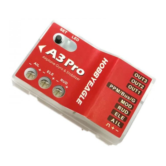
INSTALLATION Use one of the supplied 3M pads to attach the gyro to your plane firmly. For best performance the gyro should be mounted as close to the C.G. as possible, and the housing edges must be aligned exactly parallel to all three rotation axis of the plane. - Page 3 CONNECTION A3 Pro has 5 separate input channels which used to connect to the receiver and 3 output channels for servos, and supports standard receivers, PPM and Futaba’s S.BUS(or S.BUS 2) single-line receivers. [AIL], [ELE] and [RUD] should be connected to aileron, elevator and rudder channels of the receiver. [MOD] is used to change the flight mode using a 3-position switch of the transmitter.
-
Page 4: Ppm, S.bus Single-Line Receiver Connection
Using a single-line receiver (e.g. PPM receiver or Futaba’s S.Bus receiver) all channels are transferred by one single wire which connected to [PPM/Bus/G]. When a single-line receiver type has been selected, A3 Pro will load the default channel assignment to recognize the channels from receiver. The default assignment is: CH1=Aileron, CH2=Elevator, CH3=Throttle, CH4=Rudder, CH5=Flight Mode, CH6=Master Gain. -
Page 5: Flight Mode
FLIGHT MODE A3 Pro provides 6 different flight modes which can be changed by a 3-position switch of the transmitter during flight. GYRO-OFF MODE Solid Red Gyro-Off mode is usually used for testing purpose only. When this mode is selected, the gyro will be deactivated completely. -
Page 6: Gain Adjustment
GAIN ADJUSTMENT There are 3 trimming potentiometers on the front of the A3 Pro. They are used to adjust the basic gain of the gyro for aileron, elevator and rudder separately. Clockwise for increase, anticlockwise for decrease. -
Page 7: Entering The Function Menu
FUNCTION MENU Entering the Function Menu To get into the Function Menu, press the button down and don’t release it until LED lights solid White. Menu Selection In the Function Menu, LED will flash Green several times every 3 seconds in a loop and the number of times LED flashes shows at which function item you are currently. -
Page 8: Travel Limiting
at [OUT1] is always the first one selected after you entering the procedure. When the desired servo has been chosen, move and hold the aileron stick into one direction to change the center position for it, when it reaches the desired position release the aileron stick and wait for about 2 seconds until the LED turns solid violet, the current servo position will be saved as the new neutral automatically. -
Page 9: Level Calibration
LEVEL CALIBRATION When flying in Trainer mode or Auto-Level mode, A3 Pro needs to know the angle of the plane in both roll and pitch directions, this is achieved by calculating the attitude of its own. A small angle deviation caused by installation can lead to an unexpected behavior when flying in Trainer mode or Auto-Level mode. -
Page 10: Option Selection
Small Medium * Large White, 7 flashes 8.1. WING TYPE A3 Pro supports standard fixed-wing, flying-wing (delta-wing) and V-tail. LED Color Description After entering in this function, the color of LED shows you the wing type Standard (default) Solid Red currently selected. -
Page 11: Mount Orientation
Most flying-wings have no rudder, in this case, [RUD] is unnecessary to connect. 8.2. MOUNT ORIENTATION A3 Pro can be mounted flat or upright, and even upside down, however, you LED Color Description have to ensure the arrow on the sticker always point to the heading direction. -
Page 12: Gyro Direction
8.3. FLIGHT MODE This function allows you preset the desired flight mode for each position of LED Color Description the switch. Short press the button when LED is flashing 3 times in the Setup Gyro-Off Mode Solid Red Menu to get into the Position Selection Menu. In this second-level menu, LED will flash Blue several times every 3 seconds in a loop and the number Solid Green Normal Mode... - Page 13 Check the gyro direction in aileron direction Quickly move the right wing downward around the roll axis, the right aileron surface should flap down and the left flap up as shown below. Check the gyro direction in elevator direction Quickly move the nose of the plane downward around the pitch axis, the elevator surface should flap up as shown below. Check the gyro direction in rudder direction Quickly move the nose of the plane to the left around the yaw axis, the rudder surface should flap right as shown below.
-
Page 14: Gain Level
8.5. MAX TILT ANGLE This function is used to setup the maximum allowed tilt angle of the plane LED Color Description when operating in Trainer mode. ±30deg Solid Red After entering in this function, the color of LED shows you the angle ±60deg (default) Solid Green currently selected. -
Page 15: Receiver Menu
RECEIVER MENU The Receiver Menu allows you change the receiver type and program the channel mappings for all input channels. Entering the Receiver Menu To get into the Receiver Menu, press and hold the button while turn on the receiver power supply, release it when LED lights solid Violet. -
Page 16: Accelerometer Calibration
Table 4: RECEIVER MENU (* is the default) Functions Solid Solid Solid Solid Solid Solid Green Blue Green Blue Yellow White Violet LED Status Flashing Flashing Flashing Receiver Type Standard* S.Bus Violet, 1 flash Aileron channel None Violet, 2 flashes Elevator channel None Violet, 3 flashes... -
Page 17: Factory Reset
Enter Factory Reset Mode To reset the A3 Pro to factory settings, press and hold the button while turn on the receiver power supply, release it when LED starts flash Violet quickly. (FYA: You should need to hold the button for at least 8 seconds until the LED quickly blinks... -
Page 18: Specifications
SPECIFICATIONS 32-bit MCU Main Controller Sensors High-precision 3-axis gyroscope and 3-axis accelerometer ±2000dps Gyroscope Scale Range ±4g Accelerometer Scale Range 920uS ~ 2120uS with 1520uS center length / 50~333Hz Input Voltage 4.8V~8.4V Operating Temperature -10℃~50℃ Size 43×27×14mm Weight 10g (excluding wires) * VOLTAGE PROTECTOR It’s recommended to use the supplied 3300uF/16V capacitor to get a more stable and secure working voltage for the gyro.