Siemens SIMATIC ET 200SP Manual
Ha digital input module di 16x24vdc
Hide thumbs
Also See for SIMATIC ET 200SP:
- System manual (320 pages) ,
- Manual (270 pages) ,
- Operating instructions manual (166 pages)
Table of Contents
Table of Contents

Related Manuals for Siemens SIMATIC ET 200SP


Summary of Contents for Siemens SIMATIC ET 200SP
- Page 1 Security information Product overview Wiring SIMATIC Parameters ET 200SP HA Digital Input Module DI 16x24VDC Displays and interrupts HA (6DL1131-6BH00-0PH1) Technical specifications Manual Drivers, parameters, diagnostics messages and address space 05/2017 A5E39265608-AA...
- Page 2 Note the following: WARNING Siemens products may only be used for the applications described in the catalog and in the relevant technical documentation. If products and components from other manufacturers are used, these must be recommended or approved by Siemens. Proper transport, storage, installation, assembly, commissioning, operation and maintenance are required to ensure that the products operate safely and without any problems.
-
Page 3: Table Of Contents
Table of contents Security information............................5 Product overview............................7 Properties of the I/O module DI 16x24VDC HA...............7 Wiring.................................11 Terminal assignment of the I/O module DI 16x24VDC HA............11 Schematic circuit diagram......................13 Parameters..............................15 Parameters of the I/O module DI 16x24VDC HA..............15 Module/channel parameters....................16 Explanation of the module/channel parameters..............18 Displays and interrupts..........................21 Status and error displays of the I/O module DI 16x24VDC HA..........21 Interrupts..........................24... - Page 4 Table of contents Digital Input Module DI 16x24VDC HA (6DL1131-6BH00-0PH1) Manual, 05/2017, A5E39265608-AA...
-
Page 5: Security Information
In order to protect plants, systems, machines and networks against cyber threats, it is necessary to implement – and continuously maintain – a holistic, state-of-the-art industrial security concept. Siemens’ products and solutions only form one element of such a concept. Customer is responsible to prevent unauthorized access to its plants, systems, machines and networks. - Page 6 Security information Conventions Please also observe notes marked as follows: Note A note contains important information on the product described in the documentation, on the handling of the product or on the section of the documentation to which particular attention should be paid.
-
Page 7: Product Overview
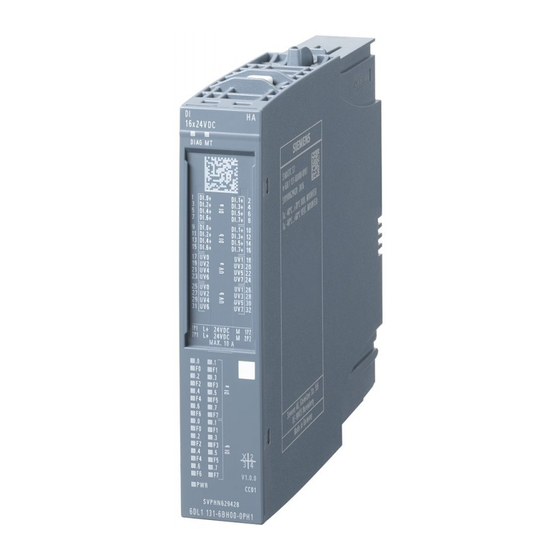
Product overview Properties of the I/O module DI 16x24VDC HA View of the module 16 x2 4V DC DI AG M T 1 DI .0 DI .1 3 DI .2 DI .3 5 DI .4 7 DI .6 DI .5 DI .7 9 DI .0 11 DI .2... - Page 8 Product overview 2.1 Properties of the I/O module DI 16x24VDC HA Properties The I/O module has the following technical properties: ● 16 digital inputs with the following properties that can be individually configured for each channel – Pulse stretching – Diagnostics –...
- Page 9 Product overview 2.1 Properties of the I/O module DI 16x24VDC HA ● Reference identification labels ● Shield connector Digital Input Module DI 16x24VDC HA (6DL1131-6BH00-0PH1) Manual, 05/2017, A5E39265608-AA...
- Page 10 Product overview 2.1 Properties of the I/O module DI 16x24VDC HA Digital Input Module DI 16x24VDC HA (6DL1131-6BH00-0PH1) Manual, 05/2017, A5E39265608-AA...
-
Page 11: Wiring
Wiring Terminal assignment of the I/O module DI 16x24VDC HA Terminal blocks You can operate the I/O module with the following terminal blocks: ● 6DL1193-6TP00-0DH1, light ● 6DL1193-6TP00-0BH1, dark ● 6DL1193-6TP00-0DM1, light, for redundant configuration ● 6DL1193-6TP00-0BM1, dark, for redundant configuration The terminal block is not included in the scope of delivery of the I/O module and must be ordered separately. - Page 12 Wiring 3.1 Terminal assignment of the I/O module DI 16x24VDC HA General pin assignment Table 3-1 Pin assignment of the DI 16×24VDC HA Terminal Assignment Terminal Assignment Explanations DI a /DI.0+ DI a /DI.1+ DI a /DI.n+: Input signal, channel n (0…7) DI a /DI.2+ DI a /DI.3+ DI b /DI.n+: Input signal, channel n+8 (8…15)
-
Page 13: Schematic Circuit Diagram
Wiring 3.2 Schematic circuit diagram Schematic circuit diagram The following figure shows the block diagram of the DI 16×24VDC HA. Figure 3-1 Block diagram DI 16X24VDC HA Digital Input Module DI 16x24VDC HA (6DL1131-6BH00-0PH1) Manual, 05/2017, A5E39265608-AA... - Page 14 Wiring 3.2 Schematic circuit diagram Digital Input Module DI 16x24VDC HA (6DL1131-6BH00-0PH1) Manual, 05/2017, A5E39265608-AA...
-
Page 15: Parameters
Parameters Parameters of the I/O module DI 16x24VDC HA Configuration You configure the I/O module with PCS 7 V9.0 or higher. Parameters You define the functioning of the I/O module via parameters. See also Parameter assignment and structure of the module/channel parameters (Page 35) Digital Input Module DI 16x24VDC HA (6DL1131-6BH00-0PH1) Manual, 05/2017, A5E39265608-AA... -
Page 16: Module/Channel Parameters
Parameters 4.2 Module/channel parameters Module/channel parameters Parameters of the DI 16X24VDC HA You have the following setting options: Table 4-1 Parameters and their defaults Parameter Value range Default Parameter re‐ Efficiency range assignment in Diagnostics, Enabled Module ● Enabled Missing supply voltage L+ ●... - Page 17 Parameters 4.2 Module/channel parameters Parameter Value range Default Parameter re‐ Efficiency range assignment in Hardware interrupts falling ● Enabled Disabled Channel edge ● Disabled Potential group Use potential Module ● Use potential group of the left group of the left module module ●...
-
Page 18: Explanation Of The Module/Channel Parameters
Parameters 4.3 Explanation of the module/channel parameters Explanation of the module/channel parameters Diagnostics, Missing supply voltage L+ Enabling of the diagnostics for missing or insufficient supply voltage L+. IO redundancy You can configure two identical modules redundantly. To do so, plug both modules into a redundant terminal block side by side. - Page 19 Parameters 4.3 Explanation of the module/channel parameters Pulse stretching Pulse stretching is a function for changing a digital input signal. A pulse on a digital input is stretched to at least the configured length. If the input pulse is already longer than the configured length, the pulse is not changed.
- Page 20 Parameters 4.3 Explanation of the module/channel parameters Hardware interrupts negative edge Specifies if a hardware interrupt should be generated for a falling edge. Potential group A potential group consists of a group of directly adjacent I/O modules within an ET 200SP station HA, which are supplied via a common supply voltage.
-
Page 21: Displays And Interrupts
Displays and interrupts Status and error displays of the I/O module DI 16x24VDC HA LED displays The following figure shows the LED displays of the I/O module: 16x24VDC DIAG MT 1 DI.0 DI.1 3 DI.2 DI.3 5 DI.4 DI.5 7 DI.6 DI.7 9 DI.0 DI.1... - Page 22 Displays and interrupts 5.1 Status and error displays of the I/O module DI 16x24VDC HA DIAG LED Table 5-1 Diagnostics display of the DIAG LED DIAG LED Meaning The power supply of the ET 200SP HA is disrupted or switched off. Module is not configured.
- Page 23 Displays and interrupts 5.1 Status and error displays of the I/O module DI 16x24VDC HA LED channel LED channel er‐ Meaning status Process signal = 0 and ● Channel enabled and channel diagnostics pending Process signal = 1 and ● Channel enabled and channel diagnostics pending PWR LED Table 5-4 Status display of the PWR LED...
-
Page 24: Interrupts
Displays and interrupts 5.2 Interrupts Interrupts The I/O module supports diagnostics interrupts, maintenance messages and hardware interrupts. You can find additional information on hardware interrupts in the appendix Hardware interrupts (Page 40) Diagnostics interrupts The I/O module generates a diagnostics interrupt at the following events: ●... -
Page 25: Technical Specifications
Technical specifications Technical specifications of the DI 16X24VDC HA Article number 6DL1131-6BH00-0PH1 General information Product type designation DI 16x24VDC HA HW functional status FS01 Firmware version V1.0 ● FW update possible Usable terminal block TB type H1 and M1 Color code for module-specific color identifica‐ CC01 tion plate Product function... - Page 26 Technical specifications Article number 6DL1131-6BH00-0PH1 2 A; 1 A when mounted vertically; see derating ● up to 60 °C, max. information in Equipment Manual 1 A; See derating information in Equipment Manual ● up to 70 °C, max. 24 V encoder supply ●...
- Page 27 Technical specifications Article number 6DL1131-6BH00-0PH1 Input delay (for rated value of input voltage) for standard inputs Yes; none / 0.05 / 0.1 / 0.4 / 0.8 / 1.6 / 3.2 / 12.8 / – parameterizable 20 ms Cable length 1 000 m ●...
- Page 28 Technical specifications Article number 6DL1131-6BH00-0PH1 70 °C ● horizontal installation, max. ● vertical installation, min. -40 °C 60 °C ● vertical installation, max. Dimensions Width 22.5 mm Height 115 mm Depth 138 mm Weights Weight, approx. 135 g Derating curve The following figure shows the load current derating with horizontal and vertical mounting positions.
- Page 29 Technical specifications Redundancy failover time At an I/O redundancy failover, the update time of the process values or the detection of an edge transition is delayed once by no longer than this time. The maximum redundancy failover time of the I/O module is 55 ms. Digital Input Module DI 16x24VDC HA (6DL1131-6BH00-0PH1) Manual, 05/2017, A5E39265608-AA...
- Page 30 Technical specifications Digital Input Module DI 16x24VDC HA (6DL1131-6BH00-0PH1) Manual, 05/2017, A5E39265608-AA...
-
Page 31: Drivers, Parameters, Diagnostics Messages And Address Space
Drivers, parameters, diagnostics messages and address space Concept of the driver and diagnostics blocks Use outside the PCS 7 environment The following information of the appendix is relevant for use of the ET 200SP HA outside the PCS 7 environment. If you do not plan to operate outside the PCS 7 environment, you do not need the information in the appendix. - Page 32 A.1 Concept of the driver and diagnostics blocks This block concept supports all modules from the list of approved modules. When new Siemens or non-Siemens module types are integrated, the meta-knowledge for the driver generator can be extended by additional XML files (object and action lists).
-
Page 33: Parameter Assignment
Drivers, parameters, diagnostics messages and address space A.2 Parameter assignment Parameter assignment Parameter assignment in the user program You can reconfigure individual channels of the module in RUN without this having an effect on the other channels. Changing parameters in RUN The parameters are transferred to the module with the "WRREC"... - Page 34 Drivers, parameters, diagnostics messages and address space A.2 Parameter assignment Error_ Error_ Cause Remedy Code_ Code_ 0xE1 0x01 Reserved bit set Check and correct the parameters 0xE1 0x02 Invalid diagnostics enable bit set for operating mode 0xE1 0x03 Invalid hardware interrupt enable bit set for operating mode 0xE1 0x07...
-
Page 35: Parameter Assignment And Structure Of The Module/Channel Parameters
Drivers, parameters, diagnostics messages and address space A.3 Parameter assignment and structure of the module/channel parameters Parameter assignment and structure of the module/channel parameters Structure of data record 128 Data record 128 has a length of 76 bytes. It contains module parameters as well as channel or technology parameters of the 16 channels; 4 bytes each. - Page 36 Drivers, parameters, diagnostics messages and address space A.3 Parameter assignment and structure of the module/channel parameters Header information and module parameters The following figure shows the configuration of the header information and module parameters. Figure A-2 Header information and module parameters of data record 128 Digital Input Module DI 16x24VDC HA (6DL1131-6BH00-0PH1) Manual, 05/2017, A5E39265608-AA...
- Page 37 Drivers, parameters, diagnostics messages and address space A.3 Parameter assignment and structure of the module/channel parameters Channel parameters Each channel parameter block contains the cable parameters for the digital input (4 bytes). The following figure shows the configuration of the channel parameters for channels 0 to 15. x = 12 + (channel number * 4);...
-
Page 38: Diagnostics Messages And Maintenance Events
Drivers, parameters, diagnostics messages and address space A.4 Diagnostics messages and maintenance events Diagnostics messages and maintenance events Diagnostics messages A diagnostics message is generated for each diagnostics event and the DIAG LED on the DI 16×24VDC HA flashes red or the MT LED lights up yellow. In addition, channel-specific channel diagnostics are displayed through the corresponding channel error/status LEDs. - Page 39 Drivers, parameters, diagnostics messages and address space A.4 Diagnostics messages and maintenance events Diagnostics mes‐ Error Assignment Meaning Remedy sage code Inconsistent pa‐ Module Errors in the redundancy parameters sent Check the parameter assign‐ rameter assign‐ to the module ment ment Retentive memory Module...
-
Page 40: Hardware Interrupts
Drivers, parameters, diagnostics messages and address space A.5 Hardware interrupts Hardware interrupts Hardware interrupts The DI 16×24VDC HA generates a hardware interrupt for the following events: ● At a rising edge (signal change from 0 to 1) ● At a falling edge (signal change from 1 to 0) Interrupt OBs are called automatically if an interrupt occurs. -
Page 41: Address Space
Drivers, parameters, diagnostics messages and address space A.6 Address space Address space Abbreviations ● "IB" stands for input byte, that is, the module start address in the input area ● "DI" stands for digital input ● "QDIn" stands for the value status (QI) of digital input n Address space The following figure shows the mapping of the address space of the DI 16x24VDC HA. -
Page 42: Address Space Of The Time Stamping (Accuracy 1 Ms)
Drivers, parameters, diagnostics messages and address space A.7 Address space of the time stamping (accuracy 1 ms) Address space of the time stamping (accuracy 1 ms) Address space The following table shows the mapping of the address space of the DI 16x24VDC HA with time stamping (accuracy 1 ms). -
Page 43: Index
Index Channel fault LED, 21 Schematic circuit diagram, 13 Channel parameters, 16, 35 Channel status LED, 21 Conventions, 6 Technology parameters, 35 Terminal block, 11 Data record 128, 35 Header information, 36 DI 16x24VDC HA Value status Accessories, 8 Evaluating, 41 Channel parameters, 16 Functions, 8 Module parameters, 16... - Page 44 Index Digital Input Module DI 16x24VDC HA (6DL1131-6BH00-0PH1) Manual, 05/2017, A5E39265608-AA...