Table of Contents
Quick Links
AC Servo Drives
V
-
Series
USER'S MANUAL
Design and Maintenance
Linear Motor
Analog Voltage and Pulse Train Reference
SGDV SERVOPACK
SGLGW/SGLFW/SGLTW/SGLC/SGT Linear Servomotors
MANUAL NO. SIEP S800000 47G
www.dadehpardazan.ir 88594014-15
Outline
Panel Operator
Wiring and Connection
Trial Operation
Operation
Adjustments
Utility Functions (Fn)
Monitor Displays (Un)
Troubleshooting
Appendix
1
2
3
4
5
6
7
8
9
10
Table of Contents
Troubleshooting

Related Manuals for YASKAWA SGDV SERVOPACK


Summary of Contents for YASKAWA SGDV SERVOPACK
- Page 1 AC Servo Drives Series USER'S MANUAL Design and Maintenance Linear Motor Analog Voltage and Pulse Train Reference SGDV SERVOPACK SGLGW/SGLFW/SGLTW/SGLC/SGT Linear Servomotors Outline Panel Operator Wiring and Connection Trial Operation Operation Adjustments Utility Functions (Fn) Monitor Displays (Un) Troubleshooting Appendix MANUAL NO.
- Page 2 اراﺋﻪ ﺧﺪﻣﺎت ﭘﺸﺘﯿﺒﺎﻧﯽ ﺣﺮﻓﻪ اي و ﺷﺮﮐﺖ داده ﭘﺮدازان ﻫﻮﺷﻤﻨﺪ اﯾﻠﯿﺎ ﺰات ﻬﯿ ﺗﺠ Yaskawa ﺑﺮﮔﺰاري دوره ﻫﺎي آﻣﻮزﺷﯽ PLC – HMI – Servo – Sensor – Inverter – Industrial Network اﻧﺠﺎم ﭘﺮوژﻫﺎي اﺗﻮﻣﺎﺳﯿﻮن ﺻﻨﻌﺘﯽ ﺗﻌﻤﯿﺮات ﺗﺨﺼﺼﯽ ﮐﻠﯿﻪ ادوات اﺗﻮﻣﺎﺳﯿﻮن ﺻﻨﻌﺘﯽ...
- Page 3 Yaskawa. No patent liability is assumed with respect to the use of the information contained herein. Moreover, because Yaskawa is con- stantly striving to improve its high-quality products, the information contained in this manual is subject to change without notice.
-
Page 4: About This Manual
About this Manual This manual describes information required for designing, testing, adjusting, and maintaining -V Series SERVOPACKs. Keep this manual in a location where it can be accessed for reference whenever required. Manuals outlined on the following page must also be used as required by the application. ... -
Page 5: Panel Operator
Notation Used in this Manual • Notation for Reverse Signals The names of reverse signals (i.e., ones that are valid when low) are written with a forward slash (/) before the signal name. Notation Example BK = /BK • Notation for Parameters The notation depends on whether the parameter requires a value setting (parameter for numeric settings) or requires the selection of a function (parameter for selecting functions). - Page 6 Manuals Related to the -V Series Refer to the following manuals as required. Selecting Trial Maintenance Models and Ratings and System Panels and Trial Operation Name Peripheral Specifications Design Wiring Operation and Servo Inspection Devices Adjustment -V Series User's Manual ...
-
Page 7: Safety Precautions
Safety Precautions This section describes important precautions that must be followed during storage, transportation, installation, wiring, operation, maintenance, inspection, and disposal. Be sure to always observe these precautions thor- oughly. WARNING • If you have a pacemaker or any other electronic medical device, do not go near the magnetic way of the servomotor. - Page 8 Storage and Transportation CAUTION • Be sure to store the magnetic way in the package that was used for delivery. • Do not store or install the product in the following locations. Failure to observe this caution may result in fire, electric shock, or damage to the equipment. •...
- Page 9 Installation CAUTION • When unpacking and installing magnetic way, check that no metal fragments or magnetized objects near the magnetic because they may be affected by the magnetic attraction of the magnetic way. Failure to observe this caution may result in injury or damage to the magnetic way's magnets. •...
- Page 10 Wiring CAUTION • Be sure to wire correctly and securely. Failure to observe this caution may result in motor overrun, injury, or malfunction. • Securely tighten the cable connector screws and securing mechanism. If the connector screws and securing mechanism are not secure, they may loosen during operation. •...
- Page 11 Operation CAUTION • Do not stand within the machine's range of motion during operation. Failure to observe this caution may result in injury. • Always use the servomotor and SERVOPACK in one of the specified combinations. Failure to observe this caution may result in fire or malfunction. •...
- Page 12 • The drawings presented in this manual are typical examples and may not match the product you received. • If the manual must be ordered due to loss or damage, inform your nearest Yaskawa representative or one of the offices listed on the back of this manual.
-
Page 13: Warranty
6. Events for which Yaskawa is not responsible, such as natural or human-made disasters (2) Limitations of Liability 1. Yaskawa shall in no event be responsible for any damage or loss of opportunity to the customer that arises due to failure of the delivered product. - Page 14 2. The customer must confirm that the Yaskawa product is suitable for the systems, machines, and equipment used by the customer. 3. Consult with Yaskawa to determine whether use in the following applications is acceptable. If use in the application is acceptable, use the product with extra allowance in ratings and specifications, and provide safety measures to minimize hazards in the event of failure.
-
Page 15: Harmonized Standards
Harmonized Standards North American Safety Standards (UL) UL Standards Model (UL File No.) SERVOPACK SGDV UL508C (E147823) European Directives Model European Directives Harmonized Standards Machinery Directive EN ISO13849-1: 2008 2006/42/EC EN 954-1 EN 55011 /A2 group 1, class A EMC Directive SERVOPACK SGDV... - Page 16 Safety Standards Model Safety Standards Standards EN ISO13849-1: 2008 Safety of Machinery EN 954-1 IEC 60204-1 SERVOPACK SGDV IEC 61508 series Functional Safety IEC 62061 IEC 61800-5-2 IEC 61326-3-1 Safe Performance Items Standards Performance Level IEC 61508 SIL2 Safety Integrity Level IEC 62061 SILCL2...
-
Page 17: Table Of Contents
Contents About this Manual ............iii Safety Precautions. - Page 18 Chapter 3 Wiring and Connection ....... .3-1 3.1 Main Circuit Wiring..........3-2 3.1.1 Main Circuit Terminals .
- Page 19 Chapter 5 Operation ......... .5-1 5.1 Control Method Selection .
- Page 20 5.11 Safety Function ..........5-78 5.11.1 Hard Wire Base Block (HWBB) Function .
- Page 21 Chapter 7 Utility Functions (Fn) ......7-1 7.1 List of Utility Functions ......... . 7-2 7.2 Alarm History Display (Fn000) .
- Page 22 Chapter 9 Troubleshooting ........9-1 9.1 Alarm Displays .
- Page 23 xxii www.dadehpardazan.ir 88594014-15...
-
Page 24: Chapter 1 Outline
Outline 1.1 -V Series SERVOPACKs ........1-2 1.2 Part Names . -
Page 25: V Series Servopacks
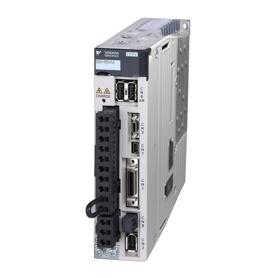
The SERVOPACK makes the most of machine performance in the shortest time possi- ble, thus contributing to improving productivity. Part Names This section describes the part names of SGDV SERVOPACK for analog voltage and pulse train reference. With front cover open Serial number... -
Page 26: Servopack Ratings And Specifications
1.3 SERVOPACK Ratings and Specifications SERVOPACK Ratings and Specifications This section describes the ratings and specifications of SERVOPACKs. 1.3.1 Ratings Ratings of SERVOPACKs are as shown below. (1) SGDV with Single-phase, 100-V Rating SGDV (Single Phase, 100 V) Continuous Output Current [Arms] 0.66 0.91 Instantaneous Max. -
Page 27: Basic Specifications
1 Outline 1.3.2 Basic Specifications 1.3.2 Basic Specifications Basic specifications of SERVOPACKs are shown below. Drive Method Sine-wave current drive with PWM control of IGBT • Absolute linear scale Linear scale pitch of absolute linear scale Signal resolution Number of divisions on absolute linear scale Feedback •... - Page 28 1.3 SERVOPACK Ratings and Specifications (cont’d) Phase A, B, C: line driver Encoder Output Pulse Encoder output pulse: any setting ratio (Refer to 5.3.7.) Fixed Input SEN signal Number of 7 ch Channels • Servo ON (/S-ON) • Proportional control (/P-CON) •...
- Page 29 1 Outline 1.3.2 Basic Specifications (cont’d) Activated when a servo alarm or overtravelling occurs or when the power Dynamic Brake (DB) supply for the main circuit or servomotor is OFF. Regenerative Processing Included Dynamic brake stop, deceleration to a stop, or free run to a stop at P-OT or Overtravel Prevention (OT) N-OT Overcurrent, overvoltage, insufficient voltage, overload, regeneration error,...
-
Page 30: Speed/Position/Force Control
1.3 SERVOPACK Ratings and Specifications 1.3.3 Speed/Position/Force Control The following table shows the basic specifications at speed/position/force control. Control Method Specifications 0 to 10 s (Can be set individually for acceleration and Performance Soft Start Time Setting deceleration.) • Max. input voltage12 V (forward speed reference with positive reference) Reference Voltage •... -
Page 31: Servopack Internal Block Diagrams
1 Outline 1.4.1 Single-phase 100 V, SGDV-R70F05A, -R90F05A, -2R1F05A Models SERVOPACK Internal Block Diagrams 1.4.1 Single-phase 100 V, SGDV-R70F05A, -R90F05A, -2R1F05A Models Analog Servomotor + 12 V Varistor Main circuit – power supply – Dynamic brake circuit Gate drive Temperature Current Relay Gate... -
Page 32: Three-Phase 200 V, Sgdv-R70A05, -R90A05, -1R6A05 Models
1.4 SERVOPACK Internal Block Diagrams 1.4.3 Three-phase 200 V, SGDV-R70A05 , -R90A05 , -1R6A05 Models Analog ∗ Servomotor + 12 V Varistor Main circuit – power supply Dynamic brake circuit Gate drive Current Voltage Relay Voltage Gate Temperature overcurrent sensor... -
Page 33: Three-Phase 200 V, Sgdv-3R8A05A, -5R5A05A, -7R6A05A Models
1 Outline 1.4.5 Three-phase 200 V, SGDV-3R8A05A, -5R5A05A, -7R6A05A Models 1.4.5 Three-phase 200 V, SGDV-3R8A05A, -5R5A05A, -7R6A05A Models Analog Servomotor Varistor ± 12 V Main circuit – power supply Dynamic brake circuit Gate drive Current Voltage Relay Voltage Gate Temperature overcurrent drive sensor... -
Page 34: Three-Phase 200 V, Sgdv-180A05A, -200A05A Models
1.4 SERVOPACK Internal Block Diagrams 1.4.7 Three-phase 200 V, SGDV-180A05A, -200A05A Models Analog Fan 1 Fan 2 Servomotor Varistor ± 12 V ± 12 V Main circuit – power supply Overheat protector, Dynamic overcurrent protector brake circuit Current Voltage Relay Voltage Gate drive sensor... -
Page 35: Three-Phase 200 V, Sgdv-550A05A Models
1 Outline 1.4.9 Three-phase 200 V, SGDV-550A05A Models 1.4.9 Three-phase 200 V, SGDV-550A05A Models Analog Fan 1 Fan 2 Fan 3 Servomotor Varistor ± 12 V ± 12 V ± 12 V Main circuit – power supply Overheat protector, Dynamic overcurrent protector brake circuit Current... -
Page 36: Three-Phase 400 V, Sgdv-8R4D05A, -120D05A Models
1.4 SERVOPACK Internal Block Diagrams 1.4.11 Three-phase 400 V, SGDV-8R4D05A, -120D05A Models Analog Fan 1 Fan 2 Servomotor Varistor ± 12 V ± 12 V – Main circuit power supply – Overheat protector, Dynamic overcurrent protector brake circuit Current Relay Voltage Gate drive... -
Page 37: Three-Phase 400 V, Sgdv-260D05A Model
1 Outline 1.4.13 Three-phase 400 V, SGDV-260D05A Model 1.4.13 Three-phase 400 V, SGDV-260D05A Model Analog Fan 1 Fan 2 Fan 3 Servomotor +24 V +24 V +24 V Varistor – Main circuit power supply – Overheat protector, Dynamic overcurrent protector brake circuit Current Voltage... -
Page 38: Examples Of Servo System Configurations
1.5 Examples of Servo System Configurations Examples of Servo System Configurations This section describes examples of basic servo system configuration. 1.5.1 Connecting to SGDV- F05A SERVOPACK Power supply Single-phase 100 VAC Molded-case circuit breaker (MCCB) Protects the power line by shutting the circuit OFF when overcurrent is detected. -
Page 39: Connecting To Sgdv-A05 Servopack
1 Outline 1.5.2 Connecting to SGDV-A05 SERVOPACK 1.5.2 Connecting to SGDV-A05 SERVOPACK (1) Using a Three-phase, 200-V Power Supply Power supply Three-phase 200 VAC R S T Molded-case circuit breaker (MCCB) Protects the power line by shutting the circuit OFF when overcurrent is detected. - Page 40 1.5 Examples of Servo System Configurations (2) Using a Single-phase, 200-V Power Supply The -V Series 200 V SERVOPACK generally specifies a three-phase power input but some models can be used with a single-phase 200 V power supply. Refer to 3.1.3 Using the SERVOPACK with Single-phase, 200 V Power Input for details.
-
Page 41: Connecting To Sgdv-D05A Servopack
1 Outline 1.5.3 Connecting to SGDV-D05A SERVOPACK 1.5.3 Connecting to SGDV-D05A SERVOPACK Power supply Three-phase 400 VAC R S T Molded-case circuit breaker (MCCB) Protects the power line by shutting the circuit OFF when overcurrent is detected. Noise filter Digital Eliminates operator external noise from... -
Page 42: Servopack Model Designation
1.6 SERVOPACK Model Designation SERVOPACK Model Designation This section shows SERVOPACK model designation. 8th + 9th + 13th 11th + 12th 1st + 2nd + 4th 7th 5th + 6th digit digits 10th digits digit digit 3rd digits digits SGDV –... -
Page 43: Inspection And Maintenance
Refer to the standard replacement period in the following table and contact your Yaskawa representative. After an examination of the part in question, we will determine whether the parts should be replaced or not. -
Page 44: Chapter 2 Panel Operator
Panel Operator 2.1 Overview ..........2-2 2.1.1 Names and Functions . -
Page 45: Overview
2 Panel Operator 2.1.1 Names and Functions Overview 2.1.1 Names and Functions Panel operator consists of display part and keys. Parameter setting, status display, execution of utility function, and monitoring of the SERVOPACK operation are enabled using the panel operator. The names and functions of the keys on the panel operator are as follows. -
Page 46: Status Display
2.1 Overview 2.1.3 Status Display The display shows the following status. Analog Bit Data Code Code Meaning Code Meaning Baseblock Reverse Run Prohibited Servo OFF (servomotor power OFF) N-OT is OFF. Safety Function The SERVOPACK is baseblocked by the Servo ON (servomotor power ON) safety function. -
Page 47: Utility Functions (Fn)
2 Panel Operator Utility Functions (Fn) The utility functions are related to the setup and adjustment of the SERVOPACK. In this case, the panel operator displays numbers beginning with Fn. Analog Display Example for Origin Search The following table outlines the procedures necessary for an origin search (Fn003). Display after Step Keys... -
Page 48: Parameters (Pn)
2.3 Parameters (Pn) Parameters (Pn) This section describes the classifications, methods of notation, and settings for parameters given in this man- ual. 2.3.1 Parameter Classification Parameters of the -V Series SERVOPACK are classified into two types of parameters. One type of parame- ters is required for setting up the basic conditions for operation and the other type is required for tuning param- eters that are required to adjust servomotor characteristics. -
Page 49: Setting Parameters
2 Panel Operator 2.3.3 Setting Parameters • Notation Example Analog Panel Operator Display (Display Example for Pn002) Digit Notation Setting Notation Notation Meaning Notation Meaning Indicates the value for the Indicates that the value for the Pn002.0 = x Pn002.0 1st digit 1st digit of parameter Pn002. - Page 50 2.3 Parameters (Pn) Parameters with Setting Ranges of Six Digits or More Panel operator displays five digits. When the parameter number is more than six digits, values are displayed and set as shown below. Analog Leftmost flash display shows digit's position.
- Page 51 2 Panel Operator 2.3.3 Setting Parameters (cont’d) Display after Step Keys Operation Operation Press the MODE/SET Key to save the value to the SER- VOPACK. During saving, top two digits flash. After the saving is completed, press the DATA/SHIFT Key for MODE/SET DATA/ approximately one second.
-
Page 52: Monitor Displays (Un)
2.4 Monitor Displays (Un) Monitor Displays (Un) The monitor displays can be used for monitoring the reference values, I/O signal status, and SERVOPACK internal status. For details, refer to 8.2 Viewing Monitor Displays. The panel operator displays numbers beginning with Un. Analog ... - Page 53 2 Panel Operator 2-10 www.dadehpardazan.ir 88594014-15...
-
Page 54: Chapter 3 Wiring And Connection
Wiring and Connection 3.1 Main Circuit Wiring ......... . 3-2 3.1.1 Main Circuit Terminals . -
Page 55: Main Circuit Wiring
3 Wiring and Connection 3.1.1 Main Circuit Terminals Main Circuit Wiring The names and specifications of the main circuit terminals are given below. Also this section describes the general precautions for wiring and precautions under special environments. 3.1.1 Main Circuit Terminals : Main circuit terminals Terminal Name... -
Page 56: Using A Standard Power Supply (Single-Phase 100 V, Three-Phase 200 V, Or Three-Phase 400 V)
3.1 Main Circuit Wiring (cont’d) Terminal Name Model SGDV- Specification Symbols DC reactor connec- If a countermeasure against power supply harmonic A tion terminal for pow- waves is needed, connect a DC reactor between D er supply harmonic suppression A Main circuit positive D terminal... - Page 57 3 Wiring and Connection 3.1.2 Using a Standard Power Supply (Single-phase 100 V, Three-phase 200 V, or Three-phase 400 V) (2) Main Circuit Wires This section describes the main circuit wires for SERVOPACKs. • The specified wire sizes are for use when the three lead cables are bundled and when the rated electric current is applied with a surrounding air temperature of 40C.
- Page 58 3.1 Main Circuit Wiring (3) Typical Main Circuit Wiring Examples Note the following points when designing the power ON sequence. • Design the power ON sequence so that main power is turned OFF when a servo alarm signal (ALM) is output. •...
- Page 59 3 Wiring and Connection 3.1.2 Using a Standard Power Supply (Single-phase 100 V, Three-phase 200 V, or Three-phase 400 V) Three-phase 200 V, SGDV- • SGDV-R70A, -R90A, -1R6A, -2R8A, -3R8A, -5R5A, -7R6A, -120A, -180A, -200A, -330A Analog R S T SERVOPACK SGDV- 1FLT...
- Page 60 3.1 Main Circuit Wiring Three-phase 400 V, SGDV- • SGDV-1R9D, -3R5D, -5R4D, -8R4D, -120D, -170D Analog R S T SERVOPACK SGDV- 1FLT DC power 24 V supply − (For servo +24 V alarm display) − Servo power Servo power supply ON supply OFF 1QF: Molded-case circuit breaker...
- Page 61 3 Wiring and Connection 3.1.2 Using a Standard Power Supply (Single-phase 100 V, Three-phase 200 V, or Three-phase 400 V) (4) Power Supply Capacities and Power Losses The following table shows the SERVOPACK’s power supply capacities and power losses. Maximum Main Main Power Supply...
- Page 62 3.1 Main Circuit Wiring (5) How to Select Molded-case Circuit Breaker and Fuse Capacities The following table shows the SERVOPACK’s current capacities and inrush current. Select a molded-case circuit breaker and fuses in accordance with these specifications. Maximum Power Sup- Current Capacity Inrush Current Main...
-
Page 63: Using The Servopack With Single-Phase, 200 V Power Input
3 Wiring and Connection 3.1.3 Using the SERVOPACK with Single-phase, 200 V Power Input 3.1.3 Using the SERVOPACK with Single-phase, 200 V Power Input Some models of -V series three-phase 200 V power input SERVOPACK can be used also with a single-phase 200 V power supply. - Page 64 3.1 Main Circuit Wiring (4) Wiring Example with Single-phase 200-V Power Supply Input SERVOPACK with Single-phase, 200-V Power Supply Applicable SERVOPACK Model: SGDV-R70A, -R90A, -1R6A, -2R8A, and -5R5A Analog SERVOPACK SGDV- 1FLT +24 V (For servo alarm display) − Servo power Servo power supply ON...
- Page 65 3 Wiring and Connection 3.1.3 Using the SERVOPACK with Single-phase, 200 V Power Input (6) How to Select Molded-case Circuit Breaker and Fuse Capacities The following table shows the SERVOPACK’s current capacities and inrush current when using single-phase 200 V power supply. Select a molded-case circuit breaker and fuses in accordance with these specifications. Maximum Current Capacity Inrush Current...
-
Page 66: Using The Servopack With A Dc Power Input
3.1 Main Circuit Wiring 3.1.4 Using the SERVOPACK with a DC Power Input (1) Parameter Setting When using a DC power supply, make sure to set the parameter Pn001.2 to 1 (DC power input supported) before inputting DC power. Parameter Meaning When Enabled Classification n.0... - Page 67 3 Wiring and Connection 3.1.4 Using the SERVOPACK with a DC Power Input (3) Wiring Example with DC Power Supply Input 200-V SERVOPACK SGDV-A R S T Analog 200-V SERVOPACK SGDV- 1FLT AC/DC +24 V (For servo alarm display) −...
-
Page 68: Using More Than One Servopack
3.1 Main Circuit Wiring 3.1.5 Using More Than One SERVOPACK This section shows an example of the wiring and the precautions when more than one SERVOPACK is used. (1) Wiring Example Connect the alarm output (ALM) terminals for three SERVOPACKs in series to enable alarm detection relay 1RY to operate. -
Page 69: General Precautions For Wiring
3 Wiring and Connection 3.1.6 General Precautions for Wiring 3.1.6 General Precautions for Wiring • Use a molded-case circuit breaker (1QF) or fuse to protect the main circuit. The SERVOPACK connects directly to a commercial power supply; it is not isolated through a transformer or other device.... -
Page 70: I/O Signal Connections
3.2 I/O Signal Connections I/O Signal Connections This section describes the names and functions of I/O signals (CN1). Also connection examples by control method are shown. 3.2.1 I/O Signal (CN1) Names and Functions The following table shows the names and functions of I/O signals (CN1). (1) Input Signals Refer- Control... - Page 71 3 Wiring and Connection 3.2.1 I/O Signal (CN1) Names and Functions (cont’d) Refer- Control Signal Pin No. Function ence Method Name Section PULS Input pulse modes: Select one of them. /PULS • Sign + pulse train 5.4.1 SIGN • Forward + Reverse pulse train Position /SIGN •...
-
Page 72: Safety Function Signal (Cn8) Names And Functions
3.2 I/O Signal Connections 3.2.2 Safety Function Signal (CN8) Names and Functions The following table shows the terminal layout of safety function signals (CN8). Signal Name Pin No. Function /HWBB1+ Hard wire baseblock input 1 For hard wire baseblock input. /HWBB1- Baseblock (motor current off) when /HWBB2+... -
Page 73: Example Of I/O Signal Connections In Speed Control
3 Wiring and Connection 3.2.3 Example of I/O Signal Connections in Speed Control 3.2.3 Example of I/O Signal Connections in Speed Control Connection example in speed control is as shown below. SERVOPACK Speed reference (Max. input V-REF voltage range: ALO1 ±... -
Page 74: Example Of I/O Signal Connections In Position Control
3.2 I/O Signal Connections 3.2.4 Example of I/O Signal Connections in Position Control Connection example in position control is as shown below. SERVOPACK 150 Ω PULS PULS ALO1 Reverse /PULS Phase A Alarm code output (OFF for alarm) ALO2 Max. operating voltage: 30 VDC 150 Ω... -
Page 75: Example Of I/O Signal Connections In Force Control
3 Wiring and Connection 3.2.5 Example of I/O Signal Connections in Force Control 3.2.5 Example of I/O Signal Connections in Force Control Connection example in force control is as shown below. SERVOPACK External speed limit V-REF ALO1 (Max. input Alarm code output (OFF for alarm) voltage range: ALO2 Max. -
Page 76: I/O Signal Allocations
3.3 I/O Signal Allocations I/O Signal Allocations This section describes the I/O signal allocations. 3.3.1 Input Signal Allocations In most cases, input signals can be used at the factory settings. Input signals can also be allocated as required. (1) Using Factory Settings Items in cells with bold lines in the following table are the factory-set signal allocations. - Page 77 3 Wiring and Connection 3.3.1 Input Signal Allocations Input signal allocation at factory setting can be checked using the parameters Pn50A and Pn50B. Analog Pn50A Uses input terminal with factory setting. Allocates /S-ON signal to CN1-40. Allocates /P-CON signal to CN1-41. Allocates /P-OT signal to CN1-42.
- Page 78 3.3 I/O Signal Allocations Connection Not Required CN1 Pin Numbers (SERVOPACK judges Input Signal Names Validity Input Sig- the connection) and Parameters Level Always Always /S-ON Servo ON Pn50A.1 S-ON /P-CON Proportional Operation Reference P-CON Pn50A.2 P-OT Forward Run Prohibited Pn50A.3 /P-OT N-OT...
- Page 79 3 Wiring and Connection 3.3.1 Input Signal Allocations (3) Example of Input Signal Allocation The procedure to replace Servo ON (/S-ON) signal allocated on CN1-40 and Forward External Force Limit (/ P-CL) allocated on CN1-45 is shown below. Pn50A Pn50B Before After Display after Opera-...
-
Page 80: Output Signal Allocations
3.3 I/O Signal Allocations Input signal polarities are as follows when sequence input circuit is connected to a sink circuit. If connected to a source circuit, polarities are reversed. For details, refer to 3.4.2 Sequence Input Circuit. Signal Level Voltage Level... - Page 81 3 Wiring and Connection 3.3.2 Output Signal Allocations (2) Changing Output Signal Allocations • The signals not detected are considered as "Invalid." For example, Positioning Com- pletion (/COIN) signal in speed control is "Invalid." • Inverting the polarity of the brake signal (/BK), i.e. positive logic, will prevent the hold- ing brake from working in case of its signal line disconnection....
- Page 82 3.3 I/O Signal Allocations (3) Example of Output Signal Allocation The procedure to set Movement Detection (/TGON) signal of factory setting to Invalid and allocate Brake " " Interlock (/BK) signal is shown below. Pn50E Pn50F Before After Display after Opera- Step Keys Operation...
-
Page 83: Examples Of Connection To Host Controller
3 Wiring and Connection 3.4.1 Reference Input Circuit Examples of Connection to Host Controller This section shows examples of SERVOPACK I/O signal connection to the host controller. 3.4.1 Reference Input Circuit (1) Analog Input Circuit CN1 connector terminals, 5-6 (speed reference input) and 9-10 (force reference input) are explained below. Analog signals are either speed or force reference signals at the impedance below. - Page 84 3.4 Examples of Connection to Host Controller • Precaution when host controller uses open collectors with customer-supplied power. Before wiring, confirm that the specifications of the host controller satisfy the values shown in the following table. If these conditions are not satisfied, the SERVOPACK may malfunction. Pull-up voltage (Vcc) Pull-up resistance (R1) 24 V...
-
Page 85: Sequence Input Circuit
3 Wiring and Connection 3.4.2 Sequence Input Circuit 3.4.2 Sequence Input Circuit (1) Photocoupler Input Circuit CN1 connector terminals 40 to 47 are explained below. The sequence input circuit interface is connected through a relay or open-collector transistor circuit. When connecting through a relay, use a low-current relay. - Page 86 3.4 Examples of Connection to Host Controller (2) Safety Input Circuit As for wiring input signals for safety function, input signals make common 0 V. It is necessary to make an input signal redundant. Input Signal Connection Example SERVOPACK 24-V power supply Switch /HWBB1+ 4 3.3 kΩ...
-
Page 87: Sequence Output Circuit
3 Wiring and Connection 3.4.3 Sequence Output Circuit 3.4.3 Sequence Output Circuit Four types of SERVOPACK output circuit are available. Incorrect wiring or incorrect voltage application to the output circuit may cause short-cir- cuit. If a short-circuit occurs as a result of any of these causes, the holding brake will not work. - Page 88 3.4 Examples of Connection to Host Controller (3) Line Driver Output Circuit CN1 connector terminals, 33-34 (phase-A signal), 35-36 (phase-B signal), and 19-20 (phase-C signal) are explained below. These terminals output the following signals via the line-driver output circuits. • Output signals for which linear scale’s serial data is converted as two phases pulses (PAO, /PAO, PBO, / PBO) •...
-
Page 89: Linear Scale Connection
3 Wiring and Connection 3.5.1 Linear Scale Signal (CN2) Names and Functions Linear Scale Connection This section describes the linear scale signal (CN2) names, functions, and connection examples. 3.5.1 Linear Scale Signal (CN2) Names and Functions The following table shows the names and functions of linear scale signals (CN2). Signal Name Pin No. - Page 90 3.5 Linear Scale Connection (2) Model Designations The following figure shows the model designations of the serial converter unit. JZDP - Linear Serial Converter Unit Model Applicable Linear Servomotor Servomotor Model Symbol Servomotor Model Symbol Applicable Linear Code Hall Sensor Scale 30 A 050 C 20 A 170 A...
- Page 91 3 Wiring and Connection 3.5.2 Serial Converter Unit (3) Analog Signal Input Timing The following figure shows the input timing of the analog signals. When the cos and sin signals are shifted 180 degrees, the differential signals are produced as the /cos and /sin signals.
-
Page 92: Linear Scale Connection Examples
3.5 Linear Scale Connection 3.5.3 Linear Scale Connection Examples The following diagrams show connection examples of the linear scale, the SERVOPACK, and the host con- troller. (1) Incremental Linear Scale Linear Scale Made by Heidenhain Linear scale Host controller Serial converter unit made by Heidenhain SERVOPACK... - Page 93 3 Wiring and Connection 3.5.3 Linear Scale Connection Examples Linear Scale by Magnescale Co., Ltd. • SR75, SR85 Linear scale by Host controller Magnescale Co., Ltd. SERVOPACK ∗ Phase A /PAO Phase A Phase B Phase B /PBO Phase C Phase C /PCO Output line-driver...
- Page 94 3.5 Linear Scale Connection • SL700, SL710, SL720, SL730 • Head with interpolator PL101-RY Host controller Interpolator Linear scale SERVOPACK ∗ Head ∗ Phase A Phase A /PAO Connection cable Phase B made by Magnescale Phase B /PBO Co., Ltd. Phase C Phase C /PCO...
- Page 95 3 Wiring and Connection 3.5.3 Linear Scale Connection Examples (2) Absolute Linear Scale Linear Scale Made by Mitutoyo Absolute linear scale Host controller SERVOPACK made by Mitutoyo ∗ ∗ Phase A Phase A /PAO Phase B Phase B /PBO Phase C Phase C /PCO...
-
Page 96: Connecting Regenerative Resistors
3.6 Connecting Regenerative Resistors Connecting Regenerative Resistors If the built-in regenerative resistor is insufficient, connect an external regenerative resistor by one of the fol- lowing methods and set the regenerative resistor capacity (Pn600). As for precautions on selecting a regenera- ... - Page 97 3 Wiring and Connection 3.6.1 Connecting Regenerative Resistors (3) SERVOPACKs: Model SGDV-550A and -260D No built-in regenerative resistor is provided, so the external regenerative resistor is required. The regenerative resistor units are as follows: Note: The regenerative resistor unit is constructed from a number of resistors. Applicable Applicable Main Circuit...
-
Page 98: Setting Regenerative Resistor Capacity
Note 1. If Pn600 is not set to the optimum value, alarm A.320 will occur. 2. When set to the factory setting (Pn600 = 0), the SERVOPACK’s built-in resistor or Yaskawa’s regenerative resis- tor unit has been used. -
Page 99: Noise Control And Measures For Harmonic Suppression
3 Wiring and Connection 3.7.1 Wiring for Noise Control Noise Control and Measures for Harmonic Suppression This section describes the wiring for noise control and the DC reactor for harmonic suppression. 3.7.1 Wiring for Noise Control • Because the SERVOPACK is designed as an industrial device, it provides no mecha- nism to prevent noise interference. - Page 100 3.7 Noise Control and Measures for Harmonic Suppression (1) Noise Filter The SERVOPACK has a built-in microprocessor (CPU), so protect it from external noise as much as possible by installing a noise filter in the appropriate place. The following is an example of wiring for noise control. SERVOPACK Noise filter ∗3 Servomotor...
-
Page 101: Precautions On Connecting Noise Filter
3 Wiring and Connection 3.7.2 Precautions on Connecting Noise Filter 3.7.2 Precautions on Connecting Noise Filter This section describes the precautions on installing a noise filter. (1) Precautions on Using Noise Filters Always observe the following installation and wiring instructions. Some noise filters have large leakage currents. -
Page 102: Connecting A Reactor For Harmonic Suppression
3.7 Noise Control and Measures for Harmonic Suppression Connect the noise filter ground wire directly to the ground plate. Do not connect the noise filter ground wire to other ground wires. Correct Incorrect Noise Noise Filter Filter SERVOPACK SERVOPACK SERVOPACK SERVOPACK Shielded ground wire Ground plate... - Page 103 3 Wiring and Connection 3.7.3 Connecting a Reactor for Harmonic Suppression 3-50 www.dadehpardazan.ir 88594014-15...
-
Page 104: Chapter 4 Trial Operation
Trial Operation 4.1 Inspection and Checking before Trial Operation ....4-2 4.2 Trial Operation for Servomotor without Load ..... . 4-2 4.3 Trial Operation for Servomotor without Load from Host Reference . -
Page 105: Inspection And Checking Before Trial Operation
4 Trial Operation Inspection and Checking before Trial Operation To ensure safe and correct trial operation, inspect and check the following items before starting trial operation. (1) Servomotors Inspect and check the following items, and take appropriate measures before performing trial operation if any problem exists. -
Page 106: Trial Operation For Servomotor Without Load From Host Reference
4.3 Trial Operation for Servomotor without Load from Host Reference Trial Operation for Servomotor without Load from Host Reference Check the following items before performing trial operation of the servomotor without load from host refer- ence. • Check that servomotor operation reference input from the host controller to the SERVOPACK and I/O sig- nals are set properly. -
Page 107: Inspecting Connection And Status Of Input Signals
4 Trial Operation 4.3.1 Inspecting Connection and Status of Input Signals 4.3.1 Inspecting Connection and Status of Input Signals Check the items in step 1 before trial operation of the servomotor under speed control and position control ref- erences from the host controller. Check the connection and status of input signals using the following procedure. - Page 108 4.3 Trial Operation for Servomotor without Load from Host Reference (cont’d) Step Operation Reference Input the /S-ON signal, then make sure that the display of the panel operator is as shown below. 9.1 Alarm Displays If an alarm display appears, correct it according to 9.1 Alarm Displays. If the cause of alarm is not corrected, the servo ON signal cannot be input and the servomotor cannot be turned on.
-
Page 109: Trial Operation In Speed Control
4 Trial Operation 4.3.2 Trial Operation in Speed Control Slide the lock injector of the safety function’s jumper connector to the SERVOPACK side to unlock and remove the safety function’s jumper connector. Enlarged View 1. Slide the lock injector to the SERVOPACK side. -
Page 110: Trial Operation Under Position Control From The Host Controller
4.3 Trial Operation for Servomotor without Load from Host Reference 4.3.3 Trial Operation under Position Control from the Host Controller with the SERVOPACK Used for Speed Control To operate the SERVOPACK in speed control under the position control from the host controller, check the operation of the servomotor after finishing the trial operation explained in 4.3.2 Trial Operation in Speed Con- trol Step... -
Page 111: Trial Operation In Position Control
4 Trial Operation 4.3.4 Trial Operation in Position Control 4.3.4 Trial Operation in Position Control Perform the following steps for trial operation in position control. The steps are specified on the condition that input signal wiring for the position control has been completed according to 4.3.1 Inspecting Connection and Sta- tus of Input Signals. -
Page 112: Trial Operation With The Servomotor Connected To The Machine
4.4 Trial Operation with the Servomotor Connected to the Machine Trial Operation with the Servomotor Connected to the Machine Perform the following steps for trial operation when the servomotor is connected to the machine. The steps are specified on the condition that trial operation for servomotor without load has been completed in each control method. - Page 113 4 Trial Operation (cont’d) Step Operation Reference Perform trial operation with the servomotor connected to the machine, following each section in 4.3 Trial Operation for Servomotor without Load from Host Refer- 4.3 Trial Operation for ence. Servomotor without Load from Host Reference Check that the trial operation is completed with as the trial operation for servomotor without load.
-
Page 114: Test Without Motor Function
4.5 Test Without Motor Function Test Without Motor Function The test without a motor is used to check the operation of the host controller and peripheral devices by simu- lating the operation of the servomotor in the SERVOPACK, i.e., without actually operating a servomotor. This function enables you to check wiring, verify the system while debugging, and verify parameters, thus shorten- ing the time required for setup work and preventing damage to the machine that may result from possible mal- functions. -
Page 115: Limitations
4 Trial Operation 4.5.3 Limitations 4.5.3 Limitations The following functions cannot be used during the test without a motor. • Regeneration and dynamic brake operation • Brake output signal (The brake output signal can be checked with the I/O signal monitor function of the Sig- maWin+.) •... -
Page 116: Operator Displays During Testing Without Motor
4.5 Test Without Motor Function 4.5.4 Operator Displays during Testing without Motor The status display changes as shown below to show that the test without a motor is being executed. (1) Display on Panel Operator The test without a motor operation in progress is indicated with tSt. Analog ... - Page 117 4 Trial Operation 4.5.4 Operator Displays during Testing without Motor 4-14 www.dadehpardazan.ir 88594014-15...
-
Page 118: Chapter 5 Operation
Operation 5.1 Control Method Selection ........5-3 5.2 Basic Functions Settings . - Page 119 5 Operation 5.6 Internal Set Speed Control ........5-56 5.6.1 Basic Settings for Speed Control with an Internal Set Speed .
-
Page 120: Control Method Selection
5.1 Control Method Selection Control Method Selection The control method supported by the SGDV SERVOPACK are described below. The control method can be selected with parameter Pn000. Control Method Selection Reference Pn.000.1 Control Description Section Controls servomotor speed by means of an analog voltage speed reference. -
Page 121: Basic Functions Settings
5 Operation 5.2.1 Servo ON Signal Basic Functions Settings 5.2.1 Servo ON Signal This sets the servo ON signal (/S-ON) that determines whether the servomotor power is ON or OFF. (1) Signal Setting Connector Type Name Setting Meaning Pin Number Servomotor power is ON. - Page 122 5.2 Basic Functions Settings (1) Factory-set Input Signal Allocations (Pn50A.0 = 0) If the factory settings are used to allocate the input signals (Pn50A.0 = 0), polarity detection will start when the servo ON signal (/S-ON) is ON. The servo ready signal (/S-RDY) will be ON after polarity detection has been completed, and the servo ON signal remains ON.
-
Page 123: Servomotor Movement Direction
5 Operation 5.2.3 Servomotor Movement Direction When the polarity detection signal is set to be always enabled, polarity detection will automatically start when the main circuit power supply is turned ON. If so, safety mea- sures must be taken, because the operations of servomotor can become unpredictable. 5.2.3 Servomotor Movement Direction The servomotor movement direction can be reversed with parameter Pn000.0 without changing the polarity of... -
Page 124: Overtravel
5.2 Basic Functions Settings 5.2.4 Overtravel The overtravel limit function forces movable machine parts to stop if they exceed the allowable range of motion and turn ON a limit switch. CAUTION • Installing limit switches For machines that move using linear motion, connect limit switches to P-OT and N-OT of CN1 as shown below to prevent machine damage. - Page 125 5 Operation 5.2.4 Overtravel (2) Overtravel Function Setting Parameters Pn50A and Pn50B can be set to enable or disable the overtravel function. If the overtravel function is not used, no wiring for overtravel input signals will be required. When Parameter Meaning Classification Enabled...
- Page 126 5.2 Basic Functions Settings When Servomotor Stopping Method is Set to Decelerate to Stop Emergency stop force can be set with Pn406. Force Emergency Stop Force Speed Position Classification Pn406 Setting Range Setting Unit Factory Setting When Enabled 0 to 800 Immediately Setup...
-
Page 127: Holding Brakes
5 Operation 5.2.5 Holding Brakes 5.2.5 Holding Brakes A holding brake is a brake used to hold the position of the movable part of the machine when the SERVO- PACK is turned OFF so that movable part does not move due to gravity or external forces. The brake is not included, so if necessary, install a holding brake on the machine. - Page 128 5.2 Basic Functions Settings (1) Wiring Example Use the brake signal (/BK) and the brake power supply to form a brake ON/OFF circuit. The following dia- gram shows a standard wiring example. The timing can be easily set using the brake signal (/BK). SERVOPACK Servomotor Power supply...
- Page 129 5 Operation 5.2.5 Holding Brakes (2) Brake Signal (/BK) Setting This output signal controls the brake. The output signal must be allocated with Pn50F. Refer to (3) Brake Sig- nal (/BK) Allocation for allocation. The /BK signal turns OFF (applies the brake) when an alarm is detected or the /S-ON signal is turned OFF. The brake OFF timing can be adjusted with Pn506.
- Page 130 5.2 Basic Functions Settings The servomotor will turn OFF immediately when an alarm occurs, regardless of the set- ting of this parameter. The machine movable part may shift due to gravity or external force before the brake operates. (5) Brake Signal (/BK) Output Timing during Servomotor Movement If an alarm occurs while the servomotor is moving, the servomotor will come to a stop and the brake signal ...
-
Page 131: Stopping Servomotors After /S-On Turned Off Or Alarm Occurrence
5 Operation 5.2.6 Stopping Servomotors after /S-ON Turned OFF or Alarm Occurrence 5.2.6 Stopping Servomotors after /S-ON Turned OFF or Alarm Occurrence The servomotor stopping method can be selected after the /S-ON (Servo ON) signal turns OFF or an alarm occurs. - Page 132 5.2 Basic Functions Settings (2) Stopping Method for Servomotor When an Alarm Occurs There are two types of alarms (Gr.1 and Gr.2) that depend on the stopping method when an alarm occurs. Select the stopping method for the servomotor when an alarm occurs using Pn001.0 and Pn00B.1. The stopping method for the servomotor for a Gr.1 alarm is set to Pn001.0.
-
Page 133: Instantaneous Power Interruption Settings
5 Operation 5.2.7 Instantaneous Power Interruption Settings 5.2.7 Instantaneous Power Interruption Settings Determines whether to continue operation or turn OFF the servomotor’s power when the power supply voltage to the SERVOPACK's main circuit is interrupted. Instantaneous Power Cut Hold Time Position Speed Force... -
Page 134: Semi F47 Function
5.2 Basic Functions Settings 5.2.9 SEMI F47 Function (Force Limit Function for Low DC Power Supply Voltage for Main Circuit) The force limit function detects an undervoltage warning and limits the output current if the DC power supply voltage for the main circuit in the SERVOPACK drops to a specified value because the power was momen- tarily interrupted or the power supply voltage for the main circuit was temporality lowered. - Page 135 5 Operation 5.2.9 SEMI F47 Function (Force Limit Function for Low DC Power Supply Voltage for Main Circuit) (1) Execution Method This function can be executed either with the host controller and the SERVOPACK or with the SERVOPACK only. With the Host Controller and the SERVOPACK The host controller limits the force in response to an undervoltage warning....
- Page 136 5.2 Basic Functions Settings (2) Related Parameters Parameter Meaning When Enabled Classification n.0 Does not detect undervoltage. [Factory setting] Pn008 n.1 Detects warning and limits force by host controller. After restart Setup Detects warning and limits force by Pn424 and Pn425. n.2...
-
Page 137: Setting Motor Overload Detection Level
5 Operation 5.2.10 Setting Motor Overload Detection Level 5.2.10 Setting Motor Overload Detection Level In this SERVOPACK, the detection timing of the warnings and alarms can be changed by changing how to detect an overload warning (A.910) and overload (low load) alarm (A.720). The overload characteristics and the detection level of the overload (high load) alarm (A.710) cannot be changed. - Page 138 5.2 Basic Functions Settings (2) Changing Detection Timing of Overload (Low Load) Alarm (A.720) An overload (low load) alarm (A.720) can be detected earlier to protect the servomotor from overloading. The time required to detect an overload alarm can be shortened by using the derated motor base current obtained with the following equation.
-
Page 139: Speed Control
5 Operation 5.3.1 Basic Settings for Speed Control Speed Control This section describes operation with speed control. Select the speed control with parameter Pn000.1. Parameter Meaning When Enabled Classification n.0 [Fac- Pn000 Speed control After restart Setup tory setting] 5.3.1 Basic Settings for Speed Control This section describes the basic settings for speed control. -
Page 140: Reference Offset Adjustment
5.3 Speed Control (2) Parameter Setting Using Pn300, set the analog voltage level for the speed reference (V-REF) necessary to operate the servomotor at the rated speed. Speed Reference Input Gain Speed Position Force Classification Setting Range Setting Unit Factory Setting When Enabled Pn300 150 to 3000... - Page 141 5 Operation 5.3.2 Reference Offset Adjustment (1) Automatic Adjustment of Reference Offset (Fn009) The automatic adjustment of reference offset measures the amount of offset and adjusts the reference voltage automatically. After completion of the automatic adjustment, the amount of offset measured is saved in the SERVOPACK.
- Page 142 5.3 Speed Control (2) Manual Adjustment of Reference Offset (Fn00A) This method adjusts the offset inputting the amount of reference offset directly. Use the manual adjustment of the reference offset (Fn00A) in the following cases: • To adjust the position error to zero when a position loop is formed with the host controller and the servomo- tor is stopped by servolock.
-
Page 143: Soft Start
5 Operation 5.3.3 Soft Start 5.3.3 Soft Start The soft start is a function to convert stepped speed reference input into constant acceleration and decelera- tion. The time can be set for acceleration and deceleration. Analog Speed reference Motor speed Use this function to smooth speed control (including selection of internal set speeds). -
Page 144: Zero Clamp Function
5.3 Speed Control 5.3.5 Zero Clamp Function The zero clamp function locks the servo when the input voltage of the speed reference (V-REF) drops below the speed set in the zero clamp level (Pn580) while the zero clamp signal (/P-CON or /ZCLAMP) is ON. The SERVOPACK internally forms a position loop, ignoring the speed reference. - Page 145 5 Operation 5.3.5 Zero Clamp Function (2) Changing Input Signal Allocations (Pn50A.0 = 1) Use the /ZCLAMP signal when switching to zero clamp function. Connector Type Setting Meaning Pin Number The zero clamp function will be turned ON if the input volt- age of the speed reference (V-REF) drops below the set speed (closed) in the zero clamp level (Pn580).
-
Page 146: Encoder Output Pulses
5.3 Speed Control 5.3.6 Encoder Output Pulses The encoder pulse output is a signal that is output from the linear scale and processed inside the SERVO- PACK. It is then output externally in the form of two phase pulse signal (phases A and B) with a 90 phase dif- ferential. - Page 147 5 Operation 5.3.6 Encoder Output Pulses (3) Encoder Output Pulse Signals from SERVOPACK with a Linear Scale by Renishaw The output position of the zero point signal (Ref) will depend on the direction of movement for some models of linear scale by Renishaw plc. In such case, the phase-C pulses of the SERVOPACK are output at two positions....
- Page 148 5.3 Speed Control (4) Precautions When Using an Incremental Linear Scale by Magnescale When an incremental linear scale by Magnescale Co., Ltd. is used, the count direction of the linear scale deter- mines if a phase-C pulse (CN1-19, CN1-20) is output and counted. Note: The count direction (counting up or down) of the linear scale determines if a phase-C pulse is output.
-
Page 149: Encoder Output Pulses
5 Operation 5.3.6 Encoder Output Pulses When Passing 1st Zero Point in Reverse Direction and Returning after Power ON After the power is turned on, the phase-C pulse (CN1-19, CN1-20) is not output when the linear scale moves reverse and its head first passes the phase-C detection position. The phase-C pulse is output for the first time when the linear scale moves forward and its head passes the detection position. - Page 150 5.3 Speed Control When Using a Linear Scale with Multiple Zero Points and Passing 1st Zero Point in Reverse Direction and Returning after Power ON When using a linear scale with multiple zero points, the same logic as that explained earlier for a linear scale with only one zero point applies to each zero point....
-
Page 151: Setting Encoder Output Pulse
5 Operation 5.3.7 Setting Encoder Output Pulse 5.3.7 Setting Encoder Output Pulse Set the encoder output pulse using the following parameter. Encoder Output Resolution Force Speed Position Classification Pn281 Setting Range Setting Unit Factory Setting When Enabled 1 to 4096 1 edge/pitch After restart Setup... -
Page 152: Setting Speed Coincidence Signal
5.3 Speed Control 5.3.8 Setting Speed Coincidence Signal The speed coincidence output signal (/V-CMP) is output when the actual servomotor speed is the same as the reference speed. The host controller uses the signal as an interlock. This signal is the output signal during speed control. -
Page 153: Position Control
5 Operation Position Control This section describes operation with position control. Select position control with Pn000.1. Parameter Meaning When Enabled Classification Pn000 n.1 Position Control After restart Setup Block Diagram for Position Control A block diagram for position control is shown below. SERVOPACK Force reference Speed reference... -
Page 154: Basic Settings For Position Control
5.4 Position Control 5.4.1 Basic Settings for Position Control This section describes the basic settings for position control. (1) Reference Pulse Form Set the reference pulse form using Pn200.0. Parameter Reference Pulse Input Forward Run Reverse Run Form Pulse Reference Reference Multi- plier... - Page 155 5 Operation 5.4.1 Basic Settings for Position Control (3) Connection Example The following diagram shows a connection example. Use an SN75ALS174 or MC3487 manufactured by Texas Instruments Inc., or equivalent for the line driver. Line Driver Output Host controller SERVOPACK Line driver ∗...
- Page 156 5.4 Position Control The built-in power supply of the SERVOPACK can be used. With an external power supply, a photocoupler isolation circuit will be used. A non-isolated circuit will be used if the built-in power supply is used. Host controller SERVOPACK Analog +12 V...
- Page 157 5 Operation 5.4.1 Basic Settings for Position Control (4) Electrical Specifications for Pulse Train Reference Forms of pulse train references are as shown below. Pulse Train Reference Form Electrical Specifications Remarks 0.025 s Sign + pulse train input Sign (SIGN) t1, t2, t3, t7 t1 t2 SIGN...
-
Page 158: Clear Signal Setting
5.4 Position Control 5.4.2 Clear Signal Setting Clear input signal sets SERVOPACK error counter to zero. (1) Connecting the Clear Signal Type Signal Name Connector Pin Number Name CN1-15 Input Clear input /CLR CN1-14 (2) Clear Input Signal Form Set the clear input signal form using Pn200.1. When Parameter Description... -
Page 159: Reference Pulse Input Multiplication Switching Function
5 Operation 5.4.3 Reference Pulse Input Multiplication Switching Function 5.4.3 Reference Pulse Input Multiplication Switching Function The input multiplier for the position reference pulses can be switched between 1 and n (n = 1 to 100) by turn- ing the Reference Pulse Input Multiplication Switching Input signal (/PSEL) ON and OFF. The Reference Pulse Input Multiplication Switching Output signal (/PSELA) can be used to confirm that the multiplier has been switched. -
Page 160: Electronic Gear
5.4 Position Control (4) Output Signal Setting This output signal indicates when the multiplier of the input reference pulse has been switched for the Refer- ence Pulse Input Multiplication Switching Input signal (/PSEL). Signal Connector Type Setting Meaning Name Pin Number ON (closed) The multiplier of the input reference pulse is enabled. - Page 161 5 Operation 5.4.4 Electronic Gear The electronic gear ratio to be set can be calculated by the following equation: Travel distance per reference unit Number of divisions of serial converter unit Pn20E Electronic gear ratio: Pn210 Linear scale pitch Linear ...
- Page 162 5.4 Position Control (2) Electronic Gear Ratio Setting Examples The following examples show electronic gear ratio settings for different load configurations. Example: The number on divisions on the serial converter unit: 256 Step Operation Load Configuration 0.02 mm (20 m) Check the scale pitch.
-
Page 163: Smoothing
5 Operation 5.4.5 Smoothing 5.4.5 Smoothing Applying a filter to a reference pulse input, this function provides smooth servomotor operation in the follow- ing cases. • When the host controller that outputs a reference cannot perform acceleration/deceleration processing. • When the reference pulse frequency is too low. Note: This function does not affect the travel distance (i.e., the number of reference pulses). -
Page 164: Positioning Completed Signal
5.4 Position Control 5.4.6 Positioning Completed Signal This signal indicates that servomotor movement has been completed during position control. When the difference between the number of reference pulses output by the host controller and the travel dis- tance of the servomotor (position error) drops below the set value in the parameter, the positioning completion signal will be output. -
Page 165: Positioning Near Signal
5 Operation 5.4.7 Positioning Near Signal 5.4.7 Positioning Near Signal Before confirming that the positioning completed signal has been received, the host controller first receives a positioning near signal and can prepare the operating sequence after positioning has been completed. The time required for this sequence after positioning can be shortened. -
Page 166: Reference Pulse Inhibit Function
5.4 Position Control 5.4.8 Reference Pulse Inhibit Function This function inhibits the SERVOPACK from counting input pulses during position control. When this func- tion is enabled, the SERVOPACK does not accept the reference pulse input. (1) Factory-set Input Signal Allocations (Pn50A.0 = 0) Use Pn000.1=B and the /P-CON signal to use the reference pulse inhibit function while the input signal allo- cations are still in the factory settings. -
Page 167: Force Control
5 Operation 5.5.1 Basic Settings for Force Control Force Control This section describes operation with force control. Input the force reference using analog voltage reference and control the servomotor operation with the force in proportion to the input voltage. Select the force control with parameter Pn000.1. Parameter Meaning When Enabled Classification... -
Page 168: Reference Offset Adjustment
5.5 Force Control (2) Parameter Setting Using Pn400, set the analog voltage level for the force reference (T-REF) that is necessary to operate the ser- vomotor at the rated force. Force Reference Input Gain Speed Position Force Classification Setting Range Setting Unit Factory Setting When Enabled... - Page 169 5 Operation 5.5.2 Reference Offset Adjustment (1) Automatic Adjustment of Reference Offset (Fn009) The automatic adjustment of reference offset measures the amount of offset and adjusts the reference voltage automatically. After completion of the automatic adjustment, the amount of offset measured is saved in the SERVOPACK. The servomotor power must be OFF when automatically adjusting the reference offset.
- Page 170 5.5 Force Control (2) Manual Adjustment of Reference Offset (Fn00B) This mode adjusts the offset by inputting the amount of force reference offset directly. Use the manual adjustment of the force reference offset (Fn00B) in the following cases: • To deliberately set the offset amount to some value. •...
-
Page 171: Force Reference Filter
5 Operation 5.5.3 Force Reference Filter 5.5.3 Force Reference Filter This smooths the force reference by applying a first order lag filter to the force reference (T-REF) input. Note: A setting value that is too large, however, will slow down response. Check the response characteristics when setting this parameter. - Page 172 5.5 Force Control Internal Speed Limit Function If the internal speed limit function is selected in Pn002.1, set the limit of the maximum speed of the servomo- tor in Pn480. The limit of the speed in Pn408.1 can be either the maximum speed of the servomotor or the overspeed alarm detection speed.
-
Page 173: Internal Set Speed Control
5 Operation 5.6.1 Basic Settings for Speed Control with an Internal Set Speed Internal Set Speed Control This section describes operation using speed control with the internal set speeds. This function enables an operation to be executed at a controlled speed. The speed, direction, or both are selected in accordance with a combination of input signals from an external source. - Page 174 5.6 Internal Set Speed Control (3) Related Parameters Set the internal set speed with Pn380, Pn381, and Pn382. Internal Set Speed 1 Speed Classification Pn380 Setting Range Setting Unit Factory Setting When Enabled 0 to 10000 1 mm/s Immediately Setup Internal Set Speed 2 Speed Classification...
-
Page 175: Example Of Operating With Internal Set Speeds
5 Operation 5.6.2 Example of Operating with Internal Set Speeds 5.6.2 Example of Operating with Internal Set Speeds An operating example of speed control with the internal set speeds is as shown below. This example combines speed control with the internal set speeds with the soft start function. The shock that results when the speed is changed can be reduced by using the soft start function. -
Page 176: Combination Of Control Methods
5.7 Combination of Control Methods Combination of Control Methods SERVOPACK can switch the combination of control methods. Select the control method with Pn000.1. Parameter Combination of Control Methods When Enabled Classification n.4 Internal Set Speed Control Speed Control n.5... - Page 177 5 Operation 5.7.1 Switching Internal Set Speed Control (Pn000.1 = 4, 5, or 6) The following diagram describes an operation example for internal set speed control + soft start <=> position control. Analog Motor speed +SPEED3 Decelerating to a stop +SPEED2 +SPEED1 -SPEED1...
- Page 178 5.7 Combination of Control Methods (2) Changing Input Signal Allocations (Pn50A.0 = 1) The control method can be switched by turning the /C-SEL signal ON/OFF. Pn000 Setting and Control Method Signal Connector Type Setting Name Pin Number n.4 n.5 n.6 Must be ...
-
Page 179: Switching Other Than Internal Set Speed Control (Pn000.1 = 7, 8 Or 9)
5 Operation 5.7.2 Switching Other Than Internal Set Speed Control (Pn000.1 = 7, 8 or 9) 5.7.2 Switching Other Than Internal Set Speed Control (Pn000.1 = 7, 8 or 9) Use the following signals to switch control methods when Pn000.1 is set to 7, 8, or 9. The control methods switch depending on the signal status as shown below. -
Page 180: Limiting Force
5.8 Limiting Force Limiting Force The SERVOPACK provides the following four methods for limiting output force to protect the machine. Reference Sec- Limiting Method Description tion Always limits force by setting the parameter. 5.8.1 Internal force limit Limits force by input signal from the host controller. 5.8.2 External force limit Force limiting by analog volt-... -
Page 181: External Force Limit
5 Operation 5.8.2 External Force Limit 5.8.2 External Force Limit Use this function to limit force by inputting a signal from the host controller at specific times during machine operation. For example, some pressure must continually be applied (but not enough to damage the workpiece) when the robot is holding a workpiece or when a device is stopping on contact. -
Page 182: Force Limiting Using An Analog Voltage Reference
5.8 Limiting Force (3) Changes in Output Force during External Force Limiting The following diagrams show the change in output force when the internal force limit is set to 800%. In this example, the servomotor movement direction is Pn000.0 = 0 (Linear scale counting up direction is regarded as the forward run). - Page 183 5 Operation 5.8.3 Force Limiting Using an Analog Voltage Reference (1) Input Signals Use the following input signals to limit a force by analog voltage reference. Connector Type Signal Name Name Pin Number T-REF CN1-9 Force reference input Input CN1-10 Signal ground for force reference input Refer to 5.5.1 Basic Settings for Force Control.
-
Page 184: Force Limiting Using An External Force Limit And Analog Voltage Reference
5.8 Limiting Force 5.8.4 Force Limiting Using an External Force Limit and Analog Voltage Reference This function can be used to combine force limiting by an external input and by analog voltage reference. When /P-CL (or /N-CL) is ON, either the force limit by analog voltage reference or the setting in Pn404 (or Pn405) will be applied as the force limit, whichever is smaller. - Page 185 5 Operation 5.8.4 Force Limiting Using an External Force Limit and Analog Voltage Reference Input Signals Use the following input signals to limit a force by external force limit and analog voltage reference. Connector Type Signal Name Name Pin Number T-REF CN1-9 Force reference input...
-
Page 186: Checking Output Force Limiting During Operation
5.8 Limiting Force 5.8.5 Checking Output Force Limiting during Operation The following signal can be output to indicate that the servomotor output force is being limited. Connector Type Signal Name Setting Meaning Pin Number Servomotor output force is being lim- ON (closed) ited. -
Page 187: Absolute Linear Scales
5 Operation 5.9.1 Absolute Data Request Signal (SEN) Absolute Linear Scales If using an absolute linear scale, a system to detect the absolute position can be designed for use with the host controller. As a result, an operation can be performed without a zero point return operation immediately after the power is turned ON. - Page 188 5.9 Absolute Linear Scales SERVOPACK control power supply 5 seconds max. ON (Normal status) ALM signal OFF (Alarm status) SEN signal Serial data Incremental Initial incremental Undefined pulses pulses (Phase A) (Phase A) Incremental Initial incremental Undefined pulses pulses (Phase B) (Phase B) Servomotor power 60 ms max.
-
Page 189: Absolute Data Reception Sequence
5 Operation 5.9.2 Absolute Data Reception Sequence 5.9.2 Absolute Data Reception Sequence The sequence in which the SERVOPACK receives outputs from the absolute linear scale and transmits them to host controller is shown below. (1) Outline of Absolute Data The serial data, pulses, etc., of the absolute linear scale that are output from the SERVOPACK are output from the PAO, PBO, and PCO signals as shown below. - Page 190 5.9 Absolute Linear Scales (2) Absolute Data Reception Sequence 1. Set the SEN signal at ON (high level). 2. After 100 ms, the system is set to serial data reception standby and the incremental pulse up/down counter is cleared to zero. 3.
- Page 191 5 Operation 5.9.2 Absolute Data Reception Sequence (3) Serial Data Specifications and Initial Incremental Pulses Serial Data Specifications The serial data is output from PAO signal. Data Transfer Start-stop Synchronization (ASYNC) Method Baud rate 9600 bps Start bits 1 bit Stop bits 1 bit Parity...
-
Page 192: Other Output Signals
5.10 Other Output Signals 5.10 Other Output Signals This section explains other output signals. Use these signals according to the application needs, e.g., for machine protection. 5.10.1 Servo Alarm Output Signal (ALM) and Alarm Code Output Signals (ALO1, ALO2, and ALO3) This section describes signals that are output when the SERVOPACK detects errors and resetting methods. -
Page 193: Warning Output Signal (/Warn)
5 Operation 5.10.2 Warning Output Signal (/WARN) (3) Alarm Reset Method If a servo alarm (ALM) occurs, use one of the following methods to reset the alarm after eliminating the cause of the alarm. The /ALM-RST signal will not always reset linear scale-related alarms. If an alarm cannot be reset with / ALM-RST, cycle the control power supply. -
Page 194: Movement Detection Output Signal (/Tgon)
5.10 Other Output Signals 5.10.3 Movement Detection Output Signal (/TGON) This output signal indicates that the servomotor is moving at the speed set for Pn581 or a higher speed. (1) Signal Specifications Signal Connector Pin Type Setting Meaning Name Number Servomotor is moving with the motor speed above ON (closed) CN1-27, 28... -
Page 195: Safety Function
5 Operation 5.11.1 Hard Wire Base Block (HWBB) Function 5.11 Safety Function The safety function is incorporated in the SERVOPACK to reduce the risk associated with the machine by pro- tecting workers from injury and by securing safe machine operation. Especially when working in hazardous areas inside the safeguard, as for machine maintenance, it can be used to avoid adverse machine movement. - Page 196 5.11 Safety Function (2) Hard Wire Base Block (HWBB) State The SERVOPACK will be in the following state if the HWBB function operates. If the /HWBB1 or /HWBB2 signal is OFF, the HWBB function will operate and the SERVOPACK will enter a hard wire baseblock (HWBB) state.
- Page 197 5 Operation 5.11.1 Hard Wire Base Block (HWBB) Function (5) Connection Example and Specifications of Input Signals (HWBB Signals) The input signals must be redundant. A connection example and specifications of input signals (HWBB sig- nals) are shown below. For safety function signal connections, the input signal is the 0 V common and the output signal is the source output.
- Page 198 5.11 Safety Function (6) Operation with Utility Functions The HWBB function works while the SERVOPACK operates in the utility function. If any of the following utility functions is being used with the /HWBB1 and /HWBB2 signals turned OFF, the SERVOPACK cannot be operated by turning ON the /HWBB1 and /HWBB2 signals. Cancel the utility func- tion first, and then set the SERVOPACK to the utility function again and restart operation.
-
Page 199: External Device Monitor (Edm1)
5 Operation 5.11.2 External Device Monitor (EDM1) (9) Dynamic Brake If the dynamic brake is enabled in Pn001.0 (Stopping Method for Servomotor after /S-ON Signal is Turned OFF), the servomotor will come to a stop under the control of the dynamic brake when the HWBB function works while the /HWBB1 or /HWBB2 signal is OFF. - Page 200 5.11 Safety Function WARNING • The EDM1 signal is not a safety output. Use it only for monitoring a failure. (1) Connection Example and Specifications of EDM1 Output Signal Connection example and specifications of EDM1 output signal are explained below. For safety function signal connections, the input signal is the 0 V common and the output signal is the source output.
-
Page 201: Application Example Of Safety Functions
5 Operation 5.11.3 Application Example of Safety Functions 5.11.3 Application Example of Safety Functions An example of using safety functions is shown below. (1) Connection Example In the following example, a safety unit is used and the HWBB function operates when the guard opens. Close Limit switch Guard... -
Page 202: Confirming Safety Functions
5.11 Safety Function (3) Procedure Request to open the guard. When the servomotor is operating, the host controller stops the servomotor and turns OFF the Servo ON signal (/S-ON). Open the guard and enter. The /HWBB1 and /HWBB2 signals are OFF and HWBB function operates. - Page 203 5 Operation 5.11.5 Precautions for Safety Functions 5-86 www.dadehpardazan.ir 88594014-15...
- Page 204 Adjustments 6.1 Type of Adjustments and Basic Adjustment Procedure ....6-3 6.1.1 Adjustments ............6-3 6.1.2 Basic Adjustment Procedure .
- Page 205 6 Adjustments 6.8 Additional Adjustment Function ....... 6-56 6.8.1 Switching Gain Settings ..........6-56 6.8.2 Manual Adjustment of Friction Compensation .
-
Page 206: Chapter 6 Adjustments
6.1 Type of Adjustments and Basic Adjustment Procedure Type of Adjustments and Basic Adjustment Procedure This section describes type of adjustments and the basic adjustment procedure. 6.1.1 Adjustments Adjustments (tuning) are performed to optimize the responsiveness of the SERVOPACK. The responsiveness is determined by the servo gain that is set in the SERVOPACK. The servo gain is set using a combination of parameters, such as speed loop gain, position loop gain, filters, friction compensation, and mass ratio. - Page 207 6 Adjustments 6.1.1 Adjustments (cont’d) Tool* Applicable Utility Function for Outline Control Digital Oper- Panel Oper- Adjustment SigmaWin+ Method ator ator Anti-Resonance This function effectively suppresses continuous Speed and Control Adjustment vibration. Position Function (Fn204) Vibration Suppres- This function effectively suppresses residual vibra- ...
-
Page 208: Basic Adjustment Procedure
6.1 Type of Adjustments and Basic Adjustment Procedure 6.1.2 Basic Adjustment Procedure The basic adjustment procedure is shown in the following flowchart. Make suitable adjustments considering the conditions and operating requirements of the machine. Start adjusting servo gain. (1) Adjust using Tuning-less Function. Runs the servomotor without any adjustments. -
Page 209: Monitoring Operation During Adjustment
6 Adjustments 6.1.3 Monitoring Operation during Adjustment 6.1.3 Monitoring Operation during Adjustment Check the operating status of the machine and signal waveform when adjusting the servo gain. Connect a mea- suring instrument, such as a memory recorder, to connector CN5 analog monitor connector on the SERVO- PACK to monitor analog signal waveform. - Page 210 6.1 Type of Adjustments and Basic Adjustment Procedure The following signals can be monitored by selecting functions with parameters Pn006 and Pn007. Pn006 is used for analog monitor 1 and Pn007 is used for analog monitor 2. Description Parameter Monitor Signal Unit Remarks n.00...
-
Page 211
6 Adjustments 6.1.3 Monitoring Operation during Adjustment
Analog monitor output at n.00 (motor moving speed setting) When multiplier is set to × 1: When multiplier is set to × 10: Linear Analog monitor Analog monitor output voltage [V] output voltage[V] +10 V (approx.) +8 V +6 V... -
Page 212: Safety Precautions On Adjustment Of Servo Gains
6.1 Type of Adjustments and Basic Adjustment Procedure 6.1.4 Safety Precautions on Adjustment of Servo Gains CAUTION • If adjusting the servo gains, observe the following precautions. • Do not touch the moving section of the servomotor while power is being supplied to the motor. •... - Page 213 6 Adjustments 6.1.4 Safety Precautions on Adjustment of Servo Gains Related Parameter Excessive Position Error Alarm Level Position Classification Pn520 Setting Range Setting Unit Factory Setting When Enabled 1 to 1073741823 1 reference unit 5242880 Immediately Setup Related Alarm Alarm Dis- Alarm Name Meaning...
-
Page 214: Tuning-Less Function
6.2 Tuning-less Function Tuning-less Function The tuning-less function is enabled in the factory settings. If resonance is generated or excessive vibration occurs, refer to 6.2.2 Tuning-less Levels Setting (Fn200) Procedure and change the set value of Pn170.2 for the rigidity level and the set value in Pn170.3 for the load level. CAUTION •... - Page 215 6 Adjustments 6.2.1 Tuning-less Function (cont’d) Function Availability Remarks Gain switching Not available – Disable the tuning-less function by setting Offline mass calculation * Not available Pn170.0 to 0 before executing this function. While this function is being used, the tuning- less function cannot be used.
- Page 216 6.2 Tuning-less Function Load Level a) Using the utility function To change the setting, refer to 6.2.2 Tuning-less Levels Setting (Fn200) Procedure. Digital Operator Display Meaning Mode 0 Load level : Low Mode 1 [Factory setting] Load level : Medium Mode 2 Low level : High b) Using the parameter...
-
Page 217: Tuning-Less Levels Setting (Fn200) Procedure
6 Adjustments 6.2.2 Tuning-less Levels Setting (Fn200) Procedure 6.2.2 Tuning-less Levels Setting (Fn200) Procedure CAUTION • To ensure safety, perform the tuning-less function in a state where the SERVOPACK can come to an emergency stop at any time. The procedure to use the tuning-less function is given below. Operate the tuning-less function from the panel operator, digital operator (option), or SigmaWin+. - Page 218 6.2 Tuning-less Function (cont’d) Step Display after Operation Keys Operation Press the Key to complete the tuning-less func- tion. The screen in step 1 will appear again. Note: If the rigidity level is changed, the automatically set notch filter will be canceled. If vibration occurs, however, the notch filter will be set again automatically.
- Page 219 6 Adjustments 6.2.2 Tuning-less Levels Setting (Fn200) Procedure Parameters Disabled by Tuning-less Function When the tuning-less function is enabled in the factory settings, the settings of these parameters are not avail- able: Pn100, Pn101, Pn102, Pn103, Pn104, Pn105, Pn106, Pn160, Pn139, and Pn408. These gain-related parameters, however, may become effective depending on the executing conditions of the functions specified in the following table.
-
Page 220: Related Parameters
6.2 Tuning-less Function 6.2.3 Related Parameters The following table lists parameters related to this function and their possibility of being changed while exe- cuting this function or of being changed automatically after executing this function. • Parameters related to this function These are parameters that are used or referenced when executing this function. -
Page 221: Advanced Autotuning (Fn201)
6 Adjustments 6.3.1 Advanced Autotuning Advanced Autotuning (Fn201) This section describes the adjustment using advanced autotuning. • Advanced autotuning starts adjustments based on the set speed loop gain (Pn100). Therefore, precise adjustments cannot be made if there is vibration when starting adjustments. - Page 222 6.3 Advanced Autotuning (Fn201) • Vibration suppression (Mode = 2 or 3) Refer to 6.3.3 Related Parameters for parameters used for adjustments. CAUTION • Because advanced autotuning adjusts the SERVOPACK during automatic operation, vibration or over- shooting may occur. To ensure safety, perform advanced autotuning in a state where the SERVOPACK can come to an emergency stop at any time.
- Page 223 6 Adjustments 6.3.1 Advanced Autotuning • Advanced autotuning makes adjustments by referring to the positioning completed width (Pn522). If the SERVOPACK is operated in position control (Pn000.1=1), set the electronic gear ratio (Pn20E/Pn210) and positioning completed width (Pn522) to the actual value during operation.
-
Page 224: Advanced Autotuning Procedure
6.3 Advanced Autotuning (Fn201) 6.3.2 Advanced Autotuning Procedure The following procedure is used for advanced autotuning. Advanced autotuning is performed from the digital operator (option) or SigmaWin+. The function cannot be performed from the panel operator. The operating procedure from the digital operator is described here. ... - Page 225 6 Adjustments 6.3.2 Advanced Autotuning Procedure (cont’d) Step Display after Operation Keys Operation Press the Key. The advanced autotuning execu- tion screen will be displayed. Press the Key. The servomotor power will be ON and the display will change from "BB" to R U N "RUN."...
- Page 226 6.3 Advanced Autotuning (Fn201) (cont’d) Step Display after Operation Keys Operation Press the Key. The adjusted values will be saved in the SERVOPACK. • If Pn170.0 = 1 (factory setting), "DONE" will flash Ana- for approximately two seconds, and "A.941" will be displayed.
- Page 227 6 Adjustments 6.3.2 Advanced Autotuning Procedure When an Error Occurs during Calculation of Mass The following table shows the probable causes of errors that may occur during the calculation of the mass with the Jcalc set to ON, along with corrective actions for the errors. Error Dis- Probable Cause Corrective Actions...
- Page 228 6.3 Advanced Autotuning (Fn201) Vibration Suppression The vibration suppression function suppresses transitional vibration at frequency as low as 1 to 100 Hz that is generated mainly when positioning if the machine stand vibrates. Usually, set this function to Auto Setting. (The vibration suppression function is factory-set to Auto Setting.) When this function is set to Auto Setting, vibration will be automatically detected during advanced autotuning and vibration suppression will be automatically adjusted and set.
- Page 229 6 Adjustments 6.3.2 Advanced Autotuning Procedure Feedforward If Pn140 is set to the factory setting and the mode setting is changed to 2 or 3, the feedforward gain (Pn109), speed feedforward (V-REF) input, and force feedforward (T-REF) input will be disabled. Set Pn140.3 to 1 if model following control is used together with the speed feedforward (V-REF) input and force feedforward (T-REF) input from the host controller.
-
Page 230: Related Parameters
6.3 Advanced Autotuning (Fn201) 6.3.3 Related Parameters The following table lists parameters related to this function and their possibility of being changed while exe- cuting this function or of being changed automatically after executing this function. • Parameters related to this function These are parameters that are used or referenced when executing this function. -
Page 231: Advanced Autotuning By Reference (Fn202)
6 Adjustments 6.4.1 Advanced Autotuning by Reference Advanced Autotuning by Reference (Fn202) Adjustments with advanced autotuning by reference are described below. • Advanced autotuning by reference starts adjustments based on the set speed loop gain (Pn100). Therefore, precise adjustments cannot be made if there is vibration when starting adjustments. - Page 232 6.4 Advanced Autotuning by Reference (Fn202) (1) Preparation Check the following settings before performing advanced autotuning by reference. The message “NO-OP” indicating that the settings are not appropriate will be displayed, if all of the following conditions are not met. •...
-
Page 233: Advanced Autotuning By Reference Procedure
6 Adjustments 6.4.2 Advanced Autotuning by Reference Procedure 6.4.2 Advanced Autotuning by Reference Procedure The following procedure is used for advanced autotuning by reference. Advanced autotuning by reference is performed from the digital operator (option) or SigmaWin+. The func- tion cannot be performed from the panel operator. Here, the operating procedure from the digital operator is described. - Page 234 6.4 Advanced Autotuning by Reference (Fn202) (cont’d) Step Display after Operation Keys Operation When the adjustment has been completed normally, "END" will flash for approximately two seconds and "ADJ" will be displayed. Press the Key to save the settings. "DONE" will flash for approximately two seconds and "RUN"...
- Page 235 6 Adjustments 6.4.2 Advanced Autotuning by Reference Procedure (3) Related Functions on Advanced Autotuning by Reference This section describes functions related to advanced autotuning by reference. Notch Filter Usually, set this function to Auto Setting. (The notch filter is factory-set to Auto Setting.) If this function is set to Auto Setting, vibration will be detected automatically during advanced autotuning by reference, and the notch filter will be set.
- Page 236 6.4 Advanced Autotuning by Reference (Fn202) Friction Compensation This function compensates for changes in the following conditions. • Changes in the viscous resistance of the lubricant, such as the grease, on the sliding parts of the machine • Changes in the friction resistance resulting from variations in the machine assembly •...
-
Page 237: Related Parameters
6 Adjustments 6.4.3 Related Parameters 6.4.3 Related Parameters The following table lists parameters related to this function and their possibility of being changed while exe- cuting this function or of being changed automatically after executing this function. • Parameters related to this function These are parameters that are used or referenced when executing this function. -
Page 238: One-Parameter Tuning (Fn203)
6.5 One-parameter Tuning (Fn203) One-parameter Tuning (Fn203) Adjustments with one-parameter tuning are described below. 6.5.1 One-parameter Tuning One-parameter tuning is used to manually make tuning level adjustments during operation with a position ref- erence or speed reference input from the host controller. One-parameter tuning enables automatically setting related servo gain settings to balanced conditions by adjusting one or two tuning levels. -
Page 239: One-Parameter Tuning Procedure
6 Adjustments 6.5.2 One-parameter Tuning Procedure 6.5.2 One-parameter Tuning Procedure The following procedure is used for one-parameter tuning. There are the following two operation procedures depending on the tuning mode being used. • When the tuning mode is set to 0 or 1, the model following control will be disabled and one-parameter tun- ing will be used as the tuning method for applications other than positioning. - Page 240 6.5 One-parameter Tuning (Fn203) (2) Digital Operator Operating Procedure Setting the Tuning Mode 0 or 1 Step Display after Operation Keys Operation Press the Key to view the main menu for the utility function. Press the Key to move through the list and select Fn203.
- Page 241 6 Adjustments 6.5.2 One-parameter Tuning Procedure (cont’d) Step Display after Operation Keys Operation If readjustment is required, select the digit with the Key or change the LEVEL with the Key. Check the response. If readjustment is not required, go to step 9. Note: The higher the level, the greater the respon- siveness will be.
- Page 242 6.5 One-parameter Tuning (Fn203) Setting the Tuning Mode 2 or 3 Step Display after Operation Keys Operation Press the Key to view the main menu for the utility function. Press the Key to move through the list and select Fn203. Status Display Press the Key to display the mass ratio set in...
- Page 243 6 Adjustments 6.5.2 One-parameter Tuning Procedure (cont’d) Step Display after Operation Keys Operation If readjustment is required, select the digit with the Key or change the FF LEVEL and FB LEVEL with the Key. Check the response. If readjustment is not required, go to step 9. Note: The higher the FF LEVEL, the positioning time will be shorter and the response will be better.
- Page 244 6.5 One-parameter Tuning (Fn203) (3) Related Functions on One-parameter Tuning This section describes functions related to one-parameter tuning. Notch Filter Usually, set this function to Auto Setting. (The notch filter is factory-set to Auto Setting.) If this function is set to Auto Setting, vibration will be detected automatically during one-parameter tuning and the notch filter will be set.
- Page 245 6 Adjustments 6.5.2 One-parameter Tuning Procedure Friction Compensation This function compensates for changes in the following conditions. • Changes in the viscous resistance of the lubricant, such as the grease, on the sliding parts of the machine • Changes in the friction resistance resulting from variations in the machine assembly •...
-
Page 246: One-Parameter Tuning Example
6.5 One-parameter Tuning (Fn203) 6.5.3 One-parameter Tuning Example The following procedure is used for one-parameter tuning on the condition that the tuning mode is set to 2 or 3. This mode is used to reduce positioning time. Step Measuring Instrument Display Example Operation Position error Measure the positioning time after setting the mass ratio... -
Page 247: Related Parameters
6 Adjustments 6.5.4 Related Parameters 6.5.4 Related Parameters The following table lists parameters related to this function and their possibility of being changed while exe- cuting this function or of being changed automatically after executing this function. • Parameters related to this function These are parameters that are used or referenced when executing this function. -
Page 248: Anti-Resonance Control Adjustment Function (Fn204)
6.6 Anti-Resonance Control Adjustment Function (Fn204) Anti-Resonance Control Adjustment Function (Fn204) This section describes the anti-resonance control adjustment function. 6.6.1 Anti-Resonance Control Adjustment Function The anti-resonance control adjustment function increases the effectiveness of the vibration suppression after one-parameter tuning. This function is effective in supporting anti-resonance control adjustment if the vibra- tion frequencies are from 100 to 1000 Hz. -
Page 249: Anti-Resonance Control Adjustment Function Operating Procedure
6 Adjustments 6.6.2 Anti-Resonance Control Adjustment Function Operating Procedure 6.6.2 Anti-Resonance Control Adjustment Function Operating Procedure With this function, an operation reference is sent, and the function is executed while vibration is occurring. Anti-resonance control adjustment function is performed from the digital operator (option) or SigmaWin+. The function cannot be performed from the panel operator.... - Page 250 6.6 Anti-Resonance Control Adjustment Function (Fn204) (cont’d) Step Display after Operation Keys Operation The vibration frequency will be displayed in “freq” if vibration is detected. Error Error Error Force reference Force reference Positioning completed Positioning completed Positioning completed signal signal signal Example of measured waveform Press the...
- Page 251 6 Adjustments 6.6.2 Anti-Resonance Control Adjustment Function Operating Procedure With Determined Vibration Frequency Step Display after Operation Keys Operation Press the Key to view the main menu for the utility function. Use the Key to move through the list, select Fn204.
- Page 252 6.6 Anti-Resonance Control Adjustment Function (Fn204) (cont’d) Step Display after Operation Keys Operation Select the digit with the Key, and press Key to adjust the damping gain. Error Error Error Force reference Force reference Force reference Positioning completed Positioning completed Positioning completed signal signal...
-
Page 253: Related Parameters
6 Adjustments 6.6.3 Related Parameters (cont’d) Step Display after Operation Keys Operation Select the digit with the Key, and press Key to set the damping gain. Note: Increase the damping gain from about 0% to 200% in 10% increments while checking the effect of vibration reduction. -
Page 254: Vibration Suppression Function (Fn205)
6.7 Vibration Suppression Function (Fn205) Vibration Suppression Function (Fn205) The vibration suppression function is described in this section. 6.7.1 Vibration Suppression Function The vibration suppression function suppresses transitional vibration at frequency as low as 1 to 100 Hz that is generated mainly when positioning if the machine stand vibrates. -
Page 255: Vibration Suppression Function Operating Procedure
6 Adjustments 6.7.2 Vibration Suppression Function Operating Procedure Remained Vibration Detection Width Position Classification Pn560 Setting Range Setting Unit Factory Setting When Enabled 1 to 3000 0.1% Immediately Setup Note: As a guideline, change the setting 10% at a time. The smaller the set value is, the higher the detection sensitivity will be. - Page 256 6.7 Vibration Suppression Function (Fn205) (2) Operating Procedure Step Display after Operation Keys Operation Input a operation reference and take the following steps while repeating positioning. Press the Key to view the main menu for the utility function. Use the Key to move through the list, select Fn205.
- Page 257 6 Adjustments 6.7.2 Vibration Suppression Function Operating Procedure (cont’d) Step Display after Operation Keys Operation Press the Key. The "Setting f" will change to usual display and the frequency currently displayed will be set for the vibration suppression function Lin- Position Error Force...
-
Page 258: Related Parameters
6.7 Vibration Suppression Function (Fn205) 6.7.3 Related Parameters The following table lists parameters related to this function and their possibility of being changed while exe- cuting this function or of being changed automatically after executing this function. • Parameters related to this function These are parameters that are used or referenced when executing this function. -
Page 259: Additional Adjustment Function
6 Adjustments 6.8.1 Switching Gain Settings Additional Adjustment Function This section describes the functions that can be used for additional fine tuning after making adjustments with advanced autotuning, advanced autotuning by reference, or one-parameter tuning. • Switching gain settings • Friction compensation •... - Page 260 6.8 Additional Adjustment Function (2) Manual Gain Switching Manual gain switching uses an external input signal (/G-SEL) to switch between gain setting 1 and gain set- ting 2. Connector Pin Type Signal Name Setting Meaning Number Switches to gain setting 1. Input /G-SEL Must be allocated...
- Page 261 6 Adjustments 6.8.1 Switching Gain Settings Relationship between the Waiting and Switching Times for Gain Switching In this example, the "positioning completed signal (/COIN) ON" condition is set as condition A for automatic gain switching. The position loop gain is switched from the value in Pn102 (position loop gain) to the value in Pn106 (2nd position loop gain).
- Page 262 6.8 Additional Adjustment Function (cont’d) 2nd Speed Loop Integral Time Constant Speed Position Classification Pn105 Setting Range Setting Unit Factory Setting When Enabled 15 to 51200 0.01 ms 2000 Immediately Tuning 2nd Position Loop Gain Position Classification Pn106 Setting Range Setting Unit Factory Setting When Enabled...
-
Page 263: Manual Adjustment Of Friction Compensation
6 Adjustments 6.8.2 Manual Adjustment of Friction Compensation 6.8.2 Manual Adjustment of Friction Compensation Friction compensation rectifies the viscous friction change and regular load change. The friction compensation function can be automatically adjusted with advanced autotuning (Fn201), advanced autotuning by reference input (Fn202), or one-parameter tuning (Fn203). This section describes the steps to follow if manual adjustment is required. - Page 264 6.8 Additional Adjustment Function (2) Operating Procedure for Friction Compensation The following procedure is used for friction compensation. CAUTION • Before using friction compensation, set the mass ratio (Pn103) as accurately as possible. If the wrong mass ratio is set, vibration may result. Step Operation Set the following parameters for friction compensation to the factory setting as follows....
-
Page 265: Current Control Mode Selection Function
6 Adjustments 6.8.3 Current Control Mode Selection Function 6.8.3 Current Control Mode Selection Function This function reduces high-frequency noises while the servomotor is being stopped. This function is enabled by default and set to be effective under different application conditions. Set Pn009.1 = 1 to use this function. This function can be used with the following SERVOPACKs. -
Page 266: Compatible Adjustment Function
6.9 Compatible Adjustment Function Compatible Adjustment Function The -V series SERVOPACKs have adjustment functions as explained in sections 6.1 to 6.8 to make machine adjustments. This section explains compatible functions provided by earlier models, such as the -III Series SERVOPACK. 6.9.1 Feedforward Reference This function applies feedforward compensation to position control and shortens positioning time. - Page 267 6 Adjustments 6.9.2 Force Feedforward SERVOPACK in Position Control SERVOPACK (in position control) Host controller Pn415 Pn400 T-REF Differe- Force reference input gain T-REF filter time constant ntial Pn300 Pn002.0 V-REF Servomotor Speed reference input gain Elec- Current Refer- Power Reference Speed...
-
Page 268: Speed Feedforward
6.9 Compatible Adjustment Function 6.9.3 Speed Feedforward The speed forward function shortens positioning time. This function is enabled only when the SERVOPACK performs position control. The host controller finds the difference from the position reference to generate a speed feedforward reference, and inputs the speed feedforward reference together with the position reference to the SERVOPACK. -
Page 269: Proportional Control
6 Adjustments 6.9.4 Proportional Control 6.9.4 Proportional Control The /P-CON signal can be sent from the host control to select proportional control. The speed control section uses a PI control if the reference stays zero in the speed control. This integral effect may cause the servomotor to move. -
Page 270: Mode Switch (P/Pi Switching)
6.9 Compatible Adjustment Function 6.9.5 Mode Switch (P/PI Switching) The mode switch automatically switches between proportional and PI control. Set the switching condition with Pn10B.0 and set the level of detection points with Pn10C, Pn181, Pn182, and Pn10F. Overshooting caused by acceleration and deceleration can be suppressed and the settling time can be reduced by setting the switching condition and detection points. - Page 271 6 Adjustments 6.9.5 Mode Switch (P/PI Switching) (2) Operating Examples for Different Switching Conditions Using the Force Reference [Factory Setting] With this setting, the speed loop is switched to P control when the value of force reference input exceeds the force set in Pn10C.
-
Page 272: Force Reference Filter
6.9 Compatible Adjustment Function 6.9.6 Force Reference Filter As shown in the following diagram, the force reference filter contains first order lag filter and notch filters arrayed in series, and each filter operates independently. The notch filters can be enabled and disabled with the Pn408. -
Page 273: Force Reference Filter
6 Adjustments 6.9.6 Force Reference Filter (2) Notch Filter The notch filter can eliminate specific frequency elements generated by the vibration of sources such as reso- nance of the machine. The notch filter puts a notch in the gain curve at the specific vibration frequency. The frequency characteristics near the notch can be reduced or removed with this filter. -
Page 274: Position Integral
6.9.7 Position Integral The position integral is the integral function of the position loop. It is used for the electronic cams and elec- tronic shafts when using the SERVOPACK with YASKAWA MP900/2000 Machine Controllers. Position Integral Time Constant Position... - Page 275 6 Adjustments 6.9.7 Position Integral 6-72 www.dadehpardazan.ir 88594014-15...
-
Page 276: Chapter 7 Utility Functions (Fn)
Utility Functions (Fn) 7.1 List of Utility Functions ........7-2 7.2 Alarm History Display (Fn000) . -
Page 277: List Of Utility Functions
7 Utility Functions (Fn) List of Utility Functions Utility functions are used to execute the functions related to servomotor operation and adjustment. Each utility function has a number starting with Fn. The following table lists the utility functions and reference section. Operation Operation from Function... -
Page 278: Alarm History Display (Fn000)
7.2 Alarm History Display (Fn000) Alarm History Display (Fn000) This function displays the last ten alarms that have occurred in the SERVOPACK. The latest ten alarm numbers and time stamps* can be checked. Time Stamps A function that measures the ON times of the control power supply and main circuit power supply in 100-ms units and displays the total operating time when an alarm occurs. -
Page 279: Jog Operation (Fn002)
7 Utility Functions (Fn) JOG Operation (Fn002) JOG operation is used to check the operation of the servomotor under speed control without connecting the SERVOPACK to the host controller. CAUTION • While the SERVOPACK is in JOG operation, the overtravel function will be disabled. Consider the operat- ing range of the machine when performing JOG operation for the SERVOPACK. - Page 280 7.3 JOG Operation (Fn002) (cont’d) Display after Opera- Step Keys Operation tion Press the DATA/SHIFT Key for approximately one second. "Fn002" is displayed again. MODE/SET DATA/ To enable the change in the setting, turn the power OFF and ON again. www.dadehpardazan.ir 88594014-15...
-
Page 281: Origin Search (Fn003)
7 Utility Functions (Fn) Origin Search (Fn003) The origin search is designed to position the origin pulse position of the incremental linear scale (phase C) and to clamp at the position. CAUTION • The forward run prohibited (P-OT) and reverse run prohibited (N-OT) signals are not effective in origin search mode. -
Page 282: Program Jog Operation (Fn004)
7.5 Program JOG Operation (Fn004) Program JOG Operation (Fn004) The program JOG operation is a utility function, that allows continuous operation determined by the preset operation pattern, movement distance, movement speed, acceleration/deceleration time, waiting time, and number of times of movement. This function can be used to move the servomotor without it having to be connected to a host controller for the machine as a trial operation in JOG operation mode. - Page 283 7 Utility Functions (Fn) Pn530.0 = 1 (Waiting time Pn535 Reverse movement Pn531) Number of movements Pn536 Number of movements Pn536 At zero speed Movement Pn531 Pn531 Pn531 Speed Movement Movement Movement speed distance distance distance Pn585 Diagram Press the Key.
- Page 284 7.5 Program JOG Operation (Fn004) Pn530.0 = 4 (Waiting time Pn535 Forward movement Pn531 Waiting time Pn535 Reserve movement Pn531) Number of movements Pn536 Number of movements Pn536 Movement Pn531 speed Movement Speed Pn585 distance At zero Diagram speed Press the...
- Page 285 7 Utility Functions (Fn) (cont’d) Force Program JOG Movement Speed Speed Position Classification Pn585 Setting Range Setting Unit Factory Setting When Enabled 1 to 10000 1 mm/s Immediately Setup Program JOG Acceleration/Deceleration Time Force Speed Position Classification Pn534 Setting Range Setting Unit Factory Setting When Enabled...
-
Page 286: Initializing Parameter Settings (Fn005)
7.6 Initializing Parameter Settings (Fn005) Initializing Parameter Settings (Fn005) This function is used when returning to the factory settings after changing parameter settings. • Be sure to initialize the parameter settings while the servo ON (/S-ON) signal is OFF • After initialization, turn OFF the power supply and then turn ON again to validate the settings. -
Page 287: Clearing Alarm History (Fn006)
7 Utility Functions (Fn) Clearing Alarm History (Fn006) The clear alarm history function deletes all of the alarm history recorded in the SERVOPACK. Note: The alarm history is not deleted when the alarm reset is executed or the main circuit power supply of the SERVO- PACK is turned OFF. -
Page 288: Offset Adjustment Of Analog Monitor Output (Fn00C)
7.8 Offset Adjustment of Analog Monitor Output (Fn00C) Offset Adjustment of Analog Monitor Output (Fn00C) This function is used to manually adjust the offsets for the analog monitor outputs (force reference monitor output and motor speed monitor output). The offset values are factory-set before shipping. Therefore, the user need not usually use this function. - Page 289 7 Utility Functions (Fn) (cont’d) Display after Opera- Step Keys Operation tion Press the DATA/SHIFT Key. Offset data will be displayed as shown on the left. MODE/SET DATA/ Press the UP or DOWN Key to change the data. MODE/SET DATA/ Press the DATA/SHIFT Key to return to the screen as shown on the left.
-
Page 290: Gain Adjustment Of Analog Monitor Output (Fn00D)
7.9 Gain Adjustment of Analog Monitor Output (Fn00D) Gain Adjustment of Analog Monitor Output (Fn00D) This function is used to manually adjust the gains for the analog monitor outputs (force reference monitor out- put and motor moving speed monitor output). The gain values are factory-set before shipping. Therefore, the user need not usually use this function. - Page 291 7 Utility Functions (Fn) (3) Operating Procedure Use the following procedure to perform the gain adjustment of analog monitor output. Display after Opera- Step Keys Operation tion Press the MODE/SET Key to select the utility function. MODE/SET DATA/ Press the UP or DOWN Key to select Fn00D. MODE/SET DATA/ Press the DATA/SHIFT Key for approximately one second.
-
Page 292: Automatic Offset-Signal Adjustment Of The Motor Current Detection Signal
7.10 Automatic Offset-Signal Adjustment of the Motor Current Detection Signal (Fn00E) 7.10 Automatic Offset-Signal Adjustment of the Motor Current Detection Signal (Fn00E) Perform this adjustment only if highly accurate adjustment is required for reducing force ripple caused by cur- rent offset. The user need not usually use this function. •... -
Page 293: Manual Offset-Signal Adjustment Of The Motor Current Detection Signal (Fn00F)
7 Utility Functions (Fn) 7.11 Manual Offset-Signal Adjustment of the Motor Current Detection Signal (Fn00F) Use this function only if the force ripple is still high after the automatic offset-signal adjustment of the motor current detection signal (Fn00E). If this function is adjusted incorrectly and then executed, characteristics of the servomo- tor performance could be affected. -
Page 294: Fn00E
7.12 Write Prohibited Setting (Fn010) 7.12 Write Prohibited Setting (Fn010) This function prevents changing parameters by mistake and sets restrictions on the execution of the utility function. Parameter changes and execution of the utility function become restricted in the following manner when Write prohibited (P.0001) is assigned to the write prohibited setting parameter (Fn010). - Page 295 7 Utility Functions (Fn) (1) Preparation There are no tasks that must be performed before the execution. (2) Operating Procedure Follow the steps to set enable or disable writing. Setting values are as follows: • P.0000 : Write permitted (Releases write prohibited mode.) [Factory setting] "...
-
Page 296: Servomotor Model Display (Fn011)
7.13 Servomotor Model Display (Fn011) 7.13 Servomotor Model Display (Fn011) This function is used to check the servomotor model, voltage, capacity, encoder type, and the number of divi- sions of linear scale’s pitch. If the SERVOPACK has been custom-made, you can also check the specification codes of SERVOPACKs. -
Page 297: Software Version Display (Fn012)
7 Utility Functions (Fn) 7.14 Software Version Display (Fn012) Select Fn012 to check the SERVOPACK and encoder software version numbers. (1) Preparation There are no tasks that must be performed before the execution. (2) Operating Procedure Use the following procedure. Display after Opera- Step Keys... -
Page 298: Resetting Configuration Errors In Option Modules (Fn014)
7.15 Resetting Configuration Errors in Option Modules (Fn014) 7.15 Resetting Configuration Errors in Option Modules (Fn014) The SERVOPACK with option module recognizes installation status and types of option modules that are con- nected to SERVOPACK. If an error is detected, the SERVOPACK issues an alarm. This function clears these alarms. -
Page 299: Vibration Detection Level Initialization (Fn01B)
7 Utility Functions (Fn) 7.16 Vibration Detection Level Initialization (Fn01B) This function detects vibration when servomotor is connected to a machine in operation and automatically adjusts the vibration detection level (Pn384) to output more exactly the vibration alarm (A.520) and the vibra- tion warning (A.911). - Page 300 7.16 Vibration Detection Level Initialization (Fn01B) (2) Operating Procedure Use the following procedure. Display after Opera- Step Keys Operation tion Press the MODE/SET Key to select the utility function. MODE/SET DATA/ Press the UP or DOWN Key to select Fn01b. MODE/SET DATA/ Press the DATA/SHIFT Key for approximately one second.
-
Page 301: Display Of Servopack And Servomotor Id (Fn01E)
7 Utility Functions (Fn) 7.17 Display of SERVOPACK and Servomotor ID (Fn01E) This function displays ID information for SERVOPACK, servomotor, linear scale, and option module con- nected to the SERVOPACK. The ID information of some option modules is not stored in the SERVOPACK. "Not available"... - Page 302 7.17 Display of SERVOPACK and Servomotor ID (Fn01E) (2) Operating Procedure Use the following procedure. Step Display after Operation Keys Operation Press the Key to view the main menu for the Linear − F U N C T I O N − R U N F n 0 1 B : V i b l v l I n i t utility function.
-
Page 303: Origin Setting (Fn020)
7 Utility Functions (Fn) 7.18 Origin Setting (Fn020) This function is used to set the current position of an absolute linear scale as the origin (zero point position). This function can be used with the following products. Mitutoyo Corporation ABS ST780A series Model: ABS ST78A/ST78AL •... -
Page 304: Software Reset (Fn030)
7.19 Software Reset (Fn030) 7.19 Software Reset (Fn030) This function enables resetting the SERVOPACK internally from software. This function is used when reset- ting alarms and changing the settings of parameters that normally require restarting the SERVOPACK. This function can be used to change those parameters without restarting the SERVOPACK. •... -
Page 305: Polarity Detection (Fn080)
7 Utility Functions (Fn) 7.20 Polarity Detection (Fn080) The polarity detection function is used to detect the polarity and save the servomotor phase data in the SER- VOPACK. (1) Preparation The following conditions must be met to detect the polarity. •... -
Page 306: Easyfft (Fn206)
7.21 EasyFFT (Fn206) 7.21 EasyFFT (Fn206) EasyFFT sends a frequency waveform reference from the SERVOPACK to the servomotor and slightly moves the servomotor several times over a certain period, thus causing machine vibration. The SERVOPACK detects the resonance frequency from the generated vibration and makes notch filter settings according to the reso- nance frequency detection. - Page 307 7 Utility Functions (Fn) (2) Operating Procedure Use the following procedure. Display after Opera- Step Keys Operation tion Press the MODE/SET Key to select the utility function. MODE/SET DATA/ Press the UP or DOWN Key to select Fn206. MODE/SET DATA/ Press the DATA/SHIFT Key for approximately one second.
- Page 308 7.21 EasyFFT (Fn206) (cont’d) Display after Opera- Step Keys Operation tion After the detection completes normally, press the MODE/ SET Key. The optimum notch filter for the detected reso- nance frequency will automatically be set. When the notch filter is set correctly, the "donE" flashes and then the display shown on the left appears.
-
Page 309: Online Vibration Monitor (Fn207)
7 Utility Functions (Fn) 7.22 Online Vibration Monitor (Fn207) If vibration is generated during operation and this function is executed while the servo ON signal (/S-ON) is still ON, the machine vibration can sometimes be suppressed by setting a notch filter or force reference filter for the vibration frequencies. - Page 310 7.22 Online Vibration Monitor (Fn207) (2) Operating Procedure Use the following procedure. Display after Opera- Step Keys Operation tion Press the MODE/SET Key to select the utility function. MODE/SET DATA/ Press the UP or DOWN Key to select the Fn207. MODE/SET DATA/ Press the DATA/SHIFT Key for approximately one second.
- Page 311 7 Utility Functions (Fn) (3) Related Parameters The following table lists parameters related to this function and their possibility of being changed while exe- cuting this function or of being changed automatically after executing this function. • Parameters related to this function These are parameters that are used or referenced when executing this function.
-
Page 312: Monitor Displays (Un)
Monitor Displays (Un) 8.1 List of Monitor Displays ........8-2 8.2 Viewing Monitor Displays . -
Page 313: List Of Monitor Displays
8 Monitor Displays (Un) List of Monitor Displays The monitor displays can be used for monitoring the I/O signal status, and SERVOPACK internal status. Refer to the following table. Parameter Description Unit Un000 Motor moving speed mm/s Un001 Speed reference mm/s Un002 Internal force reference (in percentage to the rated force) -
Page 314: Viewing Monitor Displays
8.2 Viewing Monitor Displays Viewing Monitor Displays The example below shows how to view the contents of monitor number Un000 (when the servomotor moves at 1500 mm/s). Display after Opera- Step Keys Operation tion Press the MODE/SET Key to select the monitor display. MODE/SET DATA/ If Un000 is not displayed, press the UP or DOWN Key to... -
Page 315: Reading 32-Bit Data In Decimal Displays
8 Monitor Displays (Un) Reading 32-bit Data in Decimal Displays The 32-bit data is displayed in decimal format. This section describes how to read the display. Display after Opera- Step Keys Operation tion Press the MODE/SET Key to select the monitor display. MODE/SET DATA/ Press the UP or DOWN Key to display the parameter to be... -
Page 316: Monitoring Allowable Motor Maximum Speed And Encoder Output Resolution
8.4 Monitoring Allowable Motor Maximum Speed and Encoder Output Resolution (Un010) Monitoring Allowable Motor Maximum Speed and Encoder Output Resolution (Un010) With the Un010 monitor, the following settings can be monitored. • The allowable setting limit for the encoder output resolution (Pn281) in accordance with the motor maxi- mum speed (Pn385) •... -
Page 317: Monitoring Hall Sensor Signals (Un011)
8 Monitor Displays (Un) Monitoring Hall Sensor Signals (Un011) With the Un011 monitor, the signal patterns of the hall sensor can be viewed. Display after Opera- Step Keys Operation tion Press the MODE/SET Key to select the monitor display. MODE/SET DATA/ Press the UP or DOWN Key to select Un011. -
Page 318: Monitoring Input Signals
8.6 Monitoring Input Signals Monitoring Input Signals The status of input signals can be checked with the input signal monitor (Un005). The procedure for display- ing the status, the method of interpreting the display, and a display example are shown below. 8.6.1 Displaying Input Signal Status Use the following steps to display the input signal status. -
Page 319: Input Signal Display Example
8 Monitor Displays (Un) 8.6.3 Input Signal Display Example 8.6.3 Input Signal Display Example Input signals are displayed as shown below. • When the /S-ON signal is ON Analog The bottom segment of number 1 is lit. 7 6 5 4 3 2 1 •... -
Page 320: Monitoring Output Signals
8.7 Monitoring Output Signals Monitoring Output Signals The status of output signals can be checked with the output signal monitor (Un006). The procedure for dis- playing the status, the method of interpreting the display, and a display example are shown below. 8.7.1 Displaying Output Signal Status Use the following steps to display the output signal status. -
Page 321: Interpreting Output Signal Display Status
8 Monitor Displays (Un) 8.7.2 Interpreting Output Signal Display Status 8.7.2 Interpreting Output Signal Display Status The status of allocated signals is displayed on the 7-segment display on the panel operator. Output terminals correspond to LED numbers as shown in the following table. Top: OFF Analog Bottom: ON... -
Page 322: Monitoring Safety Input Signals
8.8 Monitoring Safety Input Signals Monitoring Safety Input Signals The status of safety input signals can be checked with the safety I/O signal monitor (Un015). The procedure for displaying the status, the method of interpreting the display, and a display example are shown below. 8.8.1 Displaying Safety Input Signals Use the following procedure to display the input signal. -
Page 323: Safety Input Signal Display Example
8 Monitor Displays (Un) 8.8.3 Safety Input Signal Display Example 8.8.3 Safety Input Signal Display Example Safety input signals are displayed as shown below. • When the /HWBB1 signal turns OFF to activate the HWBB function Analog The bottom segment of the number 1 is lit. -
Page 324: Troubleshooting
Troubleshooting 9.1 Alarm Displays ..........9-2 9.1.1 List of Alarms . - Page 325 9 Troubleshooting 9.1.1 List of Alarms Alarm Displays The following sections describe troubleshooting in response to alarm displays. The alarm name, alarm meaning, alarm stopping method, alarm code output, and alarm reset capability are listed in order of the alarm numbers in 9.1.1 List of Alarms. The causes of alarms and troubleshooting methods are provided in 9.1.2 Troubleshooting of Alarms.
-
Page 326: Alarm Displays
9.1 Alarm Displays (cont’d) Servo- Alarm Code Output Alarm motor Alarm Alarm Name Meaning Number Stopping Reset ALO1 ALO2 ALO3 Method Regenerative circuit or regenerative resistor A.300 Regeneration Error Gr.1 Available is faulty. Regenerative energy exceeds regenerative A.320 Regenerative Overload Gr.2 Available resistor capacity. -
Page 327: List Of Alarms
9 Troubleshooting 9.1.1 List of Alarms (cont’d) Servo- Alarm Code Output Alarm motor Alarm Alarm Name Meaning Number Stopping Reset ALO1 ALO2 ALO3 Method Speed Reference A/D The A/D converter for speed reference input A.b10 Gr.2 Available Error is faulty. Speed Reference A/D A/D conversion data of speed reference A.b11... -
Page 328: Alarm Displays
9.1 Alarm Displays (cont’d) Servo- Alarm Code Output Alarm motor Alarm Alarm Name Meaning Number Stopping Reset ALO1 ALO2 ALO3 Method Position error exceeded the value of exces- A.d00 Position Error Overflow sive position error alarm level (Pn520) Gr.1 Available when the servomotor power is ON. -
Page 329: Troubleshooting Of Alarms
Refer to the following table to identify the cause of an alarm and the action to be taken. Contact your Yaskawa representative if the problem cannot be solved by the described corrective action. Alarm Number: Alarm Name... - Page 330 9.1 Alarm Displays (cont’d) Alarm Number: Alarm Name Cause Investigative Actions Corrective Actions (Alarm Description) The encoder output resolution A.041: (Pn281) is out of the setting range Encoder Output Pulse Check the parameter Pn281. Set Pn281 to a correct value. and does not satisfy the setting Setting Error conditions.
- Page 331 9 Troubleshooting 9.1.2 Troubleshooting of Alarms (cont’d) Alarm Number: Alarm Name Cause Investigative Actions Corrective Actions (Alarm Description) Incorrect wiring or contact fault Check the wiring. Refer to 3.1 Correct the wiring. of main circuit cables. Main Circuit Wiring. Check for short-circuits across the servomotor terminal phases U, V, Short-circuit or ground fault of and W, or between the grounding...
- Page 332 9.1 Alarm Displays (cont’d) Alarm Number: Alarm Name Cause Investigative Actions Corrective Actions (Alarm Description) • Regenerative resistor capacity (Pn600) is set to a value other than 0 for a SGDV-R70, -R90, -1R6, -2R1, or -2R8 SERVO- PACK, and an external regen- Check the external regenerative Connect the external regenerative erative resistor is not...
- Page 333 9 Troubleshooting 9.1.2 Troubleshooting of Alarms (cont’d) Alarm Number: Alarm Name Cause Investigative Actions Corrective Actions (Alarm Description) When using a regenerative resistor built in the SERVOPACK: Replace the SERVOPACK. The regenerative resistor discon- Measure the resistance of the regen- nected when the SERVOPACK erative resistor using a measuring When using an external regenera-...
- Page 334 9.1 Alarm Displays (cont’d) Alarm Number: Alarm Name Cause Investigative Actions Corrective Actions (Alarm Description) • For 100-VAC SERVOPACKs: The AC power supply voltage is 49 V or less. • For 200-VAC SERVOPACKs: Set the power supply voltage within The AC power supply voltage Measure the power supply voltage.
- Page 335 9 Troubleshooting 9.1.2 Troubleshooting of Alarms (cont’d) Alarm Number: Alarm Name Cause Investigative Actions Corrective Actions (Alarm Description) Check the value of Pn385 and A.550: Set Pn385 to a value equal to or The Pn385 setting is greater than Un010 (Monitor for allowable Maximum Speed Set- lower than the motor maximum the maximum speed.
- Page 336 9.1 Alarm Displays (cont’d) Alarm Number: Alarm Name Cause Investigative Actions Corrective Actions (Alarm Description) Remove foreign matter or debris A.7AB: from the SERVOPACK. If the The fan inside the SERVOPACK Check for foreign matter or debris Built-in Fan in SER- alarm still occurs, the SERVO- stopped.
- Page 337 9 Troubleshooting 9.1.2 Troubleshooting of Alarms (cont’d) Alarm Number: Alarm Name Cause Investigative Actions Corrective Actions (Alarm Description) A malfunction occurred in the Clear and reset the alarm and restart A.b10: speed reference input section. the operation. Speed Reference A/D Turn the power supply OFF and Error then ON again.
- Page 338 9.1 Alarm Displays (cont’d) Alarm Number: Alarm Name Cause Investigative Actions Corrective Actions (Alarm Description) The order of phases U, V, and W Confirm that the servomotor is cor- in the servomotor wiring is incor- Check the motor wiring. rectly wired. rect.
- Page 339 9 Troubleshooting 9.1.2 Troubleshooting of Alarms (cont’d) Alarm Number: Alarm Name Cause Investigative Actions Corrective Actions (Alarm Description) The polarity cannot be properly detected if the detection reference is 0 (zero), but the speed feedback is not 0 (zero) because of an external force, such as cable tension, applied to the motor coil assembly....
- Page 340 9.1 Alarm Displays (cont’d) Alarm Number: Alarm Name Cause Investigative Actions Corrective Actions (Alarm Description) Contact fault of connector or Re-insert the connectors and con- Check the connector contact status incorrect wiring for linear scale firm that the linear scale is correctly for linear scale connection cables.
- Page 341 9 Troubleshooting 9.1.2 Troubleshooting of Alarms (cont’d) Alarm Number: Alarm Name Cause Investigative Actions Corrective Actions (Alarm Description) The wiring and contact for linear scale connection cables are incor- Check the wiring. Correct the wiring. rect. Use tinned annealed copper Noise interference occurred due shielded twisted-pair or screened ...
- Page 342 9.1 Alarm Displays (cont’d) Alarm Number: Alarm Name Cause Investigative Actions Corrective Actions (Alarm Description) A.d30: The position data exceeded Check the input reference pulse Reconsider the operating specifica- Position Data Over- ±1879048192. counter (Un00C). tions. flow The connection between the Check the connection between the Correctly connect the safety option SERVOPACK and the safety...
- Page 343 9 Troubleshooting 9.1.2 Troubleshooting of Alarms (cont’d) Alarm Number: Alarm Name Cause Investigative Actions Corrective Actions (Alarm Description) The contact between the digital Insert securely the connector or operator and the SERVOPACK is Check the connector contact. CPF00: replace the cable. faulty.
-
Page 344: Warning Displays
9.2 Warning Displays Warning Displays The following sections describe troubleshooting in response to warning displays. The warning name, warning meaning, and warning code output are listed in order of the warning numbers in 9.2.1 List of Warnings. The causes of warnings and troubleshooting methods are provided in 9.2.2 Troubleshooting of Warnings. 9.2.1 List of Warnings This section provides list of warnings. -
Page 345: Troubleshooting Of Warnings
9 Troubleshooting 9.2.2 Troubleshooting of Warnings 9.2.2 Troubleshooting of Warnings Refer to the following table to identity the cause of a warning and the action to be taken. Contact your Yas- kawa representative if the problem cannot be solved by the described corrective action. Warning Num- ber: Warning Cause... - Page 346 9.2 Warning Displays (cont’d) Warning Num- ber: Warning Cause Investigative Actions Corrective Actions Name (Warning Description) Abnormal vibration was Check for abnormal noise from the Reduce the motor speed or reduce the detected at the motor servomotor, and check the speed and servo gain by using the function such speed.
- Page 347 9 Troubleshooting 9.2.2 Troubleshooting of Warnings (cont’d) Warning Num- ber: Warning Cause Investigative Actions Corrective Actions Name (Warning Description) • For 100 VAC SER- VOPACKs: The AC power supply voltage is 60 V or less. • For 200-VAC SER- VOPACKs: Set the power supply voltage within The AC power supply Measure the power supply voltage.
-
Page 348: Troubleshooting Malfunction Based On Operation And Conditions Of The Servomotor
9.3 Troubleshooting Malfunction Based on Operation and Conditions of the Servomotor Troubleshooting Malfunction Based on Operation and Conditions of the Servomotor Troubleshooting for the malfunctions based on the operation and conditions of the servomotor is provided in this section. Be sure to turn OFF the servo system before troubleshooting items shown in bold lines in the table. Problem Probable Cause Investigative Actions... - Page 349 9 Troubleshooting (cont’d) Problem Probable Cause Investigative Actions Corrective Actions Check the parameter Pn080.0. Correct the setting of Pn080.0. • When using an incremental linear scale, turn ON the /S-ON or /P- DET input signal. The polarity detection is not exe- Servomotor Does Check the /S-ON or /P-DET input •...
- Page 350 9.3 Troubleshooting Malfunction Based on Operation and Conditions of the Servomotor (cont’d) Problem Probable Cause Investigative Actions Corrective Actions Reduce the load so that the mass The servomotor largely vibrated ratio becomes within the allowable during execution of tuning-less Check the motor speed waveform. value, or increase the load level or function.
- Page 351 9 Troubleshooting (cont’d) Problem Probable Cause Investigative Actions Corrective Actions Servomotor Check the speed loop integral time Incorrect speed loop integral time Correct the speed loop integral time Vibrates at constant (Pn101). constant (Pn101) constant (Pn101). Frequency of Factory setting: Ti = 20.0 ms Approx.
- Page 352 9.3 Troubleshooting Malfunction Based on Operation and Conditions of the Servomotor (cont’d) Problem Probable Cause Investigative Actions Corrective Actions Absolute Linear Check the error detection section of Correct the error detection section Scale Position Dif- the host controller. of the host controller. ference Error (The Check if the host controller is exe- Execute a serial data parity check.
- Page 353 9 Troubleshooting (cont’d) Problem Probable Cause Investigative Actions Corrective Actions Check if the linear scale connection Excessive noise to linear scale con- Change the cable layout so that no cables are bundled with a high-cur- nection cables. surge is applied. rent line or near a high-current line.
-
Page 354: Chapter 10 Appendix
Appendix 10.1 Connection to Host Controller ....... . 10-2 10.1.1 Connection to MP2200/MP2300 Motion Module SVA-01 ....10-2 10.1.2 Connection to MP920 Servo Module SVA-01A . -
Page 355: Connection To Host Controller
Yaskawa. For details, refer to Machine Controller MP2200/2300 Motion Module User’s Manual (No.: SIEP C880700 16). 2. Only signals related to the SGDV SERVOPACK and MP2200/MP2300 Motion Module SVA-01 are shown in the diagram. 3. The main circuit power supply is a three-phase 200 VAC SERVOPACK input in the example. -
Page 356: Connection To Mp920 Servo Module Sva-01A
Yaskawa. For details, refer to Machine Controller MP920 User’s Manual design and maintenance (No.: SIEZ- C887-2.1). 2. Only signals related to the SGDV SERVOPACK and MP920 Servo Module SVA-01A are shown in the diagram. 3. The main circuit power supply is a three-phase 200 VAC SERVOPACK input in the example. -
Page 357: Connection To Omron's Motion Control Unit
This connection is to adjust the phase of the encoder output pulse. Note 1. Only the signals that are related to the SGDV SERVOPACK and the OMRON Motion Control Unit are shown in the diagram. 2. The main circuit power supply is a three-phase 200 VAC SERVOPACK input in the example. -
Page 358: Connection To Omron's Position Control Unit
represents twisted-pair wires. Note 1. Only the signals related to the SGDV SERVOPACK and the OMRON Position Control Unit are shown in the diagram. 2. The main circuit power supply is a three-phase 200 VAC SERVOPACK input in the example. -
Page 359: Connection To Mitsubishi's Ad72 Positioning Module
This connection is to adjust the phase of the encoder pulse output. Note 1. Only signals applicable to Yaskawa’s SGDV SERVOPACK and Mitsubishi’s AD72 Positioning Unit are shown in the diagram. 2. The main circuit power supply is a three-phase 200 VAC SERVOPACK input in the example. -
Page 360: Connection To Mitsubishi's Ad75 Positioning Module
ON sequence. Also, use the ALM signal to actuate the alarm detection relay 1Ry to stop the main circuit power supply to the SERVOPACK. Note 1. Only the signals related to the SGDV SERVOPACK and the AD75 Mitsubishi Positioning Unit are shown in the diagram. -
Page 361: Connection To Mitsubishi's Qd75D Positioning Module (Servopack In Position Control)
represents twisted-pair wires. Note 1. Only the signals that are related to the SGDV SERVOPACK and the QD75D Mitsubishi Positioning Module are shown in the diagram. 2. The main circuit power supply is a three-phase 200 VAC SERVOPACK input in the example. -
Page 362: List Of Parameters
10.2 List of Parameters 10.2 List of Parameters 10.2.1 Utility Functions The following list shows the available utility functions. Operation Operation from Parameter from the the Digital Reference Function Panel Operator or Section Operator SigmaWin+ Fn000 Alarm history display ... -
Page 363: Parameters
10 Appendix 10.2.2 Parameters 10.2.2 Parameters Parameter Setting Factory When Reference Size Name Units Classification Range Setting Enabled Section Basic Function Select Switch 0 0000 to 00B3 0000 After restart Setup 4th 3rd 2nd 1st digit digit digit digit n. - Page 364 10.2 List of Parameters (cont’d) Parameter Setting Factory When Reference Size Name Units Classification Range Setting Enabled Section Application Function Select 0000 to 1122 0000 After restart Setup Switch 1 4th 3rd 2nd 1st digit digit digit digit n.
- Page 365 10 Appendix 10.2.2 Parameters (cont’d) Parameter Setting Factory When Reference Size Name Units Classification Range Setting Enabled Section Application Function Select 0000 to 005F 0002 Immediately Setup 6.1.3 Switch 6 4th 3rd 2nd 1st digit digit digit digit n. Analog Monitor 1 Signal Selection Motor moving speed (1 V / 1000 mm/s) Speed reference (1 V / 1000 mm/s)
- Page 366 10.2 List of Parameters (cont’d) Parameter Setting Factory When Reference Size Name Units Classification Range Setting Enabled Section Application Function Select 0000 to 7121 0000 After restart Setup Switch 8 4th 3rd 2nd 1st digit digit digit digit n.
- Page 367 10 Appendix 10.2.2 Parameters (cont’d) Parameter Setting Factory When Reference Size Name Units Classification Range Setting Enabled Section Application Function Select 0000 to 1111 0000 After restart Setup Switch B 4th 3rd 2nd 1st digit digit digit digit n.
- Page 368 10.2 List of Parameters (cont’d) Parameter Setting Factory When Reference Size Name Units Classification Range Setting Enabled Section Axis Address Selection (for Pn010 0000 to 007F 0001 After restart Setup UART/USB communications) Application Function Select 0000 to 1111 0000 After restart Setup...
- Page 369 10 Appendix 10.2.2 Parameters (cont’d) Parameter Setting Factory When Reference Size Name Units Classification Range Setting Enabled Section Application Function for Gain 0000 to 5334 0000 Select Switch 4th 3rd 2nd 1st digit digit digit digit n.
- Page 370 10.2 List of Parameters (cont’d) Parameter Setting Factory When Reference Size Name Units Classification Range Setting Enabled Section Automatic Gain Changeover 0000 to 0052 0000 Immediately Tuning 6.8.1 Related Switch 1 4th 3rd 2nd 1st digit digit digit digit n.
- Page 371 10 Appendix 10.2.2 Parameters (cont’d) Parameter Setting Factory When Reference Size Name Units Classification Range Setting Enabled Section Model Following Control Bias Pn144 0 to 10000 0.1% 1000 Immediately Tuning (Reverse Direction) Vibration Suppression 1 Pn145 10 to 2500 0.1 Hz Immediately Tuning...
- Page 372 10.2 List of Parameters (cont’d) Parameter Setting Factory When Reference Size Name Units Classification Range Setting Enabled Section Pn163 Anti-Resonance Damping Gain 0 to 300 Immediately Tuning Anti-Resonance Filter Time Pn164 -1000 to 1000 0.01 ms Immediately Tuning Constant 1 Compensation Anti-Resonance Filter Time ...
- Page 373 10 Appendix 10.2.2 Parameters (cont’d) Parameter Setting Factory When Reference Size Name Units Classification Range Setting Enabled Section Position Control Reference 0000 to 2236 0000 After restart Setup Form Selection Switch 4th 3rd 2nd 1st digit digit digit digit n.
- Page 374 10.2 List of Parameters (cont’d) Parameter Setting Factory When Reference Size Name Units Classification Range Setting Enabled Section Electronic Gear Ratio 1 to Pn20E After restart Setup (Numerator) 1073741824 5.4.4 Electronic Gear Ratio 1 to Pn210 After restart Setup (Denominator) 1073741824...
- Page 375 10 Appendix 10.2.2 Parameters (cont’d) Parameter Setting Factory When Reference Size Name Units Classification Range Setting Enabled Section Pn404 Forward External Force Limit 0 to 800 Immediately Setup 5.8.2, 5.8.4 Pn405 Reverse External Force Limit 0 to 800 Immediately Setup Pn406 Emergency Stop Force 0 to 800...
- Page 376 10.2 List of Parameters (cont’d) Parameter Setting Factory When Reference Size Name Units Classification Range Setting Enabled Section 6.2.1 Notch Filter Adjustment 0000 to 0101 0101 Immediately Tuning 6.3.1 Switch 6.5.1 4th 3rd 2nd 1st digit digit digit digit n.
- Page 377 10 Appendix 10.2.2 Parameters (cont’d) Parameter Setting Factory When Reference Size Name Units Classification Range Setting Enabled Section Input Signal Selection 1 0000 to FFF1 2100 After restart Setup 4th 3rd 2nd 1st digit digit digit digit n. Reference Input Signal Allocation Mode Section...
- Page 378 10.2 List of Parameters (cont’d) Parameter Setting Factory When Reference Size Name Units Classification Range Setting Enabled Section Input Signal Selection 2 0000 to FFFF 6543 After restart Setup – 4th 3rd 2nd 1st digit digit digit digit n. Reference N-OT Signal Mapping (Reverse run prohibited when OFF (open)) Section...
- Page 379 10 Appendix 10.2.2 Parameters (cont’d) Parameter Setting Factory When Reference Size Name Units Classification Range Setting Enabled Section Input Signal Selection 3 0000 to FFFF 8888 After restart Setup 4th 3rd 2nd 1st digit digit digit digit n. /SPD-D Signal Mapping Reference Section...
- Page 380 10.2 List of Parameters (cont’d) Parameter Setting Factory When Reference Size Name Units Classification Range Setting Enabled Section Input Signal Selection 4 0000 to FFFF 8888 After restart Setup 4th 3rd 2nd 1st digit digit digit digit n. Reference /ZCLAMP Signal Mapping (Zero clamp when ON (closed)) Section...
- Page 381 10 Appendix 10.2.2 Parameters (cont’d) Parameter Setting Factory When Reference Size Name Units Classification Range Setting Enabled Section Output Signal Selection 2 0000 to 3333 0000 After restart Setup 4th 3rd 2nd 1st digit digit digit digit n. Reference Force Limit Detection Signal Mapping (/CLT) Section...
- Page 382 10.2 List of Parameters (cont’d) Parameter Setting Factory When Reference Size Name Units Classification Range Setting Enabled Section Output Signal Inverse Setting 0000 to 0111 0000 After restart Setup 3.3.2 4th 3rd 2nd 1st digit digit digit digit n. Output Signal Inversion for CN1-25 or -26 Terminal Does not inverse outputs.
- Page 383 10 Appendix 10.2.2 Parameters (cont’d) Parameter Setting Factory When Reference Size Name Units Classification Range Setting Enabled Section Input Signal Selection 6 0000 to FFFF 8888 After restart Setup 4th 3rd 2nd 1st digit digit digit digit n. Reserved (Do not change.) Reference Reference Pulse Input Multiplication Switching Input Signal Mapping (/PSEL)
- Page 384 10.2 List of Parameters (cont’d) Parameter Setting Factory When Reference Size Name Units Classification Range Setting Enabled Section Program JOG Operation 0000 to 0005 0000 Immediately Setup Related Switch 4th 3rd 2nd 1st digit digit digit digit n. Program JOG Operation Switch (Waiting time Pn535 →...
- Page 385 10 Appendix 10.2.2 Parameters (cont’d) Parameter Setting Factory When Reference Size Name Units Classification Range Setting Enabled Section Motor Running Air-cooling maxi- Pn586 0 to 100 Immediately Setup Ratio speed Polarity Detection for 0000 to 0001 0000 Immediately Setup...
-
Page 386: List Of Monitor Displays
10.3 List of Monitor Displays 10.3 List of Monitor Displays The following list shows the available monitor displays. Parameter Description Unit Un000 Motor moving speed mm/s Un001 Speed reference mm/s Un002 Internal force reference (in percentage to the rated force) Electric angle 1 (number of linear-scale pulses from polarity 4 Un003... -
Page 387: Parameter Recording Table
10 Appendix 10.4 Parameter Recording Table Use the following table for recording parameters. Note: Pn10B, Pn170, and Pn408 have two kinds of digits: the digit which does not need the restart after changing the set- tings and the digit which needs the restart. The underlined digits of the factory setting in the following table show the digit which needs the restart. - Page 388 10.4 Parameter Recording Table (cont’d) Factory When Parameter Name Setting Enabled Automatic Gain Changeover Related Pn139 0000 Immediately Switch 1 Pn13D 2000 Current Gain Level Immediately Model Following Control Related Pn140 0100 Immediately Switch Pn141 Model Following Control Gain Immediately Model Following Control Gain Com- Pn142 1000...
- Page 389 10 Appendix (cont’d) Factory When Parameter Name Setting Enabled Pn305 Soft Start Acceleration Time Immediately Pn306 Soft Start Deceleration Time Immediately Speed Reference Filter Time Con- Pn307 Immediately stant Pn310 0000 Vibration Detection Switch Immediately Pn311 Vibration Detection Sensibility Immediately Pn324 Mass Calculating Start Level Immediately...
- Page 390 10.4 Parameter Recording Table (cont’d) Factory When Parameter Name Setting Enabled Polarity Detection Reference Accel/ Pn486 Immediately Decel Time Polarity Detection Constant Speed Pn487 Immediately Time Polarity Detection Reference Wait- Pn488 Immediately ing Time Pn48E Polarity Detection Range Immediately Pn490 Polarity Detection Load Level Immediately Polarity Detection Confirmation...
- Page 391 10 Appendix (cont’d) Factory When Parameter Name Setting Enabled Pn535 Program JOG Waiting Time Immediately Number of Times of Program JOG Pn536 Immediately Movement Pn550 Analog Monitor 1 Offset Voltage Immediately Pn551 Analog Monitor 2 Offset Voltage Immediately Pn552 Analog Monitor Magnification (1) Immediately Pn553 Analog Monitor Magnification (2)
-
Page 392: Index
Index Index ALO2 - - - - - - - - - - - - - - - - - - - - - - - - - - - - - - - - - - - - - - - - 5-75 ALO3 - - - - - - - - - - - - - - - - - - - - - - - - - - - - - - - - - - - - - - - - 5-75 ambient/storage humidity - - - - - - - - - - - - - - - - - - - - - - - - - - - - 1-4 anti-resonance control adjustment function (Fn204) - - - - - - - - - 6-45... - Page 393 Index electronic gear - - - - - - - - - - - - - - - - - - - - - - - - - - - - - - - - - - - 5-43 electronic gear ratio - - - - - - - - - - - - - - - - - - - - - - - - - - - - - - - 5-43 limit switches - - - - - - - - - - - - - - - - - - - - - - - - - - - - - - - - - - - - 5-7 encoder output pulse setting - - - - - - - - - - - - - - - - - - - - - - - - - - 5-34 limiting force - - - - - - - - - - - - - - - - - - - - - - - - - - - - - - - - - - - 5-63...
- Page 394 Index PAO - - - - - - - - - - - - - - - - - - - - - - - - - - - - - - - - - - - - - - - - - 5-29 (SGDV-F05A) - - - - - - - - - - - - - - - - - - - - - - - - - - - 1-15 parameter inspection and maintenance - - - - - - - - - - - - - - - - - - - - - - 1-20...
- Page 395 Index trial operation under position control from the host with the SERVOPACK used for speed control - - - - - - - - - - - - - - - - - 4-7 trial operation with the servomotor connected to the machine - 4-9 troubleshooting alarms - - - - - - - - - - - - - - - - - - - - - - - - - - - - - - - - - - - - - - 9-6 warnings- - - - - - - - - - - - - - - - - - - - - - - - - - - - - - - - - - - - 9-22...
-
Page 396: Revision History
Revision History The revision dates and numbers of the revised manuals are given on the bottom of the back cover. MANUAL NO. SIEP S800000 47C Published in Japan September 2009 07-7 2 -1 WEB revision number Date of Revision number publication Date of original publication... - Page 397 Phone 81-4-2962-5151 Fax 81-4-2962-6138 YASKAWA AMERICA, INC. 2121 Norman Drive South, Waukegan, IL 60085, U.S.A. Phone (800) YASKAWA (800-927-5292) or 1-847-887-7000 Fax 1-847-887-7310 YASKAWA ELETRICO DO BRASIL LTDA. Avenida Fagundes Filho, 620 Sao Paulo-SP CEP 04304-000, Brazil Phone 55-11-3585-1100 Fax 55-11-5581-8795 YASKAWA EUROPE GmbH Hauptstraβe 185, Eschborn 65760, Germany...
- Page 398 اراﺋﻪ ﺧﺪﻣﺎت ﭘﺸﺘﯿﺒﺎﻧﯽ ﺣﺮﻓﻪ اي و ﺷﺮﮐﺖ داده ﭘﺮدازان ﻫﻮﺷﻤﻨﺪ اﯾﻠﯿﺎ ﺰات ﻬﯿ ﺗﺠ Yaskawa ﺑﺮﮔﺰاري دوره ﻫﺎي آﻣﻮزﺷﯽ PLC – HMI – Servo – Sensor – Inverter – Industrial Network اﻧﺠﺎم ﭘﺮوژﻫﺎي اﺗﻮﻣﺎﺳﯿﻮن ﺻﻨﻌﺘﯽ ﺗﻌﻤﯿﺮات ﺗﺨﺼﺼﯽ ﮐﻠﯿﻪ ادوات اﺗﻮﻣﺎﺳﯿﻮن ﺻﻨﻌﺘﯽ...