Cisco Catalyst 9300 Series Hardware Installation Manual
Hide thumbs
Also See for Catalyst 9300 Series:
- Hardware installation manual (140 pages) ,
- Installing (22 pages) ,
- Manual (15 pages)
Table of Contents
Quick Links
See also:
Hardware Installation Manual
Table of Contents

Related Manuals for Cisco Catalyst 9300 Series


Summary of Contents for Cisco Catalyst 9300 Series
- Page 1 Cisco Catalyst 9300 Series Switches Hardware Installation Guide First Published: 2017-06-20 Last Modified: 2017-09-04 Americas Headquarters Cisco Systems, Inc. 170 West Tasman Drive San Jose, CA 95134-1706 http://www.cisco.com Tel: 408 526-4000 800 553-NETS (6387) Fax: 408 527-0883...
- Page 2 Cisco and the Cisco logo are trademarks or registered trademarks of Cisco and/or its affiliates in the U.S. and other countries. To view a list of Cisco trademarks, go to this URL: www.cisco.com/go/trademarks . Third-party trademarks mentioned are the property of their respective owners. The use of the word partner does not imply a partnership relationship between Cisco and any other company.
-
Page 3: Table Of Contents
Network Modules LEDs USB Console LED System LED Active LED STACK LED PoE LED XPS LED S-PWR LED Port LEDs and Modes Beacon LED Network Module LEDs Rear Panel RJ-45 Console Port LED Cisco Catalyst 9300 Series Switches Hardware Installation Guide... - Page 4 After Switch Installation Connecting to the StackWise Ports Connecting to the StackPower Ports Installing a Network Module in the Switch Installing and Removing SFP, SFP+ and QSFP+ Modules Connecting Devices to the Ethernet Ports Cisco Catalyst 9300 Series Switches Hardware Installation Guide...
- Page 5 Finding the Power Supply Module Serial Number Installing a Fan Module C H A P T E R 5 Fan Modules Overview Installation Guidelines Installing a Fan Module Finding the Fan Module Serial Number Cisco Catalyst 9300 Series Switches Hardware Installation Guide...
- Page 6 Installing the Cisco Microsoft Windows XP USB Driver Installing the Cisco Microsoft Windows 2000 USB Driver Installing the Cisco Microsoft Windows Vista and Windows 7 USB Driver Uninstalling the Cisco Microsoft Windows USB Driver Uninstalling the Cisco Microsoft Windows XP and 2000 USB Driver Using the Setup.exe Program...
- Page 7 Contents Cables and Adapters StackWise Cables SFP Module Cables Cable Pinouts Console Port Adapter Pinouts Cisco Catalyst 9300 Series Switches Hardware Installation Guide...
- Page 8 Contents Cisco Catalyst 9300 Series Switches Hardware Installation Guide viii...
-
Page 9: Preface
A vertical line, called a pipe, indicates a choice within a set of keywords or arguments. [x | y] Optional alternative keywords are grouped in brackets and separated by vertical bars. Cisco Catalyst 9300 Series Switches Hardware Installation Guide... - Page 10 Use the statement number provided at the end of each warning to locate its translation in the translated safety warnings that accompanied this device. Statement 1071 SAVE THESE INSTRUCTIONS Cisco Catalyst 9300 Series Switches Hardware Installation Guide...
-
Page 11: Related Documentation
Obtaining Documentation and Submitting a Service Request For information on obtaining documentation, submitting a service request, and gathering additional information, see the monthly What's New in Cisco Product Documentation, which also lists all new and revised Cisco technical documentation, at: http://www.cisco.com/c/en/us/td/docs/general/whatsnew/whatsnew.html... - Page 12 Preface Obtaining Documentation and Submitting a Service Request Cisco Catalyst 9300 Series Switches Hardware Installation Guide...
-
Page 13: Product Overview
C H A P T E R Product Overview Cisco Catalyst 9300 Series Switches family is the stackable enterprise switching platform built for Security, IoT, Mobility, and Cloud. It has the most flexible uplink architecture with support for 1G, 10G, and 40G. -
Page 14: Front Panel Components
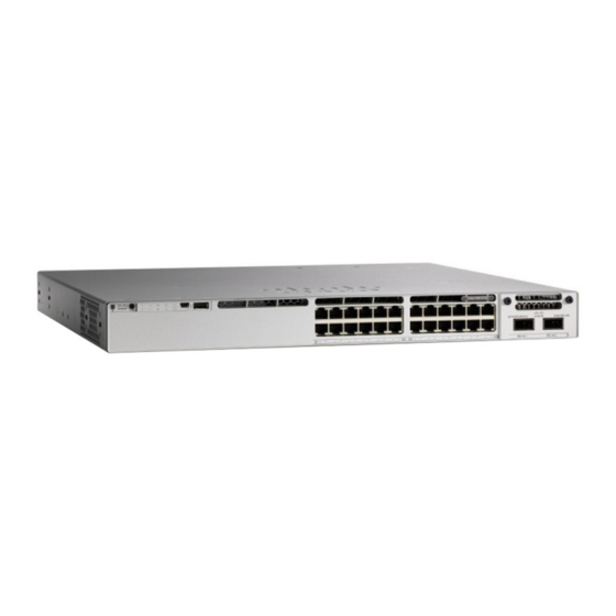
560 W with 1100 WAC power supply; supports StackWise-480 and StackPower. Front Panel Components This section describes the front panel components of a Cisco Catalyst 9300 Series switch: • 24 or 48 downlink ports of one of these types: ◦ 10/100/1000 ◦... -
Page 15: 10/100/1000 Ports
IEEE 802.3at-compliant powered devices (up to 30 W PoE+ per port). • Support for pre-standard Cisco powered devices. • Support Cisco UPOE powered devices (up to 60W PoE per port). The maximum total PoE power in a 1RU switch is 1800W. -
Page 16: Multigigabit Ports
Power Supply Modules, on page 14 for the power supply matrix that defines the available PoE, PoE+, and Cisco UPOE power per port. The output of the PoE+ or UPOE circuit has been evaluated as a Limited Power Source (LPS) per IEC 60950-1. -
Page 17: Usb Type A Port
The port supports Cisco USB flash drives with capacities from 128 MB to 8 GB (USB devices with port densities of 128 MB, 256 MB, 1 GB, 4 GB, and 8 GB are supported). When combined with stacking, you can upgrade other switches in the stack from an USB key inserted in any switch within the stack. -
Page 18: Leds
You can use the switch LEDs to monitor switch activity and its performance. Figure 4: Switch Front Panel LEDs USB Console LED The USB console LED shows whether there is an active USB connection to the port. Cisco Catalyst 9300 Series Switches Hardware Installation Guide... -
Page 19: System Led
Switch is the active switch or a standalone switch. Slow blinking green Switch is in stack standby mode. Amber An error occurred when the switch was selecting the active switch, or another type of stack error occurred. Cisco Catalyst 9300 Series Switches Hardware Installation Guide... -
Page 20: Stack Led
Stack member 3 LED is solid green to show that switch 3 is a stack member. PoE LED The PoE LED indicates the status of the PoE mode: either PoE, PoE+, or Cisco UPOE. Table 6: PoE LED Color Description PoE mode is not selected. -
Page 21: Xps Led
The power supply in a switch has failed, and the XPS is providing power to that switch (redundancy has been allocated to this device). For information about the XPS 2200, see the Cisco eXpandable Power System 2200 Hardware Installation Guide on Cisco.com: http://www.cisco.com/go/xps2200_hw... -
Page 22: Port Leds And Modes
Stack member status Stack member status. StackWise port status The StackWise port status. See STACK LED, on page The PoE+ port status. The PoE+ port status. 2 Only switches with PoE+ ports. Cisco Catalyst 9300 Series Switches Hardware Installation Guide... - Page 23 The switch is the active switch. Amber Error during active switch election. Blinking green Switch is a standby member of a data stack and assumes active responsibilities if the current active switch fails. Cisco Catalyst 9300 Series Switches Hardware Installation Guide...
-
Page 24: Beacon Led
The blue beacon on the front panel is a button labeled UID, and on the back panel it is a LED labeled BEACON. Color/State Description Solid blue The operator has indicated that the system needs attention. Cisco Catalyst 9300 Series Switches Hardware Installation Guide... -
Page 25: Network Module Leds
Caution Link faults occur when noncompliant cabling is connected to an SFP or SFP+ port. Use only standard-compliant cabling to connect to Cisco SFP and SFP+ ports. You must remove from the network any cable or device that causes a link fault. -
Page 26: Rj-45 Console Port Led
0.5-meter StackWise cable that you can use to connect the StackWise ports. For more information on StackWise cables, see Connecting to the StackWise Ports, on page Use only approved cables, and connect only to similar Cisco equipment. Equipment might be damaged Caution if connected to nonapproved Cisco cables or equipment. - Page 27 48-port full PoE+ switch PWR-C1-1100WAC 800 W 24-port Cisco UPOE switch 48-port Cisco UPOE switch Table 13: Switch Power Supply Requirements for PoE, PoE+, and Cisco UPoE PoE Option 24-Port Switch 48-Port Switch PoE (up to 15.4 W per port)
-
Page 28: Fan Module
ON. If the fan fails, the LED turns to amber. The switch can operate with two operational fans, but the failed fan should be replaced as soon as possible to avoid a service interruption due to a second fan fault. Cisco Catalyst 9300 Series Switches Hardware Installation Guide... -
Page 29: Stackpower Connector
Installing a Fan Module, on page StackPower Connector The switches have a StackPower connector for use with Cisco StackPower cables to configure a switch power stack that includes up to four switches. A switch power stack can be configured in redundant or power-sharing mode. -
Page 30: Rj-45 Console Port
See the switch software configuration guide for network configuration concepts and examples of using the switch to create dedicated network segments and interconnecting the segments through Fast Ethernet and Gigabit Ethernet connections. Cisco Catalyst 9300 Series Switches Hardware Installation Guide... -
Page 31: Switch Installation
This section includes the basic installation caution and warning statements. Read this section before you start the installation procedure. Translations of the warning statements appear in the Regulatory Compliance and Safety Information guide on Cisco.com. Cisco Catalyst 9300 Series Switches Hardware Installation Guide... - Page 32 This unit might have more than one power supply connection. All connections must be removed to Warning de-energize the unit. Statement 1028 Only trained and qualified personnel should be allowed to install, replace, or service this equipment. Warning Statement 1030 Cisco Catalyst 9300 Series Switches Hardware Installation Guide...
-
Page 33: Installation Guidelines
• Airflow around the switch and through the vents is unrestricted. • For copper connections on Ethernet ports, cable lengths from the switch to connected devices can be up to 328 feet (100 meters). Cisco Catalyst 9300 Series Switches Hardware Installation Guide... -
Page 34: Shipping Box Contents
Some components are optional, depending on your order. Note Verify that you have received these items. If any item is missing or damaged, contact your Cisco representative or reseller for instructions. Verify that you have received these items. If any item is missing or damaged, contact your Cisco representative or reseller for instructions. -
Page 35: Tools And Equipment
If a switch fails POST, the SYST LED turns amber. POST failures are usually fatal. Call Cisco technical support representative if your switch fails POST. After a successful POST, unplug the power cord from the switch and install the switch in a rack, on a wall, on a table, or on a shelf. -
Page 36: Planning A Switch Data Stack
If you do not specify the length of the StackWise cable, the 0.5-meter cable is supplied. If you need the 1-meter cable or the 3-meter cable, you can order it from your Cisco supplier. For cable part numbers, StackWise Ports, on page 14. -
Page 37: Data Stack Bandwidth And Partitioning Examples
The figures below show data stacks of switches with failover conditions. In this figure, the StackWise cable is bad in link 2. Therefore, this stack provides only half bandwidth and does not have redundant connections. Figure 13: Example of a Data Stack with a Failover Condition Cisco Catalyst 9300 Series Switches Hardware Installation Guide... -
Page 38: Power-On Sequence For Switch Stacks
◦ More than one stack cable is removed without powering down. • A stack split can occur in a partial ring stack if: ◦ A switch is removed without powering down. ◦ A stack cable is removed without powering down. Cisco Catalyst 9300 Series Switches Hardware Installation Guide... -
Page 39: Planning A Stackpower Stack
• Length of cable. Depending on the configurations that you have, you might need different-sized cables. If you do not specify the length of the StackPower cable, the 0.3 meter cable is supplied. If you need the 1.5 meter cable, you can order it from your Cisco supplier. For cable part numbers, see StackPower Connector, on page 17. -
Page 40: Stackpower Cabling Configurations
The cable is available in two lengths. Part Number Cable Type Length CAB-SPWR-30CM StackPower Cable 0.3 meter CAB-SPWR-150CM StackPower Cable 1.5 meter Figure 15: StackPower Cable for Use with Cisco Catalyst 9300 Series Switches Cisco Catalyst 9300 Series Switches Hardware Installation Guide... - Page 41 1.5-meter cable. In the examples that follow, the switches are stacked in a vertical rack or on a table. Figure 16: StackPower Ring Topology This figure shows nine switches connected in a star topology. Figure 17: StackPower Star Topology Cisco Catalyst 9300 Series Switches Hardware Installation Guide...
-
Page 42: Stackpower Partitioning Examples
Figure 19: Example of a Partitioned StackPower Stack with a Failover Condition Installing the Switch Rack-Mounting Installation in racks other than 19-inch racks requires a bracket kit not included with the switch. Cisco Catalyst 9300 Series Switches Hardware Installation Guide... - Page 43 Statement 1006 This figure shows the standard 19-inch brackets and other optional mounting brackets. You can order the optional brackets (ACC-KIT-T1=) from your Cisco sales representative. Figure 20: Rack-Mounting Brackets Cisco Catalyst 9300 Series Switches Hardware Installation Guide...
-
Page 44: Attaching The Rack-Mount Brackets
Use four Phillips flat-head screws to attach the long side of the bracket to each side of the switch for the front- or rear-mounting positions. Figure 21: Attaching Brackets for 19-inch Racks Cisco Catalyst 9300 Series Switches Hardware Installation Guide... -
Page 45: Mounting The Switch A Rack
Place the switch on the table or shelf near an AC power source. Step 4 When you complete the switch installation, see After Switch Installation, on page 34for information on switch configuration. Cisco Catalyst 9300 Series Switches Hardware Installation Guide... -
Page 46: After Switch Installation
Connecting to the StackWise Ports Before You Begin Before connecting the StackWise cables, review the Planning a Switch Data Stack, on page 24. Always use a Cisco-approved StackWise cable to connect the switches. Cisco Catalyst 9300 Series Switches Hardware Installation Guide... - Page 47 Connect the cable to the StackWise port on the switch rear panel. Align the connector and connect the StackWise cable to the StackWise port on the switch rear panel and finger-tighten the screws (clockwise direction). Make sure the Cisco logo is on the top side of the connector as shown in the figure. Step 3 Connect the other end of the cable to the port on the other switch and finger-tighten the screws.
-
Page 48: Connecting To The Stackpower Ports
Planning a Switch Data Stack, on page 24. Always use a Cisco-approved StackWise cable to connect the switches. To prevent misconfiguration, the StackPower ports on the switch are keyed and have colored bands that match the keying and bands on the StackPower cable connectors. -
Page 49: Connecting Devices To The Ethernet Ports
• 10/100/1000 Port Connections, on page 37 • PoE+ and Cisco UPOE Port Connections, on page 38 10/100/1000 Port Connections The switch 10/100/1000 port configuration changes to operate at the speed of the attached device. If the attached ports do not support autonegotiation, you can manually set the speed and duplex parameters. -
Page 50: Poe+ And Cisco Upoe Port Connections
PoE inline power supports devices compliant with the IEEE 802.3af standard, as well as prestandard Cisco IP Phones and Cisco Aironet Access Points. Each port can deliver up to 15.4 W of PoE. PoE+ inline power supports devices compliant with the IEEE 802.3at standard, by delivering up to 30 W of PoE+ power per port to all switch ports. -
Page 51: Chapter 3 Installing A Network Module
SFP and SFP+ Modules, page 49 • Finding the Network Module Serial Number, page 51 Network Modules Overview The Cisco Catalyst 9300 Series Switches supports the following optional network modules for uplink ports. Network Module Description C9300-NM-4G This module has four 1G SFP module slots. Any combination of standard SFP modules are supported. -
Page 52: Installing A Network Module In The Switch
Installing a Network Module in the Switch Safety Warnings This section includes the installation cautions and warnings. Translations of the safety warnings appear in the Regulatory Compliance and Safety Information for Cisco Catalyst 9300 Series Switches on Cisco.com: http:/ /www.cisco.com/go/c9300. -
Page 53: Installing Network Modules
Verify the correct orientation of your module before installing it. Incorrect installation can damage Caution the module. Do not install the network module with connected cables or installed SFP modules. Always remove Caution any cables and modules before you install the network module. Cisco Catalyst 9300 Series Switches Hardware Installation Guide... - Page 54 2 You will feel some light resistance, because a spring-loaded tab inside the slot will push back against the C3850-NM-8-10G module 3 Continue to tighten the jackscrew while gently pushing the front panel of the network module into the slot. Cisco Catalyst 9300 Series Switches Hardware Installation Guide...
-
Page 55: C9300-Nm-4G Module
TenGigabitEthernet1/1/8, even when you are operating them as 1 G using SFP. Table 19: C9300-NM-8-10X Module Interface Action TenGigabitEthernet1/1/1 Configure this interface TenGigabitEthernet1/1/2 Configure this interface TenGigabitEthernet1/1/3 Configure this interface TenGigabitEthernet1/1/4 Configure this interface TenGigabitEthernet1/1/5 Configure this interface TenGigabitEthernet1/1/6 Configure this interface Cisco Catalyst 9300 Series Switches Hardware Installation Guide... -
Page 56: C9300-Nm-2Q Module
GigabitEthernet1/1/4. There are only four interfaces that are valid, and the other four should not be used even though they still show up in the CLI. Table 21: C3850-NM-4-1G Module Interface Action GigabitEthernet1/1/1 Configure this interface Cisco Catalyst 9300 Series Switches Hardware Installation Guide... -
Page 57: C3850-Nm-4-10G Module
In the C3850-NM-2-10G module, the first two parts are natively 1-G ports and the last two ports are natively 10-G ports. So, you configure the 1-G posts as GigabitEthernet1/1/1 through GigabitEthernet1/1/2, and Cisco Catalyst 9300 Series Switches Hardware Installation Guide... -
Page 58: C3850-Nm-8-10G Module
TenGigabitEthernet1/1/1 Configure this interface TenGigabitEthernet1/1/2 Configure this interface TenGigabitEthernet1/1/3 Configure this interface TenGigabitEthernet1/1/4 Configure this interface TenGigabitEthernet1/1/5 Configure this interface TenGigabitEthernet1/1/6 Configure this interface TenGigabitEthernet1/1/7 Configure this interface TenGigabitEthernet1/1/8 Configure this interface Cisco Catalyst 9300 Series Switches Hardware Installation Guide... -
Page 59: C3850-Nm-2-40G Module
If you use a 4x10G breakout cable, the ports default to 10 G interfaces. Table 26: C3850-NM-2-40G Module with 4x10G breakout cable Interface Action FortyGigabitEthernet1/1/1 Disregard FortyGigabitEthernet1/1/2 Disregard TenGigabitEthernet1/1/1 Configure this interface TenGigabitEthernet1/1/2 Configure this interface TenGigabitEthernet1/1/3 Configure this interface Cisco Catalyst 9300 Series Switches Hardware Installation Guide... -
Page 60: Removing A Network Module
Grasp the captive screws, and carefully slide it out of the slot. Step 6 Install a replacement network module or a blank module in the slot. Step 7 Place the module that you removed in an antistatic bag or other protective environment. Cisco Catalyst 9300 Series Switches Hardware Installation Guide... -
Page 61: Sfp And Sfp+ Modules
You must have an installed network module to use SFP and SFP+ modules. See the switch release notes on Cisco.com for the list of supported SFP and SFP+ modules. Use only supported SFP modules on the switch. For the latest information about supported SFP and SFP+ modules, refer to the... - Page 62 If the module has a bale-clasp latch, close it to lock the SFP module in place. Step 6 Remove the SFP dust plugs and save. Step 7 Connect the SFP cables. Figure 26: Network Module with SFP Modules Installed Cisco Catalyst 9300 Series Switches Hardware Installation Guide...
-
Page 63: Removing Sfp And Sfp+ Modules
Place the SFP module in an antistatic bag or other protective environment. Finding the Network Module Serial Number If you contact Cisco Technical Assistance regarding a network module, you need to know its serial number. Figure 27: Network Module Serial Number Location... - Page 64 Installing a Network Module Finding the Network Module Serial Number Cisco Catalyst 9300 Series Switches Hardware Installation Guide...
-
Page 65: Chapter 4 Installing A Power Supply
The 350-W and 715-W AC power supply modules are autoranging units that support input voltages between 100 and 240 VAC. The 1100-W power supply module is an autoranging unit that supports input voltages between 115 and 240 VAC. Cisco Catalyst 9300 Series Switches Hardware Installation Guide... - Page 66 AC power cord connector Figure 29: 715-W AC Power Supply 715-W AC power supply module Release latch AC OK LED Power cord retainer PS OK LED Keying feature AC power cord connector Cisco Catalyst 9300 Series Switches Hardware Installation Guide...
- Page 67 Keying feature AC power cord connector If no power supply is installed in a power supply slot, install a power supply slot cover. Figure 31: Power Supply Slot Cover Release handles Retainer clips Cisco Catalyst 9300 Series Switches Hardware Installation Guide...
-
Page 68: Installation Guidelines
This equipment must be grounded. Never defeat the ground conductor or operate the equipment in the absence of a suitably installed ground conductor. Contact the appropriate electrical inspection authority or an electrician if you are uncertain that suitable grounding is available. Statement 1024 Cisco Catalyst 9300 Series Switches Hardware Installation Guide... -
Page 69: Installing Or Replacing An Ac Power Supply
Only trained and qualified personnel should be allowed to install, replace, or service this equipment. Warning Statement 1030 If a Cisco external power system is not connected to the switch, install the provided connector cover on Warning the back of the switch. - Page 70 Connect the power cord to the power supply and to an AC power outlet. Turn on the power at the power source. Step 8 Confirm that the power supply AC OK and PS OK LEDs are green. Cisco Catalyst 9300 Series Switches Hardware Installation Guide...
-
Page 71: Finding The Power Supply Module Serial Number
Finding the Power Supply Module Serial Number If you contact Cisco Technical Assistance regarding a power supply module, you need to know the serial number. See the following illustrations to find the serial number. You can also use the CLI to find out the serial number. - Page 72 Installing a Power Supply Finding the Power Supply Module Serial Number Cisco Catalyst 9300 Series Switches Hardware Installation Guide...
-
Page 73: Chapter 5 Installing A Fan Module
The switch can operate with two operational fans and one nonfunctional fan, but the failed fan should be replaced as soon as possible to avoid a service interruption due to a second fan fault. Figure 36: Fan Module Fan LED Retainer clip Cisco Catalyst 9300 Series Switches Hardware Installation Guide... -
Page 74: Installation Guidelines
When correctly inserted, the fan module is flush with the switch rear panel. When the fan is operating, a green LED is on in the top left corner of the fan. Cisco Catalyst 9300 Series Switches Hardware Installation Guide... -
Page 75: Finding The Fan Module Serial Number
Finding the Fan Module Serial Number If you contact Cisco Technical Assistance regarding a fan module, you need to know the fan module serial number. See the following illustration to find the serial number. Figure 38: Fan Module Serial Number... - Page 76 Installing a Fan Module Finding the Fan Module Serial Number Cisco Catalyst 9300 Series Switches Hardware Installation Guide...
-
Page 77: Configuring The Switch
Set a password of up to 25 alphanumeric characters. The username password combination you set gives you privilege 15 access. The string cannot start with a number, is case sensitive, and allows spaces but ignores leading spaces. Cisco Catalyst 9300 Series Switches Hardware Installation Guide... -
Page 78: Choosing Setup Options
To ease your configuration tasks and save time, choose a site profile based on where your device may be installed and managed in your network. Based on the site profile you choose, your device is automatically configured according to Cisco best practices. You can easily modify this default configuration, from the corresponding detailed configuration screens. - Page 79 Version 2 Version 2 Version 2 Version 2 Enabled Enabled Enabled Enabled Enabled Enabled VTY Access Enabled Enabled Enabled Enabled Enabled Enabled to Switch Service Enabled Enabled Enabled Enabled Enabled Enabled Timestamp Cisco Catalyst 9300 Series Switches Hardware Installation Guide...
- Page 80 VLANs VLANs. VLANs. Cisco Catalyst 9300 Series Switches Hardware Installation Guide...
-
Page 81: Configuring Switch Wide Settings
PVRST+ is the default STP mode configured on your device. You can change it to PVST from the STP Mode drop-down list. Step 2 To change a bridge priority number from the default value 32748, change Bridge Priority to Yes and choose a priority number from the drop-down list. Cisco Catalyst 9300 Series Switches Hardware Installation Guide... -
Page 82: Configure Dhcp, Ntp, Dns And Snmp Settings
If you have stacked your switches, connect to the console port of one of the switches in the stack. You Note can initially configure the entire stack from any member switch. Cisco Catalyst 9300 Series Switches Hardware Installation Guide... -
Page 83: Connecting The Rj-45 Console Port
If you are connecting the switch USB console port to a Windows-based PC for the first time, install the USB driver. See Installing the Cisco Microsoft Windows USB Device Driver, on page USB Type A port on the switch provides file system support and is NOT a console port. See USB Note Type A Port section. -
Page 84: Installing The Cisco Microsoft Windows Usb Device Driver
Installing the Cisco Microsoft Windows XP USB Driver Procedure Step 1 Obtain the Cisco USB console driver file from the Cisco.com web site and unzip it. Note You can download the driver file from the Cisco.com site for downloading the switch software. -
Page 85: Installing The Cisco Microsoft Windows Vista And Windows 7 Usb Driver
Installing the Cisco Microsoft Windows Vista and Windows 7 USB Driver Procedure Step 1 Obtain the Cisco USB console driver file from the Cisco.com web site and unzip it. Note You can download the driver file from the Cisco.com site for downloading the switch software. -
Page 86: Using The Add Or Remove Programs Utility
Scroll to Cisco Virtual Com and click Remove. Step 3 When the Program Maintenance window appears, select the Remove radio button. Click Next. Uninstalling the Cisco Microsoft Windows Vista and Windows 7 USB Driver Before You Begin Disconnect the switch console terminal before uninstalling the driver. -
Page 87: Appendix A Technical Specifications
This table describes the environmental specifications. Table 31: Environmental Specifications for the Power Supplies Environmental Ranges Operating temperature AC power supply: 23 to 113°F (–5 to 45°C) Storage temperature –40 to 158°F (–40 to 70°C) Cisco Catalyst 9300 Series Switches Hardware Installation Guide... - Page 88 17.03 lb (7.72 kg) C9300-24UX 18.18 lb (8.25 kg) This table describes the physical specifications. Table 33: Physical Specifications for the Power Supplies Weight PWR-C1-1100WAC 3 lb (1.4 kg) PWR-C1-715WAC 2.8 lb (1.3 kg) Cisco Catalyst 9300 Series Switches Hardware Installation Guide...
-
Page 89: Specifications For The Power Supplies, Switches, And Fan
• PWR-C1-350WAC: 350 W, 100 to 240 VAC(autoranging) 50-60 Input current • PWR-C1-1100WAC: 12–6 A • PWR-C1-715WAC: 10–5 A • PWR-C1-350WAC: 4–2 A Output ratings • PWR-C1-1100WAC: –56 [email protected] A • PWR-C1-715WAC: –56 [email protected] A • PWR-C1-350WAC: –56 [email protected] A Cisco Catalyst 9300 Series Switches Hardware Installation Guide... - Page 90 Physical Specification Dimensions (H x D x W) 1.62 x 1.73 x 4.24 in. (4.11 x 4.39 x 10.76 cm) Weight (for three fans) 0.48 lb (0.21 kg) Operating Specification Airflow 20 cfm Cisco Catalyst 9300 Series Switches Hardware Installation Guide...
-
Page 91: Appendix B Connector And Cable Specifications
• Console Port, page 81 • Cables and Adapters, page 81 Connector Specifications 10/100/1000 Ports (Including PoE) All 10/100/1000 ports use standard RJ-45 connectors and Ethernet pinouts. Figure 39: 10/100/1000 Port Pinouts Cisco Catalyst 9300 Series Switches Hardware Installation Guide... -
Page 92: Sfp Module Connectors
Connector and Cable Specifications SFP Module Connectors SFP Module Connectors Figure 40: Duplex LC Cable Connector Figure 41: Simplex LC Cable Connector Figure 42: Copper SFP Module LC Connector Cisco Catalyst 9300 Series Switches Hardware Installation Guide... -
Page 93: Console Port
Cables and Adapters StackWise Cables You can order these StackWise cables (nonhalogen) from your Cisco sales representative: • STACK-T1-50CM= (0.5-meter cable) • STACK-T1-1M= (1-meter cable) • STACK-T1-3M= (3-meter cable) -
Page 94: Sfp Module Cables
• Cisco 40-Gigabit QSFP+ Transceiver Modules Installation Note Cisco Catalyst 2960-X and 2960-XR Switches now support QSFP-4X10G-AOC5M, the 40GQSFP to four 10G SFP+ direct attach breakout Active Optical cable assembly. Each port must match the wave-length specifications on the other end of the cable, and the cable must not exceed the stipulated cable length. -
Page 95: Cable Pinouts
Cable Pinouts Cable Pinouts Figure 45: Four Twisted-Pair Straight-Through Cable Schematic Figure 46: Four Twisted-Pair Semi-Cross Cable Schematic Figure 47: Two Twisted-Pair Straight-Through Cable Schematic Figure 48: Two Twisted-Pair Crossover Cable Schematic Cisco Catalyst 9300 Series Switches Hardware Installation Guide... -
Page 96: Console Port Adapter Pinouts
PC. You need to provide a RJ-45-to-DB-25 female DTE adapter to connect the switch console port to a terminal. Table 36: Console Port Signaling with a DB-9 Adapter Switch Console Port (DTE) RJ-45-to-DB-9 Terminal Adapter Console Device Signal DB-9 Pin Signal Cisco Catalyst 9300 Series Switches Hardware Installation Guide... - Page 97 Switch Console Port (DTE) RJ-45-to-DB-9 Terminal Adapter Console Device Signal DB-9 Pin Signal Table 37: Console Port Signaling with a DB-25 Adapter Switch Console Port (DTE) RJ-45-to-DB-25 Terminal Adapter Console Device Signal DB-25 Pin Signal Cisco Catalyst 9300 Series Switches Hardware Installation Guide...
- Page 98 Connector and Cable Specifications Console Port Adapter Pinouts Cisco Catalyst 9300 Series Switches Hardware Installation Guide...