
Related Manuals for JVC TK-C675BU


Summary of Contents for JVC TK-C675BU
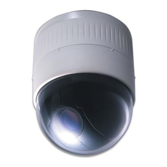
- Page 1 SERVICE MANUAL COMBINATION CAMERA TK-C675BU/TK-C675BE No. 6681 December 1998 COPYRIGHT © 1998 VICTOR COMPANY OF JAPAN, LTD.
-
Page 2: Table Of Contents
TABLE OF CONTENTS Section Title Page Section Title Page INSTRUCTIONS 1. DISASSEMBLY 3. DIAGRAMS AND CIRCUIT BOARDS 1.1 REMOVING THE SIDE AND DOME COVERS .... 1-1 3.1 CCD/PR BOARD BLOCK DIAGRAMS ......3-2 1.2 REMOVING THE CAMERA ......... 1-1 3.2 IF BOARD BLOCK DIAGRAM ........3-3 1.3 REPLACING THE CCD IMAGE SENSOR .... -
Page 3: Disassembly
SECTION 1 DISASSEMBLY 1.1 REMOVING THE SIDE AND DOME COVERS 1.2 REMOVING THE CAMERA (1) Rotate the side cover A in the direction of and remove (1) Remove the covers as described in 1.1. it from the main body. (2) Unplug the FPC cable C from the IF board. IF board Fig. -
Page 4: Replacing The Ccd Image Sensor
1.3 REPLACING THE CCD IMAGE SENSOR (3) Lightly push the section of the right camera cover F . (4) Remove the left camera cover E in the direction as indi- The image sensor is interchangeable only with a specified cated by the arrow →. image sensor. -
Page 5: Removing Major Circuit Boards
1.4 REMOVING MAJOR CIRCUIT BOARDS 1.4.3 Removing the MD board and MD SUB board (1) Remove the camera as described in 1.2. 1.4.1 Removing the PR board (2) Remove the IF board as described in 1.4.2. (1) Remove the camera cover as described in 1.3. (3) Remove the blind mask L . -
Page 6: Removing The Cn Board
1.4.5 Removing the power supply unit (6) Remove the 2 spacers R . (7) Remove the MD. INSULATOR Q and remove the MD SUB (1) Remove the screws and disconnect the connectors as de- board. scribed in 1.4.4. (2) Remove the 2 screws 12 . Fig. -
Page 7: Removing The Lens Assembly
The settings of other DIP switches than S1 on the CN board. board and S1-6 on the MD board are read at the time ON : Uses the JVC-CAM protocol. the power is turned ON. Therefore, when changing the position of these DIP switches, it is necessary to turn S3-4 Not used. -
Page 8: Consumable Parts
1.6 CONSUMABLE PARTS 1.8 Replacement of IC ROM (IF board IC27, IC29) The pan/tilt assembly and the lens assembly of the TK-C675B (1) For removing the IC ROM, it is recommended to use a spe- are consumable parts. Therefore, their servicing is charged to cial tool, however, two small screwdrivers are substitutable the user even when it occurs within the warranty period. -
Page 9: Positional Adjustments To The Sensor Plate
1.9 Positional adjustments to the sensor plate 1.10 Care in Transportation Whenever the sensor plate has been replaced, carry out the In order to prevent damage to the photo interrupter on the IF adjustments listed below. board during transportation, a bracket has been added. Be sure to remove the bracket before installation by referring to the dia- (1) Loosen screw 1 . -
Page 10: Electrical Adjustments
Color temp. Conversion filter Lens mount tool Focus chart Camera Stand KODAK wratten gelatin filter YTU93072 No. 80C (or equivalent) SC32125 (Included in Infirity adjustment lens.) YTU93079 * When used with TK-C675BU/E, it does not display “Camera Model” and “Camera ID”. -
Page 11: General Setup
2.3 GENERAL SETUP Connect the equipment as shown below. The Left camera cover should be removed for adjustments (see 1.1). Lens mount tool SC32125 POWER SUPPLY DC 6V Adjustment IF board software TK-C675B Infinity adjustment lens YTU92001B Light box YTU93072 Conversion cable To RS422 SC32124... -
Page 12: How To Execute Program Software (Plsc1209)
2.5 HOW TO EXECUTE PROGRAM SOFTWARE (PLSC1209) 2.6 KEYBOARD OPERATION (PLSC1209) 1) Install the MS-DOS “MOUSE. COM”. (This program can also Although a mouse is recommended for using this program, it be used without Mouse.) can also be operated from the keyboard in cases when a mouse 2) At the MS-DOS command line, type as follows. -
Page 13: Camera Adjustment
2) BUFF menu 2.8 CAMERA ADJUSTMENT • Light source and object for adjustment Menu command Function Use the specified light box and object when adjusting the camera with this program. Buffer 1 Display white balance data on • Adjustment Buffer 2 main window. -
Page 14: Evr Adjustment
Measuring point ( Measuring Adjustment parts ( Item instrument & Mode Adjustment procedure Adjustment level ( Input signals 2.10 EVR ADJUSTMENT • After replacing the CCD image sensor or EEPROM, execute “Restore” in the EEPROM menu to write the initial value data “TKC675_N.DAT”(U Ver.) or “TKC675_P.DAT”(E Ver.) in EEPROM before proceeding to the adjustment. - Page 15 Measuring point ( Measuring Adjustment parts ( Item instrument & Mode Adjustment procedure Adjustment level ( Input signals Y setup • Oscilloscope VIDEO output 1) Close the lens iris. adjustment (H-rate, 10:1) 22h (Y setup level) 2) Adjust the Y set up level data so that setup 30mVp-p level is 30mVp-p.
- Page 16 Measuring point ( Measuring Adjustment parts ( instrument & Item Mode Adjustment procedure Adjustment level ( Input signals Burst level • Oscilloscope VIDEO output 1) Adjust the Burst level data so that the level adjustment (H-rate, 10:1) 25h (Burst level) of the burst signal at the VIDEO output is •...
- Page 17 Measuring point ( Measuring Adjustment parts ( Item instrument & Mode Adjustment procedure Adjustment level ( Input signals Color • Color bar chart VIDEO output 1) Set lens iris so that the white level of the color difference (just scan) LENS IRIS bar chart is 0.65Vp-p.
- Page 18 Measuring point ( Measuring Adjustment parts ( Item instrument & Mode Adjustment procedure Adjustment level ( Input signals SC phase • Color bar chart VIDEO output 1) Attach the infinity adjustment lens with color adjustment (just scan) LENS IRIS bar chart to the lens. (E Ver.
- Page 19 Measuring point ( Measuring Adjustment parts ( Item instrument & Mode Adjustment procedure Adjustment level ( Input signals R, B gain (INDOOR) VIDEO output 1) Set lens iris so that white level of color bar (indoor/ • Color bar chart LENS IRIS chart is 0.65Vp-p at VIDEO output.
- Page 20 Measuring point ( Measuring Adjustment parts ( instrument & Item Mode Adjustment procedure Adjustment level ( Input signals Color differ- (INDOOR) VIDEO output 1) Set lens iris so that the white level of color ence gain • Color bar chart LENS IRIS bar chart is 0.65Vp-p at VIDEO output.
- Page 21 Measuring point ( Measuring Adjustment parts ( instrument & Item Mode Adjustment procedure Adjustment level ( Input signals Color differ- (INDOOR) VIDEO output 1) Adjust lens iris so that white level of color bar ence matrix • Color bar chart LENS IRIS chart is 0.65Vp-p at VIDEO output.
- Page 22 Measuring point ( Measuring Adjustment parts ( Item instrument & Mode Adjustment procedure Adjustment level ( Input signals Manual • Gray scale chart W.BAL is set VIDEO output 1) Attach the infinity adjustment lens with gray WHT. BAL (just scan) automatically LENS IRIS scale chart to the lens.
- Page 23 Measuring point ( Measuring Adjustment parts ( Item instrument & Mode Adjustment procedure Adjustment level ( Input signals Auto iris level • Gray scale chart LENS IRIS: VIDEO output 1) Set the iris to “AUTO”. adjustment (just scan) AUTO 35h (Auto iris level) 2) Adjustment the Auto Iris level data so that •...
- Page 24 VICTOR COMPANY OF JAPAN, LIMITED Printed in Japan...
- Page 26 RISK OF ELECTRIC SHOCK DO NOT OPEN...
- Page 27 TX– VIDEO OUT RX– and more than and more than and more than and more than RX+ RX– (TX+) (TX–) (RX+) (RX–) TX+ TX–...
- Page 28 RX TERM (110 Ω) SC46125-002...
- Page 30 Screw positions...
-
Page 31: Diagrams And Circuit Boards
SECTION 3 DIAGRAMS AND CIRCUIT BOARDS SCHEMATIC DIAGRAM NOTES REPLACING SUBMINIATURE “CHIP” PARTS ● Schematic safety precaution • Some resistors, shorting jumpers (0 Ω resistance), ceramic ! Parts are safety related parts. capacitors, transistors, and diodes are chip parts. These chip When replacing them, be sure to use the specified parts. -
Page 32: Ccd/Pr Board Block Diagrams
CCD/PR BOARD BLOCK DIAGRAMS... -
Page 33: If Board Block Diagram
IF BOARD BLOCK DIAGRAM... -
Page 34: Ccd Board Schematic Diagram
CCD BOARD SCHEMATIC DIAGRAM FROM/TO PR CN201 15.3 4.5 4.4 4.5 -5.0 -8.2 -10.0 -10.0 -10.0 10.0 -7.5 15.3 -10.0 -10.0 -6.1 -5.7 -5.8 -5.7 -7.5 10.0 -5.8 0.6 15.3 15.5 15.3 15.5 15.5 0.2 0 9.5 4.6 -4.6 15.3 ... -
Page 35: Pr Circuit Board
PR CIRCUIT BOARD side A side B ADDRESS TABEL OF BOARD PARTS Each address may have an address error by one interval. A-1C B-2A A-2D B-4B A-3D A-3D R154 B-1A R215 B-2C R246 A-1C R277 B-3C R354 B-3C R403 B-3D... -
Page 36: Pr Board Schematic Diagram
PR BOARD SCHEMATIC DIAGRAM The components shown in are not actually mounted on the board. U : NAX0078-001X E : NAX0051-001X OPEN CCD V TRANSFER CCD H DRIVE PLUSE GEN. PLUSE GEN. 8fsc FROM/TO CCD CN101 U : 0 H-rate V-rate GATE ... -
Page 37: If Board Schematic Diagram
IF BOARD SCHEMATIC DIAGRAM The components shown in are not actually mounted on the board. SCV2732-1LL241 FROM/TO PR CN202 FROM/TO MD CN10 A3-J OPEN A3-J OPEN 390k 820k 0.027 15.0 FROM/TO SLIP RING PAN MSTEP1 PAN MSTEP0 PLSC1247 OPEN OPEN OPEN OPEN... -
Page 38: If Board Circuit Board
IF BOARD CIRCUIT BOARD side A side B ADDRESS TABEL OF BOARD PARTS B-1A IC32 B-2E B-2A A-2A B-1B A-4C B-1D R116 B-5B R141 B-3A R168 B-1C R214 B-3E B-1B B-1C B-5A C110 B-2A L200 B-2A A-3B Each ... -
Page 39: Md/Md Sub Board Schematic Diagram
MD/MD SUB BOARD SCHEMATIC DIAGRAM The components shown in are not actually mounted on the board. FROM/TO IF CN10 12.0 FROM/TO PAN MOTOR 15.1 13.2 15.1 13.2 12.0 13.3 FROM/TO MD SUB CN504 15.1 11.9 12.9 11.9 12.9 S1-1 RESERVED S1-2 RESERVED... -
Page 40: Md Board Circuit Board
3.10 MD BOARD CIRCUIT BOARD side A side B ADDRESS TABEL OF BOARD PARTS 3.11 MD SUB CIRCUIT BOARD Each address may have an address error by one interval. A-1C side B Side Y axis X axis B-4B B-3C B-4B... -
Page 41: Cn Board Schematic Diagram
3.12 CN BOARD SCHEMATIC DIAGRAM 3.14 TM BOARD SCHEMATIC DIAGRAM FROM/TO CN CN3 FROM/TO PS UNIT CN2 FROM/TO TN CN3 11.9 93451 15.2 3.15 TM CIRCUIT BOARD side B FROM/TO SLIP RING FROM/TO PS UNIT CN1 93450 3.13 CN CIRCUIT BOARD ... -
Page 42: Overall Wirings
3.16 OVERALL WIRINGS FFC CABLE 92586 3-12 3-12... -
Page 43: Block Diagrams Of Ic's
3.17 BLOCK DIAGRAMS of IC’s AN2018S-W [MATSUSHITA] AN2147FHP [MATSUSHITA] (Correlated Double Sampling) (Signal Processer) AN2458SH-E1 [MATSUSHITA] (Color Encoder) 3-13 3-13... - Page 44 AN7705F [MATSUSHITA] CY62256LL70SN-X [CYPRESS] EHDGA1534 [MATSUSHITA] (3-Terminal Voltage Regulator) (32k x 8 Static RAM) (SC Generator for PAL) BA10324AFV-X [ROHM] EHDGA1533 [MATSUSHITA] (Quad Ground Sense Operational Amplifiers) (SC Generator for NTSC) CXA1211M-X [SONY] (Electric Volume) MAX489CPD [MAXIM] (Low-Power,Slew-Rate-Limited RS-485/RS-422 Transceivers) 3-14 3-14...
- Page 45 M28C64-120K1 [MITSUBISHI] MB88345PF [FUJITSU] MB90T678BPF [MITSUBISHI] (Parallel 64K(8K X 8)EEPROM with Software Data (D/A Converter) (CPU) Protection) 3-15 3-15...
- Page 46 PLSC1247 [FUJITSU] MC14046BF-X [MOTOROLA] MC74AC373M-X [MOTOROLA] MC74HC04AF-X [MOTOROLA] (2M Bit Flash Memory) (Phase Locked Loop) (Octal Transparent Latch with 3-State Output) (Hex Inverters) MN3864SA-W [MATSUSHITA] (CCD Delay Line) MC74HC14AF-X [MOTOROLA] MC74HC367F-X [MOTOROLA] MN12821-QR-X [MATSUSHITA] (Hex Schmitt-Trigger Inverters) (Hex Bus Drivers With 3-State NON-In- (Voltage Detecter) verted Output) 3-16...
- Page 47 MN3111H [MATSUSHITA] NJM2267V-W [JRC] MN5216-2 [MATSUSHITA] (Vertical Driver) (Dual 6dB Video Amplifier including (Timing Generator) 75Ω Driver) NJM2509V-W [JRC] (Super Imposer including Y/C MIX Circuit) 3-17 3-17...
- Page 48 3-18 3-18...
- Page 49 3-19 3-19...
- Page 50 3-20 3-20...
- Page 51 NJM2904M-X [JRC] NM93C46EM8-X [NATIONAL SEMICON- P22V10D-15-002 [CYPRESS SEMICON- (Dual Op.Amp.) DUCTOR] DUCTOR] (1024-Bit Serial EEPROM) (Programmable Logic Array) NJM319D [JRC] (Voltage Comparator) S-8054HN-CB-X [SEIKO INSTRUMENTS] SMA5104 [SANKEN] (Power MOS FET Array) (C-MOS Voltage Detector) S-2927AIF10G-W [SEIKO] (CMOS 2K-bit Serial EE PROM) 3-10 3-21 3-10...
- Page 52 SSS3M-001 [JAPAN SERVO] TC4W53F-X [TOSHIBA] TC74HC32AF-X [TOSHIBA] (µ-Step Driver for Three Phase Stepping Motor) (2-Channel Multiplexer) (Quad 2-Input OR Gates) TC74HC4053AFT-X [TOSHIBA] (Triple 2-Channel Analog Multiplexer/ Demultiplexer) TA75S01F-W [TOSHIBA] TA75W558FU-X [TOSHIBA] (Single Op.Amp.) (Dual Low-Noise Op.Amp.) TC7S04F-X [TOSHIBA] (Invertor) 3-11 3-22 3-11 3-22...
- Page 53 TC74VHC153F-X [TOSHIBA] TK11650U-X [TOKO] (Dual 4-Channel Multiplexer) (3-Terminal Positive Voltage Regulator) TC7W00FU-X [TOSHIBA] TC7W08F-X [TOSHIBA] UPC842G2-W [NEC] UPD6461GS-936 [NEC] (2 Input Dual NAND Gate) (2 Input Dual AND Gate) (Dual Op.Amp.) (On Screen Charactor Display) TC7W04F-X [TOSHIBA] (Triple Inverter Gate) 3-12 3-23 3-12...
- Page 54 PLSC1183 [NEC] (8 Bit Single Chip Microcomputer with 32k Byte One Time P-ROM) Z84C4310FEC [ZILOG] (Serial I/O Controller) 3-13 3-24 3-13 3-24...
-
Page 55: Exploded View And Parts List
SECTION 4 EXPLODED VIEW AND PARTS LIST 4.1 EXPLODED VIEW M 1 SAFETY PRECAUTIONS: Parts identified by the ! symbol are critical for safety. Replace only with specified parts number. For maximum reliability and performance, all other replacement parts should be identical to those specified. - Page 56 4.1 ASSEMBLY PARTS LIST M 1 M 1 M M ` ` ` ` Symbol Part No. Part Name Description 1 SCV2843-00B LENS ASSEMBLY 2 SC32104-002 SENSOR BASE 3 QAJ0004-001 OP L.P.F 4 SC45648-002 SENSOR MASK 5 MN3718MFE for U Ver. 5 MN3728MFE for E Ver.
- Page 57 SECTION 6 PACKING Instructions Carton SC96837 Carton Carton Ceiling mount assembly Camera CLAMP FILTER Caution sheet SCV2728-001 SC96820-001 Carton Carton Box Carton CLAMP FILTER QQR0216-001...
-
Page 58: Electrical Parts List
Parts identified by the ! symbol are criticaI for safety. Replace only with specified parts numbers. For maximum reliability and performance, all other replacement parts should be identical to those specified. NOTE: ● Parts not denoted by parts numbers are not supplied by JVC. ● Abbreviations in this list are as follows: RESISTORS CAPACITORS In the “Description”... -
Page 59: Ccd Board Assembly Parts List
5.1 CCD BOARD ASSEMBLY PARTS LIST 0 1 ` ` ` ` ` ` SCK2496-01-A0A Symbol Symbol Part No. Part Name Description Part No. Part Name Description TK11650U-X I.C.(M) TOKO DENSHI C118 NBE61VM-156X TAN.CAPACITOR C119 NCF31EZ-104X CER.CAPACITOR SK101 SCV2648-001 IC SOCKET for CCD C120 NCF31EZ-104X... -
Page 60: Pr Board Assembly Parts List
5.2 PR BOARD ASSEMBLY PARTS LIST SCK2496-02-N1A(U) 0 2 ` ` ` ` ` ` SCK2496-02-P1A(E) Symbol Symbol Part No. Part Name Description Part No. Part Name Description TC74VHC153F-X I.C.(M) TOSHIBA NRSA63J-102X M.G.RESISTOR 1/16W TC7W04F-X I.C.(M) TOSHIBA NRSA63J-102X M.G.RESISTOR 1/16W TK11650U-X I.C.(M) TOKO DENSHI... - Page 61 Symbol Symbol Part No. Part Name Description Part No. Part Name Description R202 NRSA63J-472X M.G.RESISTOR 4.7k 1/16W R285 NRSA63J-0R0X M.G.RESISTOR 1/16W (U) R203 NRSA63J-472X M.G.RESISTOR 4.7k 1/16W NRSA63J-203X M.G.RESISTOR 1/16W (E) R204 NRSA63J-472X M.G.RESISTOR 4.7k 1/16W R286 NRSA63J-103X M.G.RESISTOR 1/16W R205 NRSA63J-332X M.G.RESISTOR...
- Page 62 [PR] Symbol Symbol Part No. Part Name Description Part No. Part Name Description NBE21AM-335X TAN.CAPACITOR C239 NDC31HJ-180X CER.CAPACITOR C240 NCF31HZ-473X CER.CAPACITOR 0.047 NCF31EZ-104X CER.CAPACITOR C241 NCF31EZ-104X CER.CAPACITOR NCF31EZ-104X CER.CAPACITOR C242 NCB31HK-103X CER.CAPACITOR 0.01 NCF31EZ-104X CER.CAPACITOR C243 NCF31EZ-104X CER.CAPACITOR NCF31EZ-104X CER.CAPACITOR C244 NBE21AM-106X TAN.CAPACITOR...
-
Page 63: If Board Assembly Parts List
5.3 IF BOARD ASSEMBLY PARTS LIST SCK2496-03-N1A(U) 0 3 ` ` ` ` ` ` SCK2496-03-P1A(E) Symbol Symbol Part No. Part Name Description Part No. Part Name Description X101 NAX0078-001X CRYSTAL 8fsc MC14046BF-X I.C.(M) MOTOROLA NAX0051-001X CRYSTAL 8fsc NJM2904M-X I.C.(M) X201 PEVB0572-Z CRYSTAL... - Page 64 [IF] Symbol Symbol Part No. Part Name Description Part No. Part Name Description NRSA63J-103X M.G.RESISTOR 1/16W R170 NRSA63J-220X M.G.RESISTOR 1/16W NRSA63J-103X M.G.RESISTOR 1/16W R171 NRSA63J-220X M.G.RESISTOR 1/16W NRSA63J-103X M.G.RESISTOR 1/16W NRSA63J-103X M.G.RESISTOR 1/16W R172 NRSA63J-0R0X M.G.RESISTOR 1/16W NRSA63J-103X M.G.RESISTOR 1/16W R173 NRSA63J-0R0X M.G.RESISTOR...
-
Page 65: Md Board Assembly Parts List
5.4 MD BOARD ASSEMBLY PARTS LIST 0 4 ` ` ` ` ` ` SCK2497-01-B0B Symbol Symbol Part No. Part Name Description Part No. Part Name Description NCF31EZ-104X CER.CAPACITOR AN7705F I.C.(M) MATSUSHITA NCF31EZ-104X CER.CAPACITOR SMA5104 I.C.(M) SANKEN C100 NEH91EM-336X E.CAPACITOR SMA5104 I.C.(M) SANKEN... -
Page 66: Md Sub Board Assembly Parts List
5.6 CN BOARD ASSEMBLY PARTS LIST 0 6 ` ` ` ` ` ` SCK2497-02-B0B [MD] Symbol Symbol Part No. Part Name Description Part No. Part Name Description NCF21EZ-104X CER.CAPACITOR NJM319D I.C.(M) QTMC1HM-106Z E.CAPACITOR MAX489CPD I.C.(M) MAXIM NCF21EZ-104X CER.CAPACITOR TK11650U-X I.C.(M) TOKO DENSHI QTMC1EM-107Z...