YASKAWA DX200 User Manual
Robot
Show thumbs
Also See for DX200:
- Maintenance manual (1166 pages) ,
- Instructions manual (552 pages) ,
- Operator's manual (120 pages)
1
2
Table Of Contents
3
4
5
6
7
8
9
10
11
12
13
14
15
16
17
18
19
20
21
22
23
24
25
26
27
28
29
30
31
32
33
34
35
36
37
38
39
40
41
42
43
44
45
46
47
48
49
50
51
52
53
54
55
56
57
58
59
60
61
62
63
64
65
66
67
68
69
70
71
72
73
74
75
76
77
78
79
80
81
82
83
84
85
86
87
88
89
90
91
92
93
94
95
96
97
98
99
100
101
102
103
104
105
106
107
108
109
110
111
112
113
114
115
116
Table of Contents
Table of Contents

Related Manuals for YASKAWA DX200


Summary of Contents for YASKAWA DX200
- Page 1 ROBOTICS Installation and Wiring Robot controller User manual...
- Page 2 This documentation – also in part – may be reproduced or made available to third parties only with the express approval of YASKAWA Europe "Robotics Division GmbH". We have checked the content of this publication for compliance with the hardware described.
-
Page 3: Table Of Contents
YASKAWA manual list ........ - Page 4 Table of contents Maintenance and inspection ..........44 Periodic inspection .
- Page 5 Table of contents 8.29.6 The list of the Equipment configuration by model..... . . 105 Robot controller specification ..........108 Specification list .
-
Page 6: General
This signal word can also be used for property damage warnings. Frequently used terms The YASKAWA robot is a product of YASKAWA Electric Corporation, and is provided by default with the robot control, the programming pendant and robot cable. -
Page 7: Target Group
For optimal use of our products, we recommend our customers to take part in a training session at the YASKAWA Academy. For more detailed information on the training programme, please visit www.yaskawa.eu.com or directly get in touch with your YASKAWA branch office. -
Page 8: Improper Use
General Improper use Any use that deviates from the intended use shall be regarded as impermissible misuse. This includes: • Transport of people and animals • Use as ascending aid. • Use outside the permissible operating limits. • Use in environments with risk of explosion (except for ATEX-approved robots). •... -
Page 9: About This Manual
If your copy of the operating and maintenance instructions is damaged or lost, please contact the local YASKAWA branch office to order a new copy. The official branch offices are listed on the last page. Please mention the manual number in your order. -
Page 10: Safety
General Description of the operation procedure In the explanation of the operation procedure, the expression "Select", • means that the cursor is moved to the object item and the [SELECT] key is pressed. • that the item is directly selected by touching the screen. Registered Trademark The names of companies and/or products used in this manual are trademarks. - Page 11 General WARNING! Death or injury because of danger of crushing Before you release the emergency stop button (see Fig. 1-4: "Release of emergency stop button by turning") note the following: Make sure that there is no one within the maximum working range of the robot. ...
-
Page 12: For Your Security
For optimal use of our products, we recommend our customers to take part in a training session at the YASKAWA Academy. For more detailed information on the training programme, please visit www.yaskawa.eu.com or directly get in touch with your YASKAWA... -
Page 13: Yaskawa Manual List
1.7.2 YASKAWA manual list It is important to have all the manuals on the YASKAWA control or robot available and to know their contents. Please make sure you have all these manuals. If you are missing any manual, please contact the local YASKAWA branch office. - Page 14 General CAUTION! Injury and material damage due to unforeseen movements. Observe the following note: • Never forcibly move the robot axes. • Never lean against the robot control. • Avoid inadvertent pressing of the keys. • Do not allow unauthorised persons to touch the robot control during operation. Fig.
-
Page 15: Safety During Installation And Wiring
General 1.7.4 Safety during installation and wiring For further details of the installation and the electrical connection please see Chapter 5.3.2 "Connection of the robot controller" on page 38. DANGER due to electric current! Death and serious injury from electrical shock and fire hazard. Carry out earthing in accordance with all applicable electrical regulations. - Page 16 General CAUTION! Danger of injury and material damage from improper means of transport Crane, forklifts or slings may only be operated by authorised personnel. When lifting the robot controller, please check the following: As a rule, handling of robot controller must be performed using a crane with wire rope threaded through attached eyebolts.
- Page 17 General Xxxxxxxxx Xxxxxx Fig. 1-9: Space for maintenance Door At least 1,000 mm Robot controller maintenance area All dimensions in mm CAUTION! Danger of injury and material damage in case of non-compliance with protective measures For safe operations, the following points must be observed. ...
- Page 18 General Xxxxxxxxx Xxxxxx Fig. 1-10: Fixing the robot controller 2 holes Ø 12 Threaded holes for M10 screws CAUTION! Personal injury and damage from improper connections and unforeseen movements Operators and other personnel may sturnble on exposed wiring or piping. Damaged cables may cause unexpected robot movements.
- Page 19 General 1.7.4.1 Safety in the work area WARNING! Risk of injury from movements of the robot To ensure safety, enforce the following precautions: Install a safeguarding. Post a warning sign stating "Off-limits During Operation" at the entrance of the enclosure.
- Page 20 General Xxxxxxxxx Xxxxxx Fig. 1-12: Secure the robot controller with a padlock "OFF" position Padlock External safety The robot and its auxiliary equipment must be surronded by a safetyguard. Entrances (doors, gates, etc.) must be protected by interlockings, electro-sensitive devices or similar. Opening of the gates or entrance to the robot working area must stop all motions inside the cell.
-
Page 21: Manufacturer
General Manufacturer Address: YASKAWA ELECTRIC CORPORATION 2-1 KUROSAKISHIROISHI YAHATANISHI-KU KITAKYUSHU JAPAN Authorized representative Address: YASKAWA Europe GmbH Robotics Division Yaskawastr. 1 85391 Allershausen Germany... -
Page 22: Supply
Supply Supply Checking the scope of delivery The standard delivery includes the following items: Fig. 2-1: Scope of supply Programming pendant The present assembly instructions Robot controller Cable Robot... -
Page 23: Position Type Plate
2-1 SHIROISHI KUROSAKI, YAHATANISHILU KITAKYUSYU, JAPAN YASKAWA Europe „Robotics Division“ GmbH Yaskawastr. 1, D-85391 Allershausen Fig. 2-2: Position type plate NOTICE Please contact the local YASKAWA branch office if the serial numbers do not match the information on the delivery note. -
Page 24: Transportation
YASKAWA ELECTRIC CORPORATION YASKAWA ELECTRIC CORPORATION 2-1 SHIROISHI KUROSAKI, YAHATANISHILU KITAKYUSYU, JAPAN 2-1 SHIROISHI KUROSAKI, YAHATANISHILU KITAKYUSYU, JAPAN YASKAWA Europe „Robotics Division“ GmbH Yaskawastr. 1, D-85391 Allershausen YASKAWA Europe „Robotics Division“ GmbH Yaskawastr. 1, D-85391 Allershausen Fig. 3-1: Transport with crane... -
Page 25: Using A Forklift
Transportation 3.1.2 Using a forklift If the robot controller is to be transported by forklift, it must be secured with safety belts, as shown in the figure "Transport by forklift" below. Make sure that the forklift and the transportation route have sufficient bearing capacity. Always take due care when transporting the robot controller. -
Page 26: Assembly And Installation
Assembly and installation Assembly and installation CAUTION! Personal injury and damage to property The following precautions must be taken. Check that the robot controller is complete and not damaged. Do not put into operation a robot controller that is damaged or incomplete. ... -
Page 27: Ambient Conditions And Installation Location
Robot Type Robot Order No. Robot Serial No. YASKAWA ELECTRIC CORPORATION 2-1 SHIROISHI KUROSAKI, YAHATANISHILU KITAKYUSYU, JAPAN YASKAWA Europe „Robotics Division“ GmbH YASKAWA ELECTRIC CORPORATION 2-1 SHIROISHI KUROSAKI, YAHATANISHILU KITAKYUSYU, JAPAN Yaskawastr. 1, D-85391 Allershausen YASKAWA Europe „Robotics Division“ GmbH Yaskawastr. -
Page 28: Installation Example
Robot Type Robot Order No. Robot Serial No. YASKAWA ELECTRIC CORPORATION 2-1 SHIROISHI KUROSAKI, YAHATANISHILU KITAKYUSYU, JAPAN YASKAWA Europe „Robotics Division“ GmbH Yaskawastr. 1, D-85391 Allershausen 4x M12 Fig. 4-2: Connecting three cabinets Installation example Anchor the controller to the ground. To this purpose, use the bolts as shown below. -
Page 29: Wiring
Wiring Wiring DANGER! Death from electrical shock, risk of fire due to short circuit. Wiring must be performed by authorized or certified personnel. Failure to ground equipment may result in fire or electric shock. Capacitors inside the robot controller store electricity after power is turned OFF. Exercise caution whenever handling circuit boards. -
Page 30: Notes On Cable Junctions
Wiring Notes on cable junctions • The cables that connect the controller to peripheral device are low voltage circuits. Keep robot controller signal cables away from the primary power circuit. High voltage power lines should not be run in parallel to controller signal cables. Use metal ducts for protection against electrical interference with the signals. -
Page 31: Installing Residual Current Circuit Breakers (Optional)
Wiring 5.2.1 Installing residual current circuit breakers (optional) For connection of an all-current sensitive ELCB use a switch suitable for the high frequency of the robot controller inverter. Leakage breakers which cannot handle high frequencies may malfunction. Manufacturer Model Mitsubishi Electric Co., Ltd. NV series (manufactured since 1988) Fuji Electric Co., Ltd. -
Page 32: Installation Of Primary Power Supply Breaker
Wiring * With a single-phase power supply, the following robot models can be used: MHJ, MH5F, MH5LF, SIA5F, SIA10F, SIA20F,SDA10F, SDA20F 3-phase 200/220V AC at 60Hz or Connection of the Leakage Breaker 200V AC 50Hz Leakage Breaker Robot controller Breaker Contactor (1KM) To connector Fuse... -
Page 33: Cable Connections
ERDR- Robot Type Robot Order No. Robot Serial No. YASKAWA ELECTRIC CORPORATION 2-1 SHIROISHI KUROSAKI, YAHATANISHILU KITAKYUSYU, JAPAN YASKAWA Europe „Robotics Division“ GmbH Yaskawastr. 1, D-85391 Allershausen PROGRAMMING PENDANT Fig. 5-2: Cable connection Power supply connection Primary power supply cable... - Page 34 Wiring 2. Connect the power supply cable to the CEE connector at the back side of the robot controller 432BS6 (ABB) 432C6 (ABB) Connector type (back side of robot Connector type (cable side) controller)
-
Page 35: Connection Of The Robot Controller
AC 400/415/440 Average Date/Signature Type ERDR- Robot Type Robot Order No. Robot Serial No. YASKAWA ELECTRIC CORPORATION 2-1 SHIROISHI KUROSAKI, YAHATANISHILU KITAKYUSYU, JAPAN YASKAWA Europe „Robotics Division“ GmbH Yaskawastr. 1, D-85391 Allershausen PROGRAMMING PENDANT Fig. 5-5: Connection programming pendant Alignment marks... -
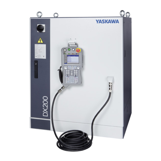
Page 36: Technical Data
Technical data Technical data Basic specifications robot controller DX200 Type: Cabinet: Dimensions (H x L x W) 1000 x 800 x 650 Mass 140 - 180 kg Cooling System Indirect cooling Ambient temperature 0° C to + 45° C Relative humidity... - Page 37 Technical data User Alarm Display Alarm messages for peripheral de- vices. Alarmdisplay Alarm message, troubleshooting, previous alarm records I/O diagnosis Simulated enable/disable signals possible. T.C.P. Calibration Automatic calculation of tool center point (TCP). Security: Specification 2-channel safety system (emergency stop, safety interlock) 3-position hold-to-run button, European safety standard (EN ISO 10218-1).
-
Page 38: Programming Pendant Specifications
Technical data Programming pendant specifications Programming pendant: material Reinforced thermoplastic enclosure with a detachable suspending strap. Dimensions (L x H x W) 1000 x 800 x 650 Mass 0.986 kg Displayed units TFT Color liquid crystal display, VGA (640 × 480), Touch panel. - Page 39 Technical data Start key Keys for movement types Hold key 3-position hold-to-run button Emergency stop button Optional position of the 3-position hold-to-run button Insertion slot for CF-Card Cursor key Page key Color display with touch screen "SELECT" selection key Menu area Speed keys Key switch for selecting the operating mode...
- Page 40 Technical data Servo On Released = OFF Squeezed tightly = OFF Squeezed = ON...
-
Page 41: Maintenance And Inspection
Maintenance and inspection Maintenance and inspection Periodic inspection DANGER! Death from electrical shock, risk of injury and fire due to short circuit Do not touch the cooling fan or other equipment while the power is turned ON. Carry out the following inspections. Components Inspection Method... -
Page 42: Cooling Fan Inspections
Maintenance and inspection Cooling fan inspections Inspect the cooling fans as required. A defective fan can cause the robot controller to malfunction because of excessive high temperatures inside. The interior circulation fan and backside duct fan normally operate while the power is turned ON. -
Page 43: Inspection Of The Enabling Switch
Maintenance and inspection Inspection of the enabling switch The programing pendant is equipped with a 3-position enable switch. Perform the following operation to confirm the enable switch operates. 1. Set the mode switch with key on the programming pendant to "TEACH". Fig. -
Page 44: Check Battery Unit
Maintenance and inspection Check battery unit The robot controller has a battery unit that backs up the important program files for user data in the CMOS memory. A battery alarm indicates when a battery has expired and must be replaced. The programming pendant display and the message "Memory battery weak"... -
Page 45: Open Phase Check
Maintenance and inspection Open Phase Check Check Item Operation Lead cable check Confirm if the lead cable for the power supply is wired as shown in the following without any falling out, looseness or breaking from the connecting part. Input Power Supply Check the open phase voltage of input power supply with an elec- Check tric tester. - Page 46 Maintenance and inspection 1(R) 3(S) 5(T) (Q1M) 2(U) 4(V) 6(W) AC400-415-440V/200V CN555 Fig. 7-5: Open Phase Check Power Supply X4 Converter Main switch Power Supply Contactor Unit Transfer Filters Fuse...
-
Page 47: Description Of Units And Circuit Boards
Description of Units and Circuit Boards Description of Units and Circuit Boards • Cautions for connection of dual input signals. Please follow the safety instructions in chapter 1.7 "Safety" on page 10. CAUTION! Connect the switch (contact), which at the same time switches the 2-channel signals ON and OFF. -
Page 48: Power On Unit
Description of Units and Circuit Boards Power ON unit The power ON unit consists of the power ON control circuit board (JARCR-YPC21-1) and the main circuit contactor and the line filter. It turns the main circuit control contactor ON and OFF using the signal for the servo power control from the machine safety I/O logic circuit board, and supplies power (3-phase AC200/220V) to the converter. -
Page 49: Axes Control Circuit Board
Description of Units and Circuit Boards Axes control circuit board 8.2.1 Major axes control circuit board The major axes control circuit board controls the servomotors of the robot’s six axes. It also controls the converter and the PWM amplifiers. Mounting an external axes control circuit board of an option makes it possible to control the servomotor of nine axes, including the robot axes. -
Page 50: External Axes Control Circuit Board
Description of Units and Circuit Boards 8.2.2 External axes control circuit board An external axes control circuit board is an optional, and it can control the additional three axes. It can be mounted on the external axes control circuit board. STO control signal I/F (CN524) External axes control circuit board STO control signal I/F (CN523) -
Page 51: Cpu Unit Configuration
Description of Units and Circuit Boards CPU unit configuration CPU unit consists of circuit board racks (flame, back circuit board, PCI riser circuit board), CPU circuit board, robot I/F circuit board and the machine safety CPU circuit board. The CPU unit contains only circuit board racks and CPU circuit boards. Be sure that it does not contain robot I/F circuit board and the machine safety CPU circuit board. -
Page 52: Unit And Circuit Board In The Cpu Unit
Description of Units and Circuit Boards 8.3.1 Unit and circuit board in the CPU unit 8.3.1.1 CPU board The entire system is controlled with this circuit board. It controls the display on the programming pendant, the control keys and the movements, and it calculates the interpolation. - Page 53 Description of Units and Circuit Boards • Input Rating Input Voltage: 200/240VAC Voltage Fluctuation Range: +10% to -15% (170 to 242VAC) Frequency: 50/60Hz ± 2Hz (48 to 62Hz) • Output Voltage DC + 5V DC +24V (24V1: System, 24V2: I/O, 24V3: Brake) •...
-
Page 54: Machine Safety I/O Logic Circuit Board
Description of Units and Circuit Boards Machine safety I/O logic circuit board Followings are the main functions of machine safety I/O logic unit. It processes external safety signals with the dual processing circuits and control ON/OFF of the main circuit control contactor of the power ON unit according to conditions. Followings are the main functions of machine safety I/O Logic unit. -
Page 55: Connection For Tool Shock Sensor (Shock)
Description of Units and Circuit Boards 8.5.1 Connection for tool shock sensor (SHOCK) Directly to the tool shock sensor signal line 1. Disconnect the minus SHOCK (-) and +24V2 pin terminal from the DINAMIC connector, the machine safety I/O logic circuit board (YSF22-CN214). The pin terminal for the shock sensor is attached on the right side of the controller. - Page 56 Description of Units and Circuit Boards With the cable that is built into the robot 1. Disconnect the minus SHOCK (-) and +24V2 pin terminal from the DINAMIC connector, the machine safety I/O logic circuit board (YSF22-CN214). The pin terminal for the shock sensor is attached on the right side of the controller.
-
Page 57: Machine Safety Terminal Block Circuit Board (Jancd-Yfc22-E)
Description of Units and Circuit Boards Machine safety terminal block circuit board (JANCD-YFC22- The machine safety terminal block circuit board (JANCD-YFC22-E) is for the system external signal to connect with the safety I/O signals. For connection, refer to the connection diagrams of each item. 26-50 -AE4 1-25... - Page 58 Description of Units and Circuit Boards Signal name Connec- Double Function Factory setting tion no. channel SAFF_1+ Possible Safety plug Short-circuit with a jumper SAFF_1- Used to turn OFF the servo cable power if the door on the SAFF_2+ safeguarding is opened. SAFF_2- Connect to the interlock sig- nal from the safety plug on...
- Page 59 Description of Units and Circuit Boards Signal name Connec- Double Function Factory setting tion no. channel SSP+ Slow speed mode selection Short-circuit with a jumper SSP- Used to determine the cable speed of the test run when the FST (full-speed test) signal input circuit is open.
- Page 60 Description of Units and Circuit Boards Signal name Connec- Double Function Factory setting tion no. channel ONEN1_1+ Possible SERVO-ON enable Short-circuit with a jumper ONEN1_1- Connected to use a function cable which distributes the robot ONEN1_2+ system to the multiple servo ONEN1_2- areas, and turns the servo ONEN2_1+...
- Page 61 Description of Units and Circuit Boards Signal name Connec- Double Function Factory setting tion no. channel GSIN1_1+ Possible Universal safety input Open GSIN1_1- The universal safety input signal is used in the safety GSIN1-2+ logical circuit function. GSIN1_2- GSIN2_1+ Possible GSIN2_1- GSIN2_2+ GSIN2_2-...
-
Page 62: External Emergency Stop Signal
Description of Units and Circuit Boards Signal name Connec- Double Function Factory setting tion no. channel AIN_COM Universal input (SERVO) Open AXIN1 Used to input the universal signal from the external de- AXIN2 vice. AXOUT1 Universal output (SERCO) Open AXOUT2 Used to output the universal signal to the external de- vice. - Page 63 Description of Units and Circuit Boards Safety plug This signal is used to turn OFF the servo power if the door of the protective device is opened. Connect to the interlock signal from the safety plug on the safeguarding door. If the interlock signal is input, the servo voltage is turned ON, as long as the signal is ON.
-
Page 64: Safety Plug
Description of Units and Circuit Boards Installation of safety plug NOTICE Observe DIN EN ISO 10218-2 with respect to the safety measures. Installation of Saftey Plug Robot working area Safety casing Service door Emergency shut-off Plug Safety plug If the SERVO power is ON when the interlock signal is input, the SERVO power turns OFF. As long as the interlock signal is active, the SERVO power cannot be turned ON. -
Page 65: External Enable Switch
Description of Units and Circuit Boards 8.10 External enable switch This signal is used to connect Enable switch other than the one on the programming pendant when two people are teaching. CAUTION! Injuries and machine damages caused by short-circuit Jumpers are installed at the factory. If the jumpers are not removed, the external emergency stop will not work even with incoming signal. -
Page 66: Full Speed Test
Description of Units and Circuit Boards 8.11 Full speed test This signal is used to reset the slow speed limit for the test run in the teach mode. If this signal input circuit is short-circuited, the speed of the test run becomes 100% in the play mode. - Page 67 Description of Units and Circuit Boards 2. The message "Full-speed test mode" is displayed as follows when the setting is finished. Operation Method When the full-speed test mode is set, operation speed is set depending on the setting of manual speed as follows. At the time of setting the full-speed mode, the setting of manual speed shifts to Inching automatically.
-
Page 68: Slow Speed Mode
Description of Units and Circuit Boards 8.12 Slow speed mode This signal is used to determine the speed of the test run when the FST (full-speed test) signal input circuit is open. Open: Second slow speed (2%) Short circuit: First slow speed (16%) CAUTION! Injuries and machine damages caused by short-circuit Jumpers are installed at the factory. -
Page 69: External Servo-On
Description of Units and Circuit Boards -X18 (JANCD-YSF22-E) CN219 EXHOLD+ EXHOLD- Fig. 8-10: Connection for external hold Robot controller Remove the jumper cable I/O terminal (machine safety) External hold I/O board (machine safety) 8.14 External SERVO-ON External SERVO-ON This signal is used to connect the servo ON switch of an external operation device. If the signal is input, the servo power is turned ON. -
Page 70: Sysrun Signal Output
Description of Units and Circuit Boards 8.15 SYSRUN Signal Output This signal is used to check whether the robot control status is normal or abnormal. This signal is output on the following conditions. Fig. 8-12: (1) Connection for SYSRUN signal output Main power supply ON/OFF SYSRUN ON/OFF Robot control status normal/abnormal... -
Page 71: External Axes Overrun
Description of Units and Circuit Boards 8.16 External axes overrun CAUTION! Injury and material damage in case of a non-functional signal Jumper cables are installed at the factory. If the cables are not removed, injury or damage to machinery may result and the external emergency stop will not work even if the signal is input. - Page 72 Description of Units and Circuit Boards -X18 (JANCD-YSF22-E) CN219 OT2_1+ OT2_1- OT2_2+ OT2_2- OT3_1+ OT3_1- OT3_2+ OT3_2- OT4_1+ OT4_1- OT4_2+ OT4_2- Fig. 8-15: Connection for external axis overrun (multiple lines) Robot controller Turn ON/OFF at the same time I/O-Terminal (machine safety) External axis overrun 2.
-
Page 73: Servo-On Enable Input
Description of Units and Circuit Boards 8.17 SERVO-ON enable input Connect the ONEN signal lines to enable the function to turn ON or OFF the servo power supply of an individual servo when a robotic system is divided into areas. Because these signals are not used for units of standard specifications, a jumper cable is connected as shown in the following figure. -
Page 74: Emergency Stop Button Output
Description of Units and Circuit Boards 8.18 Emergency stop button output The extra contact output terminals of the emergency stop button on the programming pendant are provided on the terminal block on the cabinet door. These contacts are always valid no matter if the robot controller power supply is ON or OFF. CAUTION! Damage to property caused by short-circuit ... -
Page 75: Universal Safety Input
Description of Units and Circuit Boards 8.19 Universal safety input The universal safety input signal is used in the safety logic circuit function. universal safety input. -X18 (JANCD-YSF22-E) CN219 GSIN1_1+ GSIN1_1- GSIN1_2+ GSIN1_2- Fig. 8-18: Universal safety input Robot controller Universal safety input Machine safety terminal block circuit Turn ON/OFF at the same time... -
Page 76: Universal Safety Output
Description of Units and Circuit Boards 8.20 Universal safety output The universal safety output signal is used in the safety logic circuit function. For example, composing the circuit to output the status signal, such as the servo ON signal or the emergency stop button by the safety logic circuit function enables to output the signals to the external device. -
Page 77: Direct-In (Servo) 1 To 6
Description of Units and Circuit Boards 8.21 Direct-in (SERVO) 1 to 6 This signal is used to input a response signal in search functions. -X18 (JANCD-YSF22-E) (SRDA-EAXA21A) CN219 93,94 024V2 AXDIN1 AXDIN2 AXDIN3 AXDIN4 AXDIN5 AXDIN6 AXDIN_COM 91,92 +24V2 (JANCD-YFC22-E) (JANCD-YSF22-E) (SRDA-EAXA21A) CN219... -
Page 78: Universal Input (Servo)
Description of Units and Circuit Boards 8.22 Universal input (SERVO) Connect when use the universal signal -X18 (JANCD-YSF22-E) (SRDA-EAXA21A) CN219 93,94 024V2 AXIN1 AXIN2 AXIN_COM 91,92 +24V2 Fig. 8-21: Universal input (SERVO) Robot controller Major axes control circuit board Machine safety terminal block circuit Universal input (SERVO) board Machine safety I/O logic ciruit board... -
Page 79: Universal I/O Circuit Board (Jancd-Yio22-E)
Description of Units and Circuit Boards 8.24 Universal I/O circuit board (JANCD-YIO22-E) Four digital I/O connectors for the robot universal I/O are provided: 40 inputs and 40 outputs. The I/Os are divided into two types: universal I/O and specific I/O. The I/O assignment differs depending on the application. - Page 80 Description of Units and Circuit Boards NOTICE When connecting an inductive load to the output circuit, connect a flyback (snubber) diode in parallel to the inductive load to suppress the surge voltage. Not using a fly-wheel diode may damage the output circuit. When connecting a load with a large inrush current such as a lamp, connect a current limiting resistance in series to the load, so that the output current does not exceed its maximum value.
- Page 81 Description of Units and Circuit Boards • Example of SERVO ON Sequence Circuit from External Device Only the rising edge of the SERVO ON signal is valid. This signal turns ON the robot SERVO power supply. The set and reset timings are shown in the following. SERVO ON PB SERVO ON confirmation SERVO_ON command...
- Page 82 Description of Units and Circuit Boards • Example of start sequence circuit from external device Only the rising edge of the external start signal is valid. This signal starts the robot. Set this signal with the interlock configuration which determines whether operation can be started. The playback signal (RUNNING) confirms that the robot is actually moving.
- Page 83 Power supply circuit for I/O (+24 VU, 024 VU) has 3.15A fuses (F1, F2). Install the external power supply outside the DX200 to avoid electric noise problems. If the internal power supply is selected and the external power supply is connected to CN303-1 to -3 and CN303-2 to -4, do not connect the external power supply line to the +24VU and 0VU terminals.
-
Page 84: Brake Control Circuit Board (Jancd-Ybk21-3E)
Description of Units and Circuit Boards 8.25 Brake control circuit board (JANCD-YBK21-3E) The brake control circuit board controls ON/OFF of the brakes of total nine axes (Robot + external axes) according to the command signal from the major axes control circuit board (SRDA-EAXA21A). -
Page 85: Converter (Srda-Coa30A21B-E)
Description of Units and Circuit Boards 8.26 Converter (SRDA-COA30A21B-E) The converter (SRDA-COA30A21B-E) exchanges the power supply (3-phase: AC200/ 220V) supplied by the power ON unit for DC power supply and supplies the power to the amplifier module (PWM amplifiers). Grounding detection input (CN554) Converter control signal (CN553) Monitor/Alarm indication LED DC control power supply (CN551) -
Page 86: Capacitor Module (Srda-Cua Aa)
Description of Units and Circuit Boards Capacitor module (SRDA-CUA AA) 8.27 The capacitor module smooth the DC voltage (PN voltage) created in the converter and also save the electric energy. There are two type of the capacitors shown below: •... -
Page 87: Amplifier Module (Sdra-Sda A01A-E)
Description of Units and Circuit Boards Amplifier module (SDRA-SDA A01A-E) 8.28 The amplifier module exchanges the DC power supply supplied by a converter for a 3- phase motor power source and outputs to each servo motor. Main circuit power supply input (CN583) Control power supply input (CN582) PWM signal (CN581) Motor power output (CN584) -
Page 88: Assignment Of General I/O Signal
Description of Units and Circuit Boards 8.29 Assignment of general I/O signal NOTICE Damage to property caused by short-circuit For details on wiring, see the circuit diagram. JANCD-YIO22-E -AE7 -CN306 assignment interface board &EFA/14.4 IN009 20040 -AE7-CN306 -XD306 IN010 20041 IN011 20042 IN012... - Page 89 Description of Units and Circuit Boards JANCD-YIO22-E -AE7 -CN307 &EFA/14.4 assignment interface board IN017 20050 -AE7-CN307 -XD307 IN018 20051 IN019 20052 IN020 20053 IN021 20054 IN022 20055 IN023 20056 IN024 20057 024VU NC14 NC15 NC16 NC17 024VU 024VU OUT017 30050 OUT017 30050 OUT018...
- Page 90 Description of Units and Circuit Boards JANCD-YIO22-E -CN308 -AE7 &EFA/14.4 assignment interface board 20010 -AE7-CN308 -XD308 20011 20012 20013 20014 20015 20016 20017 20020 20021 20022 20023 024VU 024VU 30010 30011 30012 30013 30014 30015 30016 30017 30020 30021 30022 30023 NC19 NC20...
- Page 91 Description of Units and Circuit Boards JANCD-YIO22-E -AE7 -CN309 assignment interface board &EFA/14.4 20024 -AE7-CN309 -XD309 20025 20026 20027 IN001 20030 IN002 20031 IN003 20032 IN004 20033 IN005 20034 IN006 20035 IN007 20036 IN008 20037 024VU 024VU 30024 30025 30026 30027 OUT001 30030...
- Page 92 Description of Units and Circuit Boards Logical number Input name / Function 20010 EXTERNAL START Functions the same as the [START] button in the programming pendant. Only the rising edge of the signal is valid. It starts robot operation (playback). This signal is invalid if external start is pro- hibited from the playback condition display.
- Page 93 START command. This signal turns OFF when the SERVO power supply turns OFF. It can be used for DX200 status diagnosis for an external start. 30012 TOP OF MASTER JOB This signal signifies that the execution position is the top of the master job.
-
Page 94: Arc Welding
START command. This signal turns OFF when the SERVO power supply turns OFF. It can be used for DX200 status diagnosis for an external start. 30012 TOP OF MASTER JOB This signal signifies that the execution position is the top of the mas- ter job. -
Page 95: Handling
I/O Name / Function 20026 TOOL SHOCK SENSOR This is normally ON (NC) signal input. When it turns OFF, an DX200 displays a message "HAND TOOL SHOCK SENSOR OPERATING" and a HOLD is applied. The releasing in teach mode is done on the handling application diagnostic display. -
Page 96: Spot Welding
Description of Units and Circuit Boards 8.29.4 Spot welding Logical num- Input name / Function 20022 WELDING ON/OFF (from sequencer) This signal inputs the welding ON/OFF selector switch status from the sequencer in the interlock unit. The WELD ON/OFF signal is output to the Power Source according to this signal and the robot status. - Page 97 Description of Units and Circuit Boards Logical num- Input name / Function STICK DETECTION This signal indicates an abnormal welding result or Power Source’s er- ror. Alarm occurs and the manipulator stops if this signal is input during welding. GUN FULL OPEN DETECTION This signal indicates that the stroke of the double stroke gun is full open.
- Page 98 Description of Units and Circuit Boards Logical num- Input name / Function STROKE CHANGE1 SINGLE SOLENOID DOUBLE SOLENOID This is a signal, when a double stroke gun is used, to change the open stroke of the welding gun. GUN PRESS COMMAND This outputs gun press command.
-
Page 99: Jancd-Yew01-E Circuit Board (Standard)
Description of Units and Circuit Boards 8.29.5 JANCD-YEW01-E circuit board (Standard) JANCD-YEW01-E Circuit Board: Analog outputs ´ 2 ports, Analog inputs ´ 2 ports + Status signal I/O of a Welder. MR Connector MS Connector Logical Connector Signal Name Number Pin No. -
Page 100: The List Of The Equipment Configuration By Model
Description of Units and Circuit Boards 8.29.6 The list of the Equipment configuration by model MA1440/MH12 Model ERER-MA1440/MH12-A00 Type 1000 x 800 x 650 Dimension W x H x D (mm) NF32-SVF 3P 15A Breaker JZNC-YPS21-E Control power supply unit JZNC-YRK21-1E CPU unit JANCD-YCP21-E... - Page 101 Description of Units and Circuit Boards MS210/MH225 Model ERER-MS210/MH225-A00 Type 1000 x 800 x 650 Dimension W x H x D (mm) NF32-SVF 3P 30A Breaker JZNC-YPS21-E Control power supply unit JZNC-YRK21-1E CPU unit JANCD-YCP21-E CPU circuit board JANCD-YBB21-E Back circuit board JANCD-YBB22-E PCI raiser circuit board JANCD-YIF01-2E...
- Page 102 Description of Units and Circuit Boards MS165/MH180 Model ERER-MS165/MH180-A00 Type 1000 x 800 x 650 Dimension W x H x D (mm) NF32-SVF 3P 30A Breaker JZNC-YPS21-E Control power supply unit JZNC-YRK21-1E CPU unit JANCD-YCP21-E CPU circuit board JANCD-YBB21-E Back circuit board JANCD-YBB22-E PCI raiser circuit board JANCD-YIF01-2E...
-
Page 103: Robot Controller Specification
Robot controller specification Robot controller specification WARNING! Make sure that there is no one within the P-point maximum envelope of the robot and that you are in a safe place before turning ON the robot controller power. Injury may result from collision with the robot to anyone entering the P-point maximum envelope of the robot. -
Page 104: Specification List
Robot controller specification Specification list Controller Dimension (W x H x D) 800 x 1000 x 600 Weight approx. 180 kg Protection class IP54 (The back fan is IP2X.) Cooling system Indirect cooling Ambient temperature 0°C to + 45°C (During operation) -10°C to + 60°C (During transit and storage) Relative humidity 10% to 90% RH (non-condensing) -
Page 105: Function List
Robot controller specification Function list Programming pendant operation Coordinate • Joint System • Rectangular/Cylindrical • Tool • User Coordinates Modification of Teach- • Adding ing Points • Deleting • Correcting (Robot axes and external axes respectively can be corrected) Inching Operation Possible Path Confirmation •... - Page 106 Robot controller specification Programming pendant operation Operation Time • Control power-on time Display • SERVO power-on time • PLAYBACK time • Operation time • Work time Alarm Display • Alarm message • Troubleshooting • Previous alarm records I/O Diagnosis Simulated enabled/disabled output possible T.C.P.
-
Page 107: Programming Pendant
Robot controller specification Programming Pendant Type JZRCR-YPP03-1 or JZRCR-YPP13-1 Material Reinforced thermoplastic enclosure with a detachable sus- pending strap Dimensions 169 x 314.5 x 50 mm (excluding protrusions) (W x H x D) in mm Material Reinforced plastic Displayed Units TFT Color liquid crystal display, VGA (640 x 480) Touch panel Operated Units... -
Page 108: Device Configuration
Robot controller specification Device configuration The robot controller is comprised of individual units and modules (circuit boards). Malfunctioning components can generally be easily repaired after a failure by replacing a unit or a module. This section explains the configuration of the robot controller equipment. ... - Page 109 Robot controller specification Cooling System of the controller interior The backside duct fan draws in air from the air intake and expels it from the air outlet to cool the SERVOPACK. The fan mounted inside the door circulates the air to keep temperature even throughout the interior of the robot controller.
-
Page 110: 10 Recommended Spare Parts List
Product performance cannot be guaranteed when using spare parts from any company other than YASKAWA. NOTICE Please contact your YASKAWA branch office if you need spare or replacement parts. Brake control board (-AE5), backside CPU unit (-AE1) of axis control board Axis control board (-AE6.0) - Page 111 Recommended spare parts list -TA7 -TA8 -TA9 (Option) (Option) (Option) -TA4 -TA6 -TA5 -TA1 -TA3 -TA2 Fig. 10-1: SERVOPACK (-TA1 to -TA9) The SERVOPACK types is different depending on robot model...
- Page 112 Recommended spare parts list Brake control board (-AE5), backside CPS unit (-AE3) of axis control board Axis control board (-AE6.0) I/O Terminal option Ex. axis control board (-AE6.1) Machine Safety I/O logic board (-AE4) Safety functional board (-AE6.2 Functional safety (-X181) option Terminal (-X9) Machine safety terminal board (-X18) Circuit breaker (-FS1)
- Page 113 Recommended spare parts list -TA7 -TA8 -TA9 (Option) (Option) (Option) -TA4 -TA6 -TA5 -TA1 -TA3 -TA2 Fig. 10-2: SERVOPACK (-TA1 to -TA9) The SERVOPACK types is different depending on robot model Spare parts list robot controller for MA1440/MH12 Power supply JZNC-YPS21-E master 164754...
- Page 114 Recommended spare parts list Spare parts list robot controller for MA1440/MH12 Resistor SMVK500W6R0J A6103 Master/Slave 164775 Memory card MCF10P256MS(A00ACIYE) master 151281 Spare parts list robot controller for MS165/MH180 Power supply JZNC-YPS21-E master 164754 additional power JZNC-YPS02-E Slave E147571 supply Rack-circuit board JZNC-YRK21-1E master 164756...
- Page 115 164774 Resistor SMVK500W2R0J A5978 Master/Slave E143574 Memory card MCF10P256MS(A00ACIYE) master 151281 NOTICE Product performance cannot be guaranteed when using spare parts from any company other than YASKAWA. Please contact your YASKAWA branch office if you need spare or replacement parts.
- Page 116 YASKAWA Headquarter...