Table of Contents
Table of Contents

Related Manuals for Asus EX-B250M-V3


Summary of Contents for Asus EX-B250M-V3
- Page 1 EX-B250M-V3...
- Page 2 Product warranty or service will not be extended if: (1) the product is repaired, modified or altered, unless such repair, modification of alteration is authorized in writing by ASUS; or (2) the serial number of the product is defaced or missing.
-
Page 3: Table Of Contents
Contents Safety information ..................iv About this guide ..................iv Package contents ..................vi EX-B250M-V3 specifications summary ............. vi Chapter 1: Product introduction Motherboard overview ................1-1 Central Processing Unit (CPU) ..............1-6 System memory ..................1-7 Chapter 2: BIOS information BIOS setup program ................. -
Page 4: Safety Information
Safety information Electrical safety • To prevent electrical shock hazard, disconnect the power cable from the electrical outlet before relocating the system. • When adding or removing devices to or from the system, ensure that the power cables for the devices are unplugged before the signal cables are connected. If possible, disconnect all power cables from the existing system before you add a device. -
Page 5: Conventions Used In This Guide
Refer to the following sources for additional information and for product and software updates. ASUS websites The ASUS website provides updated information on ASUS hardware and software products. Refer to the ASUS contact information. Optional documentation Your product package may include optional documentation, such as warranty flyers, that may have been added by your dealer. -
Page 6: Package Contents
* Hyper DIMM support is subject to the physical characteristics of individual CPUs. Please refer to Memory QVL (Qualified Vendors List) for details. ** Refer to www.asus.com for the Memory QVL(Qualified Vendors List). Integrated Graphics Processor - Intel HD Graphics support ®... - Page 7 USBGuard - 120% higher voltage tolerance ASUS 5X PROTECTION III - ASUS SafeSlot Core - Fortified PCIe slot prevents damage - ASUS LANGuard - surge-protected networking - ASUS DIGI+ VRM - Stable power supply - ASUS stainless steel back I/O - 3X more durable...
- Page 8 1 x System panel connector 64 Mb Flash ROM, UEFI AMI BIOS, PnP, DMI3.0, WfM2.0, SM BIOS 3.0, ACPI BIOS features 5.0, Multi-language BIOS, ASUS EZ Flash 3, F12 PrintScreen Manageability WfM 2.0, DMI 3.0, WOL by PME Support DVD...
-
Page 9: Motherboard Overview
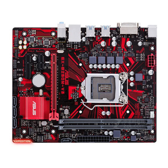
Place this side towards the rear of the chassis USB3_34 LGA1151 USB3_56 CHA_FAN LAN_USB78 AUDIO EX-B250M-V3 Realtek SATA6G_1 8111H PCIEX16 Super PCIEX1_1 64Mb BIOS Intel ® B250 SPEAKER PCIEX4_1 AAFP USB3_12 SATA6G_4 SATA6G_3 SATA6G_2 USB910 USB1112 F_PANEL Scan the QR code to get the detailed pin definitions. ASUS EX-B250M-V3... - Page 10 • For a fully configured system, we recommend that you use a power supply unit (PSU) that complies with ATX 12 V Specification 2.0 (or later version) and provides a minimum power of 350 W. • DO NOT forget to connect the 4-pin/ 8-pin EATX +12V power plug. Otherwise, the system will not boot up. • We recommend that you use a PSU with higher power output when configuring a system with more power-consuming devices or when you intend to install additional devices. The system may become unstable or may not boot up if the power is inadequate. • If you are uncertain about the minimum power supply requirement for your system, refer to the Recommended Power Supply Wattage Calculator at http://support.asus.com/PowerSupplyCalculator/PSCalculator. aspx?SLanguage=en-us for details. Intel LGA1151 CPU socket ® Install Intel LGA1151 CPU into this surface mount LGA1151 socket, which is ® designed for 7th/ 6th Generation Intel Core™ i7 / i5 / i3, Pentium , and Celeron ® ® ® processors. For more details, refer to Central Processing Unit (CPU). DDR4 DIMM slots Install 2 GB, 4 GB, 8 GB, and 16 GB non-ECC DDR4 DIMMs into these DIMM sockets.
- Page 11 USB 3.0 connector (20-1 pin USB3_12) Connect a USB 3.0 module to this connector for additional USB 3.0 front or rear panel ports. This connector complies with USB 3.0 specifications and provide faster data transfer speeds of up to 5 Gbps, faster charging time for USB-chargeable devices, optimized power efficiency, and backward compatibility with USB 2.0. USB 2.0 connectors (10-1 pin USB910, USB1112) Connect a USB module cable to any of these connectors, then install the module to a slot opening at the back of the system chassis. These USB connectors comply with USB 2.0 specifications and supports up to 480Mbps connection speed. TPM connector (14-1 pin TPM) Connect a Trusted Platform Module (TPM) system to this connector to +3VSB F_CLKRUN S_PCIRST#_TBD F_SERIRQ enhance network security, protect digital F_FRAME# identities, and ensure platform integrity. F_LAD3 C_PCICLK_TPM F_LAD2 F_LAD1 F_LAD0 PIN 1 ASUS EX-B250M-V3...
-
Page 12: Irq Assignments For This Motherboard
Front panel audio connector (10-1 pin AAFP) This connector is for a chassis-mounted front panel audio I/O module that supports either HD Audio or legacy AC`97 audio standard. Connect one end of the front panel audio I/O module cable to this connector. • We recommend that you connect a high-definition front panel audio module to this connector to avail of the motherboard’s high-definition audio capability. • If you want to connect a high-definition front panel audio module to this connector, set the Front Panel Type item in the BIOS setup to [HD Audio]. If you want to connect an AC’97 front panel audio module to this connector, set the item to [AC97]. By default, this connector is set to [HD Audio]. PCI Express 3.0/2.0 x1 slot This motherboard supports PCI Express 3.0/2.0 x1 network cards, SCSI cards, and other cards that comply with the PCI Express specifications. PCI Express 3.0/2.0 x4 slot This motherboard supports PCI Express 3.0/2.0 x4 RAID cards, SSDs, and other cards that comply with the PCI Express specifications. PCI Express 3.0/2.0 x16 slot This motherboard has one PCI Express 3.0/2.0 x16 slot that supports PCI Express 3.0/2.0 x16 graphic cards complying with the PCI Express specifications. -
Page 13: Rear Panel Connectors
Line Out port (lime). This port connects to a headphone or a speaker. In the 4.1, 5.1 and 7.1-channel configurations, the function of this port becomes Front Speaker Out. Microphone port (pink). This port connects to a microphone. Refer to the audio configuration table for the function of the audio ports in 2.1, 4.1, 5.1, or 7.1-channel configuration. Audio 2.1, 4.1, 5.1, or 7.1-channel configuration Headset Port 4.1-channel 5.1-channel 7.1-channel 2.1-channel Light Blue (Rear panel) Line In Rear Speaker Out Rear Speaker Out Rear Speaker Out Lime (Rear panel) Line Out Front Speaker Out Front Speaker Out Front Speaker Out Pink (Rear panel) Mic In Mic In Bass/Center Bass/Center Lime (Front panel) Side Speaker Out ASUS EX-B250M-V3... -
Page 14: Central Processing Unit (Cpu)
USB 2.0 and USB 3.0 ports are controlled by the xHCI controller. Some legacy USB devices must update their firmware for better compatibility. DVI-D port. This port is for any DVI-D compatible device. DVI-D can not be converted to output from RGB Signal to CRT and is not compatible with DVI-I. PS/2 keyboard port (purple). This port is for a PS/2 keyboard. Central Processing Unit (CPU) This motherboard comes with a surface mount LGA1151 socket designed for 7th/ 6th Generation Intel Core™ i7/ i5/ i3, Pentium and Celeron processors. ® ® ® Unplug all power cables before installing the CPU. • Upon purchase of the motherboard, ensure that the PnP cap is on the socket and the socket contacts are not bent. Contact your retailer immediately if the PnP cap is missing, or if you see any damage to the PnP cap/socket contacts/motherboard components. • Keep the cap after installing the motherboard. ASUS will process Return Merchandise Authorization (RMA) requests only if the motherboard comes with the cap on the LGA1151 socket. • The product warranty does not cover damage to the socket contacts resulting from incorrect CPU installation/removal, or misplacement/loss/incorrect removal of the PnP cap. Chapter 1: Product introduction... -
Page 15: System Memory
Installing the CPU Apply the Thermal Interface Material to the CPU heatsink and CPU before you install the heatsink and fan if necessary. System memory Overview This motherboard comes with two Double Data Rate 4 (DDR4) Dual Inline Memory Module (DIMM) sockets. The figure illustrates the location of the DDR4 DIMM sockets: Channel Sockets DIMM_A1 Channel A DIMM_A1 DIMM_B1 Channel B DIMM_B1 • You may install varying memory sizes in Channel A and Channel B. The system maps the total size of the lower-sized channel for the dual-channel configuration. Any excess memory from the higher-sized channel is then mapped for single-channel operation. • Always install DIMMs with the same CAS latency. For optimal compatibility, we recommend that you install memory modules of the same version or date code (D/C) from the same vendor. Check with the retailer to get the correct memory modules. ASUS EX-B250M-V3... -
Page 16: Installing A Dimm
Use a maximum of 3GB system memory if you are using a 32-bit Windows OS. ® I nstall a 64-bit Windows OS if you want to install 4GB or more on the ® motherboard. F or more details, refer to the Microsoft support site at http://support.microsoft. ® com/kb/929605/en-us. • Memory modules with memory frequency higher than 2133 MHz and its corresponding timing or the loaded X.M.P. Profile is not the JEDEC memory standard. The stability and compatibility of these memory modules depend on the CPU’s capabilities and other installed devices. • The default memory operation frequency is dependent on its Serial Presence Detect (SPD), which is the standard way of accessing information from a memory module. Under the default state, some memory modules for overclocking may operate at a lower frequency than the vendor-marked value. • For system stability, use a more efficient memory cooling system to support a full memory load (2 DIMMs). • Refer to www.asus.com for the latest Memory QVL (Qualified Vendors List) Installing a DIMM To remove a DIMM Chapter 1: Product introduction... -
Page 17: Chapter 2: Bios Information
The BIOS setup screens shown in this section are for reference purposes only, and may not exactly match what you see on your screen. Visit the ASUS website at www.asus.com to download the latest BIOS file for this • motherboard. -
Page 18: I-Cafe
This item allows you to enable or disable the XHCI hand-off feature for operating system without XHCI hand-off support. ASUS EZ Flash 3 Utility Allows you to run ASUS EZ Flash 3. Press [Enter] to launch the ASUS EZ Flash 3 screen. Chapter 2: Getting started... -
Page 19: Main Menu
(RTC) RAM to clear the BIOS password. See section 1Motherboard overview for information on how to erase the RTC RAM. The Administrator or User Password items on top of the screen show the default • Not Installed. After you set a password, these items show Installed. ASUS EX-B250M-V3... -
Page 20: Advanced Menu
Advanced menu The Advanced menu items allow you to change the settings for the CPU and other system devices. Be cautious when changing the settings of the Advanced menu items. Incorrect field values can cause the system to malfunction. CPU Configuration The items in this menu show the CPU-related information that the BIOS automatically detects. -
Page 21: Monitor Menu
The onboard hardware monitor automatically detects the voltage output through the onboard voltage regulators. Select [Ignore] if you do not want to detect this item. Q-Fan Configuration The subitems in this menu allows you to configure the Q-Fan features. ASUS EX-B250M-V3... -
Page 22: Boot Menu
Boot menu The Boot menu items allow you to change the system boot options. Fast Boot This item allows you to accelerate the boot speed. Boot Configuration Boot Logo Display This item allows you to configure the boot logo display settings. Bootup NumLock State This item allows you to enable or disable power-on state of the NumLock. -
Page 23: Exit Menu
OS in Safe Mode, pressafter POST (Windows 8 not supported). • To select the boot device during system startup, press when ASUS Logo appears. Boot Override These items displays the available devices. The number of device items that appears on the screen depends on the number of devices installed in the system. -
Page 24: Appendix
Cet appareil est conforme aux normes CNR exemptes de licence d’Industrie Canada. Le fonctionnement est soumis aux deux conditions suivantes : (1) cet appareil ne doit pas provoquer d’interférences et (2) cet appareil doit accepter toute interférence, y compris celles susceptibles de provoquer un fonctionnement non souhaité de l’appareil. ASUS EX-B250M-V3... -
Page 25: Canadian Department Of Communications Statement
ASUS Recycling/Takeback Services ASUS recycling and takeback programs come from our commitment to the highest standards for protecting our environment. We believe in providing solutions for you to be able to responsibly recycle our products, batteries, other components as well as the packaging materials. - Page 26 Slovensky Spoločnosť ASUSTeK Computer Inc. týmto vyhlasuje, že toto Cijeli tekst EU izjave o sukladnosti dostupan je na: www.asus.com/support zariadenie vyhovuje základným požiadavkám a ostatým príslušným ustanoveniam príslušných smerníc. Celý text vyhlásenia o zhode pre štáty EÚ...
-
Page 27: Asus Contact Information
+1-510-739-3777 +1-510-608-4555 Web site http://www.asus.com/us/ Technical Support Support fax +1-812-284-0883 Telephone +1-812-282-2787 Online support http://qr.asus.com/techserv ASUS COMPUTER GmbH (Germany and Austria) Address Harkort Str. 21-23, 40880 Ratingen, Germany +49-2102-959931 Web site http://www.asus.com/de Online contact http://eu-rma.asus.com/sales Technical Support Telephone +49-2102-5789555 Support Fax... -
Page 28: Declaration Of Conformity
800 Corporate Way, Fremont Phone/Fax No: (510)739-3777/(510)608-4555 hereby declares that the product Product Name : Motherboard Model Number : EX-B250M-V3 Conforms to the following specifications: FCC Part 15, Subpart B, Unintentional Radiators Supplementary Information: This device complies with part 15 of the FCC Rules. Operation is subject to the...