Yamaha CLAVINOVA CLP-120 Service Manual
Hide thumbs
Also See for CLAVINOVA CLP-120:
- Owner's manual (80 pages) ,
- Bedienungsanleitung (80 pages)
Table of Contents
Quick Links
This document is printed on chlorine free (ECF) paper with soy ink.
CL 001671
20020401-158000
CLP-120
SERVICE MANUAL
CONTENTS
SPECIFICATIONS .............................................................................. 3
PANEL LAYOUT .................................................................................. 4
CIRCUIT BOARD LAYOUT ................................................................. 6
BLOCK DIAGRAM .............................................................................. 7
DISASSEMBLY PROCEDURE ........................................................... 8
LSI PIN DESCRIPTION .................................................................... 19
IC BLOCK DIAGRAM ........................................................................ 21
CIRCUIT BOARDS ........................................................................... 23
INSPECTION .................................................................................... 33
MIDI IMPLEMENTATION CHART ..................................................... 40
OVERALL CIRCUIT DIAGRAM
PARTS LIST
CLP-120
HAMAMATSU, JAPAN
1,752K-377
Printed in Japan '02, 03
Chapters
Table of Contents

Related Manuals for Yamaha CLAVINOVA CLP-120


Summary of Contents for Yamaha CLAVINOVA CLP-120
-
Page 1: Service Manual
CLP-120 SERVICE MANUAL CLP-120 CONTENTS SPECIFICATIONS ................3 PANEL LAYOUT .................. 4 CIRCUIT BOARD LAYOUT ..............6 BLOCK DIAGRAM ................7 DISASSEMBLY PROCEDURE ............8 LSI PIN DESCRIPTION ..............19 IC BLOCK DIAGRAM ................ 21 CIRCUIT BOARDS ................23 INSPECTION ..................33 MIDI IMPLEMENTATION CHART ............. -
Page 2: Important Notice
IMPORTANT NOTICE This manual has been provided for the use of authorized Yamaha Retailers and their service personnel. It has been assumed that basic service procedures inherent to the industry, and more specifically Yamaha Products, are already known and understood by the users, and have therefore not been restated. -
Page 3: Specifications
CLP-120 I SPECIFICATIONS Keyboard 88 (A-1 ~ C7) Sound Source AWM Stereo Sampling Polyphony 64 Notes Max. Voice Selections Effect Reverb, Effect, Brilliance Volume Master Volume Controls Dual, Metoronome, Transpose, Touch (Hard/Medium/Soft/Fixed), Functions, Speaker ON/OFF Recording/Playback 2-track recording/playback (1 user song), Tempo Adjustment, Synchro Start Pedal Damper, Sostenuto, Soft Demo Songs... -
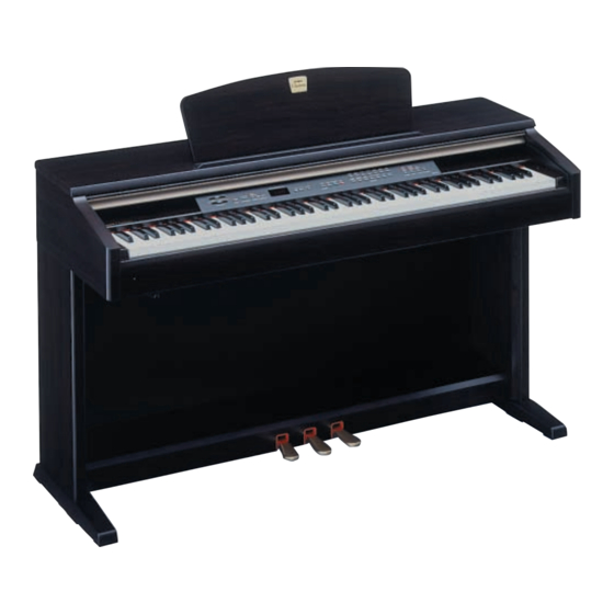
Page 4: Panel Layout
CLP-120 I PANEL LAYOUT Top Panel TEMPO/ OTHER VALUE TEMPO MASTER VOLUME TRACK TRACK START/STOP START/STOP FUNCTION /NO +/ YES PRESET MELLOW BRIGHT BRILLIANCE DEMO METRONOME TEMPO / FUNCTION SONG GRAND GRAND E.PIANO E.PIANO HARPSI- HARPSI- VIBRA- PIANO 1 PIANO 2 CHORD1 CHORD2 PHONE... - Page 5 CLP-120 POWER [MASTER VOLUME] [BRILLIANCE] [DEMO] METRONOME [START/STOP] [TEMPO/FUNCTION # LM] LED Display [-/NO]/[+YES] [PRESET] [TRACK1][TRACK2] SONG [START/STOP] [REC] Voice buttons [REVERB] [EFFECT] [TOUCH] [TRANSPOSE] [PEDAL] AUX OUT AUX IN [TO HOST] [HOST SELECT] MIDI [IN][OUT][THRU] [SPEAKER] [PHONES] Soft (Left) Pedal Sostenuto (Center) Pedal Damper (Right) Pedal...
-
Page 8: Disassembly Procedure
CLP-120 I DISASSEMBLY PROCEDURE Top Board Assembly (Time required: about 2 min) Before disassembling the top board assembly, shut up the key cover assembly completely to protect the key cover assembly from being scratched. 1-1. Remove the three (3) screws marked [48]. (Fig.1) 1-2. - Page 9 CLP-120 DJK Circuit Board (Time required: about 5 min) 3-1. Remove the top board assembly. (See Procedure 1) 3-2. Remove the jack unit. (See Procedure 2) 3-3. Remove the eight (8) screws marked [4a]. The DJK circuit board can then be removed. (Fig.3) MAJ Circuit Board (Time required: about 5 min) 4-1.
- Page 10 CLP-120 Panel Assembly (Time required: about 5 min) 6-1. Remove the top board assembly. (See Procedure 1) 6-2. Remove the key cover assembly. (See Procedure 5) 6-3. Remove the two (2) screws marked [51] and the six (6) screws marked [40]. The panel assembly can [40] then be removed.
- Page 11 CLP-120 End Block Assembly L, R (Time required: about 6 min for each) 9-1. Remove the top board assembly. (See Procedure 1) 9-2. Remove the key cover assembly. (See Procedure 5) 9-3. Remove the panel assembly. (See Procedure 6) 9-4. Remove the screw marked [45] for each side.
- Page 12 CLP-120 Keyboard Assembly (Time required: about 9 min) 12-1. Remove the top board assembly. (See Procedure 1) 12-2. Remove the key cover assembly. (See Procedure 5) 12-3. Remove the panel assembly. (See Procedure 6) 12-4. Remove either the rack assembly L or R. (See Procedure 8) 12-5.
- Page 13 CLP-120 Music Rest Assembly (Time required: about 1 min) 14-1. Remove the four (4) screws marked [39]. The music rest assembly can then be removed. (Fig.11) [39] Top View (Fig.11) [39]: Bind Head Tapping Screw-1 3.0X16 MFZN2BL (EP030310) Top Board Assembly Music Rest Assembly Back Board (Time required: about 2 min) 15-1.
- Page 14 CLP-120 Pedal Assembly (Time required: about 3 min) For safety, make sure to perform by two persons. 17-1. Spread soft cloth on the floor and lay down the unit carefully on its back. (Fig.13) 17-2. Remove the eight (8) screws marked [7]. The pedal assembly can then be removed.
- Page 15 CLP-120 Side Cover Assembly L, R (Time required: about 12 min for each) For safety, make sure to perform by two persons. To remove screws from the bottom, prepare a worktable or bolsters to set the main unit. 19-1. Remove the top board assembly. (See Procedure 1) 19-2.
- Page 16 CLP-120 20-7. Remove the screw marked [6a] to remove the PL circuit board. (Fig.19) 20-8. Remove the six (6) screws marked [6b] to remove the keyboard holder assembly. (Fig.19) 20-9. Remove the four (4) screws marked [7] to remove the angle K. (Fig.19) Holder Assembly, Keyboard Angle K Angle K...
- Page 17 CLP-120 Disassembling the GHD Keyboard (Time required: about 20 min) After inserting a round stick (Rod: TX000670) between the frame and keys, remove the circuit boards. (Fig.23) 24-1 Remove the keyboard assembly. (See Procedure 12) 24-2 GH-D_SW L circuit board. Remove the seven (7) screws marked [260a].
- Page 18 CLP-120 Assembling the GHD Keyboard 25-1 Hammer of White (Black) Key Place the keyboard assembly upside down, insert a hammer assembly into the frame, and put the stopper L88W on. (Fig.26) There are four kinds of hammers that differ in weight.
-
Page 19: Lsi Pin Description
CLP-120 I LSI PIN DESCRIPTION CONTENTS HG73C205AFD XU947C00 SWX00B (TONE GENERATOR) ........20 YMZ702-D XR632A00 KSN2 (Key Scanner) ..............21... - Page 20 CLP-120 HG73C205AFD (XU947C00) SWX00B TONE GENERATOR DM : IC007, 008 NAME I/O FUNCTION NAME I/O FUNCTION Initial clear CMA3 RFCLKI PLL Clock CMA8 Program address bus PLL Control CMA2 4 AVDD_PLL Power supply read signal AVSS_PLL Ground CMA1 Program address bus MODE0 SWX dual mode high byte effective signal...
-
Page 21: Ic Block Diagram
CLP-120 YMZ702-D (XR632A00) KSN2 (Key Scanner) GHDcl SW L: KSN2 NAME I/O FUNCTION NAME FUNCTION Ground Power supply Serial data Key block (open drein) Acknowledge/mode select Clock for serial data Initial clear MK15 TST1 Test mode MK14 TST2 (L,L: normal mode, others: test) MK13 29 XCKINH Inhibit of serial clock... - Page 22 CLP-120 TC7S00F(XG150A00) PC4570G2 (XF291A00) SC7SU04FEL(XI348A00) NAND DM: IC026 TC7SU04F (XY447A00) Dual Operational Amplifier lnverter Gate DM: IC013, IC022 DJK: IC001 MAJ: IC002 IN B +DC Voltage Output A Supply IN A Inverting Output B Input A Inverting Non-Inverting Input B Input A Non-Inverting -DC Voltage Supply...
-
Page 23: Table Of Contents
CLP-120 I CIRCUIT BOARDS CONTENTS DM Circuit Board (2NA-V849550) ................24 MAJ Circuit Board (2NA-V855420) ................26 DJK Circuit Board (2NA-V849600) ................28 PS Circuit Board (2NA-V001070) ................. 29 PNR Circuit Board (2NA-V849690) ................30 PNL Circuit Board (2NA-V849680) ................31 PEDAL Circuit Board (2NA-V233730) ................ -
Page 24: Gdm Circuit Board (2Na-V849550)
CLP-120 DM Circuit Board 2NA-V849550 to DJK-CN4... - Page 25 CLP-120 DM Circuit Board Note: See parts list for details of circuit board component parts.
-
Page 26: Gmaj Circuit Board (2Na-V855420)
CLP-120 MAJ Circuit Board 2NA-V855420... - Page 27 CLP-120 MAJ Circuit Board Note: See parts list for details of circuit board component parts.
-
Page 28: Gdjk Circuit Board (2Na-V849600)
CLP-120 DJK Circuit Board Note: See parts list for details of circuit board component parts. 2NA-V849600... -
Page 29: Gps Circuit Board (2Na-V001070)
CLP-120 PS Circuit Board to Power SW Note: See parts list for details of circuit board component parts. 2NA-V001070... -
Page 30: Gpnr Circuit Board (2Na-V849690)
CLP-120 PNR Circuit Board to DM-CN2 to DM-CN1 A’ Component Side A’ Note: See parts list for details of circuit board component parts. 2NA-V849690... -
Page 31: Gpnl Circuit Board (2Na-V849680)
CLP-120 PNL Circuit Board to MAJ-CN3 to DM-CN2 to DM-CN1 A’ Component Side A’ Note: See parts list for details of circuit board component parts. 2NA-V849680... -
Page 32: Gpedal Circuit Board (2Na-V233730)
CLP-120 PEDAL Circuit Board HP Circuit Board NORMAL ON OFF (HP. SW) PHONES SPEAKER Component Side PL Circuit Board Pattern Side PEDAL: 2NA-V233730 Note: See parts list for details of circuit board component parts. HP: 2NA-V858650 PL: 2NA-VN63760... - Page 33 CLP-120 I INSPECTION Preparation • To check the unit, following mesuring instruments are required. Level meter (JIS-C filter) Frequency counter • Set each control as follows. MASTER VOLUME: MAX BRILLIANCE: CENTER Voice: GRAND PIANO 1 PEDAL: OFF REVERB: OFF SPEAKER ON/OFF switch: NORMAL AUX IN, AUX OUT: Connect a load resistance to all terminals.
- Page 34 CLP-120 Table 1 Test Items 7 segment. LED Test Function and Judgment criteria (01: Version Checks ROM version. ‘P x.x ’ ‘U x.x . . ’ Make sure that the 7-seg.LED alternately indicates ‘P x.x ’ (version of the pro- gram) and ‘U x.x ’...
- Page 35 CLP-120 If the correct switch is pressed, the sine wave sounds on the pitch shown in the Table 2 and the 7segment LED indicates the next number. In addition, the LED lights up as for the LED-attached switch. If the wrong switch is pressed, the 7segment LED indicates ‘nG’. After the last switch is checked, the 7segment LED indicates ‘PAS’.
- Page 36 CLP-120...
- Page 37 CLP-120...
- Page 38 CLP-120...
- Page 39 CLP-120 Table 2 SW No. SWITCH NOTE DEMO METRONOME TEMPO/FUNCTION TEMPO M TEMPO L -/NO +/YES PRESET TRACK1 TRACK2 START/STOP GRAND PIANO1 GRAND PIANO2 E.PIANO1 E.PIANO2 HARPSICHORD1 HARPSICHORD2 VIBRAPHONE CHURCH ORGAN1 CHURCH ORGAN2 JAZZ ORGAN STRINGS1 STRINGS2 CHOIR GUITAR REVERB EFFECT TOUCH TRANSPOSE...
-
Page 40: Midi Implementation Chart
CLP-120 I MIDI IMPLEMENTATION CHART MIDI I mplementat ion Char t YAMAHA [Clavinova] Date: 24-OCT-2001 Model: CLP-130/120 MIDI Implementation Chart Version: 1.0 Function Transmitted Recognized Remarks Basic Default Channel Changed 1 - 16 1 - 16 Default Mode Messages Poly Mode only... -
Page 41
CLP-120 CLP-120 CIRCUIT DIAGRAM 1/3 (DM) to GHDcl SW L-CN1 PROGRAM ROM SRAM SRAM REGULATOR +3.3V REGULATOR +5V to MAJ-CN2 NAND SWX00B to DJK-CN4 NJM J78L05UA(XJ598A00) DEMULTIPLEXER REGULATOR +5V DM:IC023 SYSTEM RESET 1: OUTPUT 2: COMMON 3: INPUT SI-850L (XS346A00) REGULATOR +5V DM:IC027 DRIVER ARRAY... -
Page 42
CLP-120 CIRCUIT DIAGRAM (MAJ, DJK, PNR, PNL, HP, PL, PEDAL) CLP-120 to DM-CN1 to PS-CN2 REGULATOR +12V to DM-CN5 to DM-CN2 to HP-CN1 to PNL-CN301 to DM-CN4 L (L+R) L (L+R) OP AMP AUX OUT AUX IN 28CC1-8822664 SPEAKERS NORMAL (HP,SW) µPC24M12AHF(XU387A00) -
Page 43
CLP-120 CIRCUIT DIAGRAM (GH-D_SW H, GH-D_SW L, PS) CLP-120 GH-D_SW H 28CC1-8811214 GH-D_SW L Not install Install KSN2 Not install Not install 11ES4 (VB481900) DIODE PS:D1, D2 28CC1-8811214 to DM-CN3 1: ANODE 2: CATHODE 11ES4 TA1 (VF195600) DIODE PS:D1, D2 1: ANODE 2: CATHODE D3SBA20 (VN011300) -
Page 44: Parts List
CLP-120 CLP-120 PARTS LIST CONTENTS OVERALL ASSEMBLY ..........2 PANEL ASSEMBLY ..........15 MAIN UNIT ..............4 KEY COVER ASSEMBLY ........17 SIDE BOARD ASSEMBLY ......... 8 JACK UNIT ............... 18 PEDAL BOX ASSEMBLY ........... 9 HP JACK ASSEMBLY ..........18 PEDAL ASSEMBLY .......... - Page 45 CLP-120 I OVERALL ASSEMBLY Screw set 8 Headphone hanger set Front view Rear view...
-
Page 46: Overall Assembly
CLP-120 DESCRIPTION REMARKS PART NO. QTY RANK REF NO. OVERALL ASSEMBLY CLP-120 Overall Assembly (V821590) Overall Assembly (V821600) Overall Assembly (V821610) Overall Assembly (V821620) Overall Assembly (V821630) Overall Assembly (V938580) (V821640) Main Unit Main Unit (V821650) Main Unit (V821660) Main Unit (V821670) Main Unit (V938590) - Page 47 CLP-120 I MAIN UNIT Rear view Top view 1 Side view 14 15...
- Page 48 CLP-120 Bottom view Top view 2 Screw Set List Screw Ref.No. Parts No. Bind Head Tapping Screw-1 (EP030240) Truss Head Tspping Screw-1 (VU952600) Pan Head Screw (VV040700) Truss Head Tspping Screw-1 (EN630230) Bind Head Tapping Screw-1 (EP040230) Truss Head Tspping Screw-1 (VA076400) Truss Head Screw (V6207400) Truss Head Tspping Screw-1 (20338800) Guide Screw (VN887900)
-
Page 49: Main Unit
CLP-120 DESCRIPTION REMARKS PART NO. QTY RANK REF NO. MAIN UNIT CLP-120 Main Unit (V821640) Main Unit (V821650) Main Unit (V821660) Main Unit (V821670) Main Unit (V938590) Main Unit Sub Assembly (V821820) EP030240 3.5X12 MFZN2Y Bind Head Tapping Screw-1 Name Plate J (YMMA) (V821830) Name Plate... - Page 50 CLP-120 DESCRIPTION REMARKS PART NO. QTY RANK REF NO. EP600250 Bind Head Tapping Screw-B 3.0X8 MFZN2Y V 6 2 0 7 4 0 0 Truss Head Screw 4.0X16 MFZN2BL 2 0 3 3 8 8 0 0 Truss Head Tapping Screw-1 4X20 MFZN2Y VN887900...
-
Page 51: Side Board Assembly
CLP-120 I SIDE BOARD ASSEMBLY (L, R) *This figure shows a side cover assembly (L). Front view Side view PART NO. DESCRIPTION REMARKS QTY RANK REF NO. SIDE BOARD ASSEMBLY CLP-120 V 8 2 1 7 8 0 0 Side Board Assembly-L LEFT Side Board LEFT... -
Page 52: Pedal Box Assembly
CLP-120 I PEDAL BOX ASSEMBLY Front view Bottom view PART NO. DESCRIPTION REMARKS QTY RANK REF NO. PEDAL BOX ASSEMBLY CLP-120 Pedal Box Assembly (V821800) V 8 5 5 9 5 0 0 Pedal Box VU464300 Felt 115X12X2 RE V 0 0 5 3 7 0 0 Pedal Assembly 3SW PK-LF CB065520... -
Page 53: Pedal Assembly
CLP-120 PEDAL ASSEMBLY • Top view • Side view 100 110 • Bottom view PART NO. DESCRIPTION REMARKS QTY RANK REF NO. PEDAL ASSEMBLY CLP-120 V 0 0 5 3 7 0 0 Pedal Assembly 3SW PK-LF VU339700 Pedal Frame VU362000 Pedal Piece C CENTER... -
Page 54: Top Board Assembly
CLP-120 I TOP BOARD ASSEMBLY Top view Side view PART NO. DESCRIPTION REMARKS QTY RANK REF NO. TOP BOARD ASSEMBLY CLP-120 V 8 2 1 8 7 0 0 Top Board Assembly Top Board (V823660) VY891000 Stopper Rail, Music Score VV444100 Shoulder Screw VQ485800... -
Page 55: Music Rest Assembly
CLP-120 I MUSIC REST ASSEMBLY Rear view Side view PART NO. DESCRIPTION REMARKS QTY RANK REF NO. MUSIC REST ASSEMBLY CLP-120 V 8 2 4 7 8 0 0 Music Rest Assembly Music Rest (V824790) V 8 4 3 7 6 0 0 Hinge 1STEP 1.6mm YMMA VV965900... -
Page 56: Side Cover Assembly
CLP-120 I SIDE COVER ASSEMBLY (L, R) *This figure shows a side cover assembly (L). Front view Side view 7 10 PART NO. DESCRIPTION REMARKS QTY RANK REF NO. SIDE COVER ASSEMBLY CLP-120 V 8 2 1 8 9 0 0 Side Cover Assembly LEFT Side Cover... -
Page 57: End Block Assembly
CLP-120 I END BLOCK ASSEMBLY (L, R) Top view (L) Side view (R) Top view (R) Power switch assembly PART NO. DESCRIPTION REMARKS QTY RANK REF NO. END BLOCK ASSEMBLY CLP-120 End Block Assembly LEFT (V925890) V 9 3 5 1 0 0 0 End Block LEFT,NO BORE Angle, H... -
Page 58: Panel Assembly
CLP-120 I PANEL ASSEMBLY Top view 1 Bottom view 1 14 13 38 Bottom view 2 15 18 22 21 20 15 19 Bottom view 3 Top view 2 Screw Set List Screw Ref.No. Parts No. Bind Head Tapping Screw-B (EP600250) Bind Head Tapping Screw-B (EP600140) Bind Head Tapping Screw-1 (EP030230) Bind Head Tapping Screw-1 (EP030340) - Page 59 CLP-120 DESCRIPTION REMARKS PART NO. QTY RANK REF NO. Control Panel Holder B (V857710) 15X15X1 Felt (VU85070) ECT W=15 Adhesive Tape (ZL35000) 54X10X0.25 V 5 9 11 3 0 0 Dust Proof Cloth VU332300 Window, LED V 8 4 9 6 8 0 0 Circuit Board V 8 4 9 6 9 0 0 Circuit Board...
-
Page 60: Key Cover Assembly
CLP-120 I KEY COVER ASSEMBLY Bottom view 8 7 11 2b 2c 14 13 13 14 2b 2c PART NO. DESCRIPTION REMARKS QTY RANK REF NO. KEY COVER ASSEMBLY CLP-120 V 8 4 4 8 1 0 0 Key Cover Assembly (YMMA) Slide Cover (V844670) -
Page 61: Jack Unit
CLP-120 I JACK UNIT Top view Side view Bottom view PART NO. DESCRIPTION REMARKS QTY RANK REF NO. JACK UNIT CLP-120 Jack Unit (V826580) Jack Plate (V826590) V 8 5 5 4 2 0 0 Circuit Board V 8 4 9 6 0 0 0 Circuit Board EP600190 Bind Head Tapping Screw-B... -
Page 62: Power Supply Unit
CLP-120 I POWER SUPPLY UNIT Top view Front view PART NO. DESCRIPTION REMARKS QTY RANK REF NO. POWER SUPPLY UNIT CLP-120 V 0 0 1 0 2 0 0 Power Supply Unit V 0 0 1 0 3 0 0 Power Supply Unit V 0 0 1 0 4 0 0 Power Supply Unit... -
Page 63: Keyboard Assembly
CLP-120 I KEYBOARD ASSEMBLY... - Page 64 CLP-120 DESCRIPTION REMARKS PART NO. QTY RANK REF NO. KEYBOARD ASSEMBLY CLP-120 VZ705400 Keyboard Assembly A88 K6 MK Frame (VU42210) VU101000 White Key VU101100 White Key VU101200 White Key VU101300 White Key VU101400 White Key VU101500 White Key VU101600 White Key VU101700 White Key VU101800...
-
Page 65: Bench
CLP-120 I BENCH Screw set x 4 (03761250) x 4 (03765820) PART NO. DESCRIPTION REMARKS QTY RANK REF NO. BENCH CLP-120 Bench BC-100DR (V553140) V 5 5 3 2 9 0 0 Bench Board Assembly BC-100DR V 8 1 7 6 3 0 0 VS530500 Screw Set BC-XX... - Page 66 CLP-120 I ELECTRICAL PARTS DESCRIPTION REMARKS PART NO. QTY RANK REF NO. ELECTRICAL PARTS CLP-120 V 8 4 9 6 0 0 0 Circuit Board (V849590)(X2245C0) V 8 4 9 5 5 0 0 Circuit Board (X0566D0) VZ705200 Circuit Board GH-D_SW L (XT240A0) VZ705300...
- Page 67 CLP-120 DESCRIPTION REMARKS PART NO. QTY RANK REF NO. RD357220 R0021 Carbon Resistor (chip) 22K 63M J RD357220 R0022 Carbon Resistor (chip) 22K 63M J RD356150 R0023 Carbon Resistor (chip) 1.5K 63M J RD357100 R0024 Carbon Resistor (chip) 10K 63M J RD357100 R0025 Carbon Resistor (chip)
- Page 68 CLP-120 DESCRIPTION REMARKS PART NO. QTY RANK REF NO. US063120 C0074 Ceramic Capacitor-B (chip) 1200P 50V K US063120 C0075 Ceramic Capacitor-B (chip) 1200P 50V K US062330 C0076 Ceramic Capacitor-SL(chip) 330P 50V J US062330 C0077 Ceramic Capacitor-SL(chip) 330P 50V J UF017220 C0078 Electrolytic Cap.
- Page 69 CLP-120 DESCRIPTION REMARKS PART NO. QTY RANK REF NO. XM182A00 IC032 TC7S04F CMOS V 5 8 4 8 1 0 0 L0001 Chip Inductance 56U ELJFC560JF V 5 8 4 8 1 0 0 -0003 Chip Inductance 56U ELJFC560JF RD357470 R0001 Carbon Resistor (chip) 47K 63M J...
- Page 70 CLP-120 DESCRIPTION REMARKS PART NO. QTY RANK REF NO. RD350000 R0128 Carbon Resistor (chip) 0 63M J RD357100 R0130 Carbon Resistor (chip) 10K 63M J RD354470 R0132 Carbon Resistor (chip) 47 63M J RD354470 R0133 Carbon Resistor (chip) 47 63M J RD357470 R0134 Carbon Resistor (chip)
- Page 71 CLP-120 DESCRIPTION REMARKS PART NO. QTY RANK REF NO. US063100 C0002 Ceramic Capacitor-B (chip) 1000P 50V K UR848100 C0003 Electrolytic Cap. 100.00 25.0V UR866100 C0004 Electrolytic Cap. 1.00 50.0V UR866100 C0005 Electrolytic Cap. 1.00 50.0V US064100 C0006 Ceramic Capacitor-B (chip) 0.0100 50V K UR846470 C0007...
- Page 72 CLP-120 DESCRIPTION REMARKS PART NO. QTY RANK REF NO. VV925900 D0001 Diode RLS-73 TE-11 VB493900 D0001 Diode MA221 VV925900 D0002 Diode RLS-73 TE-11 VB493900 D0002 Diode MA221 VV925900 D0003 Diode RLS-73 TE-11 VB493900 D0003 Diode MA221 XU387A00 IC001 UPC24M12AHF REGULATOR +12V XF291A00 IC002 UPC4570G2...
- Page 73 CLP-120 DESCRIPTION REMARKS PART NO. QTY RANK REF NO. RD355560 R0061 Carbon Resistor (chip) 560 63M J RD355560 R0062 Carbon Resistor (chip) 560 63M J RD357100 R0063 Carbon Resistor (chip) 10K 63M J RD354100 R0064 Carbon Resistor (chip) 10 63M J RD354100 -0067 Carbon Resistor (chip)
- Page 74 CLP-120 DESCRIPTION REMARKS PART NO. QTY RANK REF NO. VU067800 LD205 SEL6210S-TP5 RE E.PIANO1 VU067800 LD206 SEL6210S-TP5 RE E.PIANO2 VU067800 LD207 SEL6210S-TP5 RE HARPSICHORD1 VU067800 LD208 SEL6210S-TP5 RE HARPSICHORD2 VU067800 LD209 SEL6210S-TP5 RE VIBRAPHONE VU067800 LD210 SEL6210S-TP5 RE CHURCH ORGAN1 VU067800 LD211 SEL6210S-TP5 RE...
- Page 75 CLP-120 DESCRIPTION REMARKS PART NO. QTY RANK REF NO. VV439800 SW213 Tact Switch SKQNAJ CHURCH ORGAN2 V 8 8 8 9 3 0 0 SW213 Tact Switch EVQ 11Y 07K CHURCH ORGAN2 VV439800 SW214 Tact Switch SKQNAJ JAZZ ORGAN V 8 8 8 9 3 0 0 SW214 Tact Switch EVQ 11Y 07K...
- Page 76 CLP-120 DESCRIPTION REMARKS PART NO. QTY RANK REF NO. XU446A00 Power Transformer IEC65 E XU447A00 Power Transformer N IEC65 E VC843500 Push Switch SDDLB1216A J.U.C.S POWER VY846700 Rubber Contact GH 2M D0~C#1,D1~C#2,D2~C#3, D3~C#4,D4~C#5,D5~C#6 VY846800 Rubber Contact GH 2M A-1~C#0 VY846900 Rubber Contact GH 2M D6~C7...