Table of Contents
Quick Links
See also:
Instruction Manual
SERVICE MANUAL
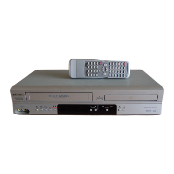
This service manual is for DV-PF35U USA model
and DV-PF35U Canada model.
For DV-PF35U Canada model, the letter
(H9851CD) is printed on rating label in the rear.
When servicing, refer to the rating label
illustration at right.
SPECIFICATIONS AND PARTS ARE SUBJECT TO CHANGE FOR IMPROVEMENT
DVD PLAYER & VIDEO CASSETTE RECORDER
April
2005
TK
DV-PF35U
Rating label
DO NOT RESELL OR DIVERT IMPROPERLY.
DO NOT RESELL OR DIVERT IMPROPERLY.
Digital Media Division,
No. 0508E
H9851CD
Yokohama
Table of Contents

Related Manuals for Hitachi DV-PF35U


Summary of Contents for Hitachi DV-PF35U
- Page 1 No. 0508E DV-PF35U SERVICE MANUAL This service manual is for DV-PF35U USA model and DV-PF35U Canada model. For DV-PF35U Canada model, the letter (H9851CD) is printed on rating label in the rear. When servicing, refer to the rating label illustration at right.
-
Page 2: Table Of Contents
CONTENTS 1 CAUTIONS FOR SAFETY IN PERFORMING 5 DISASSEMBLY ......5-1 REPAIR ....... .1-1 5-1 CABINET DISASSEMBLY INSTRUCTIONS . -
Page 3: Cautions For Safety In Performing
CAUTIONS FOR SAFETY IN PERFORMING REPAIR 1-1 LASER BEAM SAFETY PRECAUTIONS This DVD player uses a pickup that emits a laser beam. Do not look directly at the laser beam coming from the pickup or allow it to strike against your skin. -
Page 4: Important Safety Precautions
1-2 IMPORTANT SAFETY PRECAUTIONS 1-2-1 Product Safety Notice I. Also check areas surrounding repaired locations. J. Be careful that foreign objects (screws, solder Some electrical and mechanical parts have special droplets, etc.) do not remain inside the set. safety-related characteristics which are often not evi- K. -
Page 5: Safety Check After Servicing
1-2-3 Safety Check after Servicing Examine the area surrounding the repaired location for damage or deterioration. Observe that screws, parts, Chassis or Secondary Conductor and wires have been returned to their original posi- tions. Afterwards, do the following tests and confirm the specified values to verify compliance with safety Primary Circuit Terminals standards. -
Page 6: Standard Notes For Servicing
1-3 STANDARD NOTES FOR SERVICING General Note: "CBA" is an abbreviation for 1-3-4 Instructions for Handling "Circuit Board Assembly." Semi-conductors Electrostatic breakdown of the semi-conductors may 1-3-1 Circuit Board Indications occur due to a potential difference caused by electro- static charge during unpacking or repair work. a. -
Page 7: General Information
GENERAL INFORMATION 2-1 SPECIFICATIONS PRODUCT TYPE [DVD section] DVD Player with Video Cassette recorder DISCS (PLAYBACK COMPATIBILITY) DVD Video, Audio CD, CD-RW/R CONNECTIONS DVD-RW/R Front panel: FREQUENCY RESPONSE Video input One RCA connector DVD (linear sound) : 20 Hz to 22 kHz (sample rate: 48 kHz) Audio input Two RCA connectors (one left 20 Hz to 44 kHz (sample rate: 96 kHz) -
Page 8: Comparison Of Models
2-2 COMPARISON OF MODELS 2-2-1 General : Yes, ---: No, : Same as on left ITEM DV-PF35U DV-PF74U Dimensional 435(W) x 94(H) x 233(D)mm Weight 2.7 kg Tray Panel / FL Window Clear Color Front / Button Silver / Silver... -
Page 9: Dvd Section
2-2-3 DVD Section : Yes, ---: No, : Same as on left ITEM DV-PF35U DV-PF74U Drive Speed Laser DVD/VCD/SVCD/CD-DA O / --- / --- / O CD-R/CD-RW/DVD-R (Video Format) O / O / O DVD-RAM/DVD-RW (Video Format) --- / O... -
Page 10: Comparison Of Main Control Ics
2-3 COMPARISON OF MAIN CONTROL ICS : Same as on left ITEM DV-PF35U DV-PF74U MICRO CONTROLLER MN35302 (IC101) MN35202 (IC101) FLASH ROM MBM29LV160BE90TN-KE1 / MBM29LV160BM90TN (IC103) ES29LV160DB-90TG / M29W160EB70N6E- PBF / MX29LV160BBTC-90G / M29W160EB70N6 (IC103) NC7SB3157P6X / SN74LVC1G3157DCKR (IC201) OP AMP... -
Page 11: List Of Abbreviations And Terms For Dvd Player
2-4 LIST OF ABBREVIATIONS AND TERMS FOR DVD PLAYER Index Abbreviation/Term Explanation See Dolby AC3. CD-R One type of DVD standard disc, to which writing once is possible (recordable type) CD-RW One type of CD standard disc, to which writing up to 1000 times is possible Component video Used for outputs of HDTV video signal format. -
Page 12: Function Indicator Symbols
2-5 FUNCTION INDICATOR SYMBOLS Note: The following symbols will appear on the indicator panel to indicate the current mode or operation of the VCR. On-screen modes will also be momentarily displayed on the tv screen when you press the operation buttons. Defective Cause Indication When reel and capstan mechanism is not... -
Page 13: Operating Controls And Functions
DIGITAL AUTO TRACKING P R O G R E S S I V E S C A N GROUP P.SCAN REC TIMER LINE2 STOP PLAY DVD/VCR Combo DV-PF35U F.FWD STOP/EJECT PLAY REC/OTR CHANNEL OUTPUT VIDEO IN L (mono) AUDIO IN R... -
Page 14: Remote Control
LINE2 STOP PLAY F.FWD STOP/EJECT PLAY REC/OTR CHANNEL OUTPUT DVD/VCR Combo DV-PF35U VIDEO IN L (mono) AUDIO IN R • To select the VCR output mode • To activate the remote control in VCR mode • To select VCR position or... - Page 15 DVD ANALOG AUDIO OUT jacks DVD/VCR AUDIO OUT jacks AUDIO IN jacks Connect the supplied Audio Connect the supplied Audio Connect Audio cables coming ANT IN jack cables here through the Audio cable (red/white) here through from the audio out jacks of a Connect your antenna In jacks of a TV or other audio the audio In jacks of a TV or...
-
Page 16: Maintenance And Inspection
MAINTENANCE AND INSPECTION 3-1 TROUBLESHOOTING Troubleshooting is how to service for the specifying malfunction or poor parts. Detect malfunction or poor parts and service as the following charts. 3-1-1 Power Supply Section FLOW CHART NO.1 The power cannot be turned on. See FLOW CHART No.2... - Page 17 FLOW CHART NO.6 P-ON+9V is not outputted. (AL+5V is outputted normally.) Check D015, D031, C018, and their periphery, Is 12V voltage supplied to the collector of Q055? and service it if defective. Is the "L" pulse inputted to the base of Q052? Replace IC501.
- Page 18 FLOW CHART NO.12 DVD-P-ON+3.3V is not outputted. (DVD-P-ON+12V is outputted normally.) Is the "H" pulse (approximately 5V) inputted into Check R1077 and their periphery, and service it if the base of Q1011? defective. Replace Q1011. FLOW CHART NO.13 DVD-P-ON+5V is not outputted. (DVD-P-ON+12V is outputted normally.) Is the "H"...
-
Page 19: Dvd Section
3-1-2 DVD Section FLOW CHART NO.1 The key operation is not functioning. Are the contact point and the installation state of Re-install the key switches (SW2001, SW2002, the key switches (SW2001-2003) normal? SW2003) correctly or replace the poor switch. When pressing each key switches (SW2001, Check the key switches (SW2001, SW2002, SW2002, SW2003), do the voltage of each pin SW2003) and their periphery, and service it if... - Page 20 FLOW CHART NO.5 The [No Disc] indication. Replace the DVD Main CBA. No improvement can be found. Original DVD Main CBA is poor. Replace the DVD Mechanism. FLOW CHART NO.6 Both picture and sound do not operate normally. Replace the DVD Main CBA. No improvement can be found.
- Page 21 FLOW CHART NO.7 Picture does not appear normally. Set the disc on the disc tray, and playback. Replace the DVD Main CBA or the DVD Are the video signals outputted to each pin of Mechanism. CN1601 on the Main CBA? CN1601 8PIN S-Y(I/P)
- Page 22 FLOW CHART NO.8 Audio is not outputted. Set the disc on the disc tray, and playback. Replace the DVD Main CBA or the DVD Mechanism. Are the analog audio signals outputted to each pin of CN1601 on Main CBA? CN1601 13PIN AUDIO-L CN1601 15PIN AUDIO-R Check each line between each pin of CN1601 Are the analog audio signals inputted to each pin...
-
Page 23: Vcr Section
3-1-3 VCR Section FLOW CHART NO.1 The key operation is not functioning. Are the contact point and the installation state of Re-install some key switches correctly or the key switches normal? replace some key switches. Check the key switches and their periphery, and Is the control voltage normally inputted into service it if defective. - Page 24 FLOW CHART NO.3 Cassette tape can not be loaded. When loading a cassette tape, on Pin(69) of Check the line between the start sensor and IC501, does the "L" pulse switch to the "H" pulse? Pin(69) of IC501, and service it if defective. When loading a cassette tape, is the specified Replace the Capstan Motor Unit.
- Page 25 FLOW CHART NO.6 Capstan Motor does not rotate. Is 5V voltage supplied to Pin(2) of CN502? Check the P-ON+5V line and service it if detective. Is over approximately 2.6V voltage supplied to Check the line between Pin(5) of CN502 and Pin(5) of CN502? Pin(28) of IC501, and service it if detective.
- Page 26 FLOW CHART NO.10 Video E-E does not appear. 1) In the external input mode Is the Video signal inputted to Pins(28,30,32) of Check the line between the video input IC301? terminal (rear) and Pin(28) of IC301, and service it if defective. Check the line between the video input terminal (front) and Pin(30) of IC301, and service it if defective.
- Page 27 FLOW CHART NO.11 Hi-Fi E-E audio does not operate normally. Check the peripheral circuit of the front input terminal and service it if defective. Is each signal supplied to each pin of IC451 as below? L-ch R-ch Check the peripheral circuit of the rear input Front input terminal Pin(15) Pin(10)
- Page 28 FLOW CHART NO.12 Hi-Fi audio can not be recorded normally. (E-E mode is normal.) Is the REC FM signal outputted to Pin(21) of IC451? Replace IC451. Is the line between Pin(8) of CN253 and Service the line between Pin(8) of CN253 and Pin(21) of IC451.
- Page 29 FLOW CHART NO.15 Hi-Fi audio can not be playbacked normally in the linear audio mode. (E-E mode is normal.) Is the audio signal supplied to Pin(6) of IC301? Is the audio signal outputted to Pin(10) of IC301? Replace Check the line between Pin(10) of IC301 and Pin(62) of IC451, and IC301.
-
Page 30: How To Initialize The Dvd Player & Vcr
3-2 HOW TO INITIALIZE THE DVD PLAYER & VCR To put the program back at the factory-default, initialize the DVD player & VCR as the following procedure. < DVD Section > 1. Press [DVD], [1], [2], [3], [4], and [DISPLAY] but- tons on the remote control unit in that order. -
Page 31: Firmware Renewal Mode
3-3 FIRMWARE RENEWAL MODE 3-3-1 How to Update the Firmware Ver- The appearance shown in (*1) of Fig. 5 is described as follows: sion Note: Appearance State If the firmware has been changed, etc., we will use Reading... Sending files into the memory Service News, etc. -
Page 32: How To Verify The Firmware Version
10.Press [CLEAR C.RESET] button on the remote control unit. Fig. 10 appears on the screen. " ******* " differ depending on the models. MODEL : ******* Version : *.** Region : * EEPROM CLEAR : OK EEPROM CLEAR : CLEAR EXIT: POWER Fig. -
Page 33: Standard Maintenance
3-4 STANDARD MAINTENANCE 3-4-1 Service Schedule of Components This maintenance chart shows you the standard of replacement and cleaning time for each part. Because those may replace depending on environment and purpose for use, use the chart for reference. h: Hours : Cleaning I: Replace Deck... -
Page 34: Cleaning
3-4-2 Cleaning Cleaning of ACE Head Clean the head with a cotton swab. Cleaning of Video Head Procedure Clean the head with a head cleaning stick or chamois 1.Remove the top case. cloth. 2.Dip the cotton swab in 90% ethyl alcohol and clean Procedure the ACE head. -
Page 35: Adjustment
ADJUSTMENT 4-1 PREPARATION FOR SERVICING 4-1-1 How to Enter the Service Mode About Optical Sensors Caution: An optical sensor system is used for the Tape Start and End Sensors on this equipment. Carefully read and follow the instructions below. Otherwise the unit may operate erratically. -
Page 36: Fixture And Tape For Adjustment
4-2 FIXTURE AND TAPE FOR ADJUSTMENT 1. Alignment Tape (MH-1) 2. Guide Roller Adj. Screwdriver No. 7099046 No. 7099028 3. Flat Screwdriver (Purchase Locally) 4-2-1 How To Use The Fixtures And Tape Item No. Name Part No. Adjustment I Head Switching Position Alignment Tape (MH-1) 7099046 I Tape Interchangeability Alignment... -
Page 37: Electrical Adjustment Instructions
4-3 ELECTRICAL ADJUSTMENT INSTRUCTIONS NOTE: 1.Electrical adjustments are required after replacing circuit components and certain mechanical parts. It is important to do these adjustments only after Figure 1 all repairs and replacements have been com- pleted. Also, do not attempt these adjustments EXT. -
Page 38: Mechanical Alignment Procedures
4-4 MECHANICAL ALIGNMENT PROCEDURES Explanation of alignment for the tape to correctly run B. Method to place the Cassette Holder in the starts on the next page. Refer to the information below tape-loaded position without a cassette tape on this page if a tape gets stuck, for example, in the 1. -
Page 39: Tape Interchangeability Alignment
4-4-2. Tape Interchangeability Alignment Note: To do these alignment procedures, make sure that the Tracking Control Circuit is set to the preset position every time a tape is loaded or unloaded. (Refer to page 4-7, procedure 1-C, step 2.) Equipment required: Dual Trace Oscilloscope VHS Alignment Tape (MH-1) Guide Roller Adj. -
Page 40: 1-A. Preliminary/Final Checking And Alignment Of Tape Path
1-A. Preliminary/Final Checking and 3. Check to see that the tape runs without creasing at Alignment of Tape Path Take-up Guide Post [4] or without snaking between Guide Roller [3] and ACE Head. (Fig. M3 and M5) Purpose: 4. If creasing or snaking is apparent, adjust the Tilt To make sure that the tape path is well stabilized. -
Page 41: 1-C. Checking/Adjustment Of Envelope Waveform
5. To shift the CTL waveform, press “CH K” or “CH L” 4. If the envelope is as shown in Fig. M8, adjust the button on the remote control unit. Then make sure height of Guide Roller [3] (Refer to Fig. M3) so that that the maximum output position of PB FM enve- the waveform looks like the one shown in Fig. -
Page 42: 1-D. Azimuth Alignment Of Audio/Control/Erase Head
1-D. Azimuth Alignment of Audio/Con- 2. When the tape has been curled up or bent, turn trol/ Erase Head the alignment screw to adjust the height of REV Post. (Refer to Fig. M11 and M13.) Purpose: To correct the Azimuth alignment so that the Audio/ Control/Erase Head meets tape tracks properly. -
Page 43: Disassembly
DISASSEMBLY 5-1 CABINET DISASSEMBLY INSTRUCTIONS 5-1-1 Disassembly Flowchart REMOVAL This flowchart indicates the disassembly steps to gain REMOVE/*UNHOOK/ LOC. PART access to item(s) to be serviced. When reassembling, Fig. UNLOCK/RELEASE/ Note follow the steps in reverse order. Bend, route, and UNPLUG/DESOLDER dress the cables as they were originally. - Page 44 Reference Notes CAUTION 1: Locking Tabs (L-1) and (L-2) are fragile. Be careful not to break them. (S-1) [1] Top Case 1-1. Release three Locking Tabs (L-1). 1-2. Release three Locking Tabs (L-2), then remove the Front Assembly. CAUTION 2: Electrostatic breakdown of the laser diode in the optical system block may occur as a potential difference caused by electrostatic charge accumulated on cloth, human body etc, during...
- Page 45 CN401 (S-3) (S-7) CN601 (S-7) (S-3) [4] DVD Mechanism Assembly (S-3) (S-7) (S-5) (S-4) (S-8) [6] Loader Holder (S-8) [8] VCR Chassis Unit [5] Partition Plate Fig. D3 Fig. D5 (S-6) (S-6) [7] DVD Main CN301 CN201 DVD Mechanism Short the three short lands by soldering. (Either of two places.) View for A Connector...
- Page 46 Cylinder Assembly FE Head ACE Head Assembly SW512 Lead with blue stripe [9] Deck Assembly LD-SW Desolder (S-11) [12] Main CBA [9] Deck Assembly [11] Power SW CBA Cam Gear (S-9) [12] Main CBA Hole [10] DVD Shaft (S-10) Open/Close CBA Hole Desolder LD-SW...
-
Page 47: How To Eject Manualy
5-1-3 How to Eject Manualy A. DVD 1. Remove the Top Case, Front Assembly and Top Bracket. 2. Remove four Screws (S-3) in Fig. D3. Do not disconnect connectors. 3. While lifting up the DVD Mechanism, rotate the roulette in the direction of the arrow as shown below. 4. -
Page 48: Disassembly/Assembly Procedures Of Deck Mechanism
5-2 DISASSEMBLY/ASSEMBLY PROCEDURES OF DECK MECHANISM Before following the procedures described below, be sure to remove the deck assembly from the cabinet. (Refer to CABINET DISASSEMBLY INSTRUCTIONS on page 5-1.) All the following procedures, including those for adjustment and replacement of parts, should be done in Eject mode;... - Page 49 REMOVAL INSTALLATION STEP START- REMOVE/*UNHOOK/ /LOC. PART ADJUSTMENT Fig. No. UNLOCK/RELEASE/ CONDITION UNPLUG/DESOLDER [29] [25] Idler Gear DM1, DM14 [30] [29] Idler Arm DM1, DM14 *(L-11) [31] [25] BT Arm DM2, DM14 *(P-6) Loading Arm (SP) (+)Refer to Alignment [32] [25] DM2, DM14 Assembly...
-
Page 50: Top View
Top View [41] [42] [43] [46] [14] [13] [11] [15] [36] [10] [12] [35] [34] [40] [29] [30] [16] [39] [38] Fig. DM1 Bottom View [20] [33] [32] [24] [26] [27] [25] [23] [28] [22] [21] [31] Fig. DM2... - Page 51 (S-1) (S-1) (L-1) (L-3) (L-2) (S-1A) (P-1) Installation of [3] and [6] First, insert [6] diagonally in [3] as shown below. Then, install [6] in [3] while pushing (L-1) in a direction of arrow. After installing [6] in [3], confirm that pin A of [3] enters hole A of [6] properly.
- Page 52 (S-4) [46] [47] (L-14) Desolder from bottom (S-3) Lead with White Stripe View for A Belt Fig. DM7 (S-2) [11] (S-4A) (L-4) (P-3) [13] Removal of [11] [12] 1) Remove screw (S-4A). 2) Unhook spring (P-2). [10] Desolder Lead with Release (L-4) while (P-2) Red Stripe...
- Page 53 Installation of [13] and [12] (S-5) [14] (S-6) [16] [13] [15] Hook spring (P-3) up to [12] and [13], then install then to (P-3) the specified position so that [12] will be floated slightly while holding [12] and [13]. (Refer to Fig. A.) [12] Fig.
- Page 54 [22] (S-8) (C-2) (C-1) [23] (L-6) [21] (P-5) [20] Cap Belt (P-5) [28] Installation position of Cap Belt [21] Cap Belt When installing [23], install the spring (P-5) to [28] as shown in the left figure, and then install [23] while Pin on pressing the spring (P-5) to bottom...
- Page 55 Installation of [25] [25] (C-4) Position of Mode Lever when installed Pin of [35] Pin of [31] Pin of [34] (S-9) (L-10) (L-8) (C-3) [27] [28] [24] Bottom View [26] [25] (L-9) [28] Align [25] and [28] as shown. First groove on [28] First tooth on [44] [28] When reassembling [28],...
- Page 56 [36] Break belt (P-7) [34] [40] (P-8) turn [37] (L-12) turn [38] turn [44] [45] Slide [39] [35] Fig. DM17 Fig. DM15 [42] [41] [43] (L-13) Slide Plate (S-11) Fig. DM16 5-14...
-
Page 57: Alignment Procedures Of Mechanism
5-3 ALIGNMENT PROCEDURES OF MECHANISM The following procedures describe how to align the Alignment 1 individual gears and levers that make up the tape load- Loading Arm (SP) and (TU) Assembly ing/unloading mechanism. Since information about the state of the mechanism is provided to the System Install Loading Arm (SP) and (TU) Assembly so Control Circuit only through the Mode Switch, it is that their triangle marks point to each other as... -
Page 58: Explodeds Views And Parts List
EXPLODED VIEWS AND PARTS LIST 6-1 EXPLODED VIEWS 6-1-1 Cabinet Section 2L071 2L071 DVD Mechanism 2L071 2L021 [UNIT REPLACEMENT (ORDER FORMAT)] 2L021 2L071 2L021 L0-9 2L082 Sensor CBA W004 2L021 [COMPONENT 2L062 2L051 REPLACEMENT] 2B11 DVD Main CBA Main CBA [CBA REPLACEMENT (ORDER FORMAT)] [COMPONENT 2L012... -
Page 59: Deck Mechanism View 1 Section
6-1-2 Deck Mechanism View 1 Section 6-1-3 Deck Mechanism View 2 Section Mark Description Floil G-684G or Multemp MH-D Mark Description (Blue grease) Floil G-684G or Multemp MH-D (Blue grease) SLIDUS OIL #150 SLIDUS OIL #150 B587 B487 B521 SANKOUL FG84M (Yellow grease) B416 B591 B520... -
Page 60: Deck Mechanism View 3 Section
6-1-4 Deck Mechanism View 3 Section Mark Description Floil G-684G or Multemp MH-D (Blue grease) SLIDUS OIL #150 L1321 B347 L1321 B355 B354 B483 L1341 B425 B482 B562 B300 B563 B313 B529 B360 B359 B361 B555 B303 B514... -
Page 61: Replacement Parts List
6-2 REPLACEMENT PARTS LIST 6-2-1 Mechanical Parts List SYMBOL-NO P-NO DESCRIPTION SYMBOL-NO P-NO DESCRIPTION B355 TJ15103 SLIDER(SP) MK12 MECHANISM SECTION B359 TJ15103 CLEANER LEVER MK10 TJ18631 FRONT ASSEMBLY H9850UD B360 TJ14676 CLEANER ROLLER MK9 TJ18632 TOP CASE H9650UD B361 TJ15105 CL POST MK10 TJ17701 JACK BOARD(TUNER) H9600UD... - Page 62 SYMBOL-NO P-NO DESCRIPTION SYMBOL-NO P-NO DESCRIPTION B592 TJ16936 TG POST MK11 B593 TJ17691 CAM HOLDER ASSEMBLY MK12.5 L1051 TJ14055 SCREW B-TIGHT M2.6X6 PAN HEAD+ L1053 TJ14283 SCREW S-TIGHT M2.6X8 WASHER HEAD+ L1151 TJ15236 SCREW SEMS M2.6X4 PAN HEAD+ L1191 TJ14283 SCREW S-TIGHT M2.6X8 WASHER HEAD+ L1321 TJ10176...
-
Page 63: Electrical Parts List
Note: Although some parts in the schematic diagrams have different names from those in 6-2-2 Electrical Parts List the parts list, there is no problem in replacing parts. SYMBOL-NO P-NO DESCRIPTION SYMBOL-NO P-NO DESCRIPTION D1037 TC10752 RECTIFIER DIODE 1N4005 CAPACITOR D1038 TC10752 RECTIFIER DIODE 1N4005... - Page 64 SYMBOL-NO P-NO DESCRIPTION SYMBOL-NO P-NO DESCRIPTION Q565 TC10782 TRANSISTOR KTA1267(Y) SW505 TE11957 TACT SWITCH KSM0614B Q566 TC10778 TRANSISTOR KTC3199(Y) SW508 TE11957 TACT SWITCH KSM0614B Q567 TC10778 TRANSISTOR KTC3199(Y) SW509 TE11957 TACT SWITCH KSM0614B SW511 TE15484 LEAF SWITCH MXS01830MVP0 TRANSFORMER SW512 TJ17666 ROTARY MODE SWITCH SSS-53MD ! T001...
-
Page 65: Appendix
APPENDIX 7-1 SYSTEM CONTROL TIMING CHARTS [ VCR Section ] Mode SW : LD-SW LD-SW Position detection A/D Input voltage Limit Symbol (Calculated voltage) 3.76V~4.50V (4.12V) 4.51V~5.00V (5.00V) 0.00V~0.25V (0.00V) 1.06V~1.50V (1.21V) 0.66V~1.05V (0.91V) 1.99V~2.60V (2.17V) 1.51V~1.98V (1.80V) 3.20V~3.75V (3.40V) 0.26V~0.65V (0.44V) 4.51V~5.00V... - Page 66 Still/Slow Control Frame Advance Timing Chart 1) SP Mode 18 RF-SW The first rise of RF-SW after a rise in F-AD signal F-AD (Internal Signal) "H" "H" "Z" C-DRIVE "L" "L" Stop detection (T2) Acceleration Detection (T1) Slow Tracking Value PB CTL Reversal Limit Value 20ms...
- Page 67 2) LP/SLP Mode 18 RF-SW The first rise of RF-SW after a rise in F-AD signal F-AD (Internal Signal) "H" "H" "Z" C-DRIVE "L" "L" Stop detection (T2) Acceleration Detection (T1) Slow Tracking Value PB CTL Reversal Limit Value 20ms 27 C-F/R 79 H-A-SW 78 ROTA...
- Page 68 1. EJECT (POWER OFF) -> CASSETTE IN (POWER ON) -> STOP(B) -> STOP(A) -> PLAY -> RS -> FS -> PLAY -> STILL -> PLAY -> STOP(A) PIN NO. LD-SW CL/SS 0.3S 0.3S LM-FWD "M" /REV 0.2S 0.2S 0.2S 0.2S 0.2S "Z"...
- Page 69 2. STOP(A) -> FF -> STOP(A) -> REW -> STOP(A) -> REC -> PAUSE -> PAUSE or REC -> STOP(A) -> EJECT PIN NO. LD-SW CL/SS LM-FWD "M" /REV 0.2S 0.2S 0.2S 0.2S 0.2S 0.2S "Z" C-DRIVE 20mS 0.1S 20mS 20mS 0.4S 0.4S...
- Page 70 [ DVD Section ] Tray Close ~ Play / Play ~ Tray Open Tray Disc Disc Tray Play Close Rotation Stop Open 3.3V Tray IN (TL221 on the DVD Main CBA) Sled Drive 1.65V (TP303 on the DVD Main CBA) Disc Drive 1.65V (TP301 on...
-
Page 71: Ic Pin Function Descriptions
7-2 IC PIN FUNCTION DESCRIPTIONS [ VCR Section ] Signal Active Function Name Level IC501( SERVO / SYSTEM CONTROL IC ) 21 OUT LM-FWD/ Loading Motor H/Z/L FWD/ REV Output “H” ≥ 4.5V, “L” ≤ 1.0V Power On Signal to 22 OUT P-ON-L Signal Active... - Page 72 Signal Active Signal Active Function Function Name Level Name Level N.U. Not Used Tape Start Position IN ST-S Detector Signal OUTPUT- 46 OUT Output Select SELECT VCR Mode LED 70 OUT DVD-L-IND Signal Output Drum PG/FG Input IN D-PFG PULSE DVD Mode LED Signal 71 OUT DVD-H-IND...
- Page 73 IC571 [ PT6313-S-TP ] Signal In/Out Name Function Name FP-CLK Clock Input FP-STB Serial Interface Strobe N.U. Not Used N.U. Not Used Power Supply Out a Out b Out c Out d Segment Output Out e Out h Pull Down Level Out i Segment Output Grid Output...
-
Page 74: Lead Identifications
7-3 LEAD IDENTIFICATIONS 2SA1175(J,H,F) 2SK3757(Q) KIA4558P 2SA1015-GR(TPE2) 2SC2785(J,H,F,K) RC4580IP 2SK3543 2SC1815-BL(TPE2) BA1F4M-T UTC4558 2SC1815-Y(TPE2) BN1F4M-T KIA4558P/P 2SC2120-Y(TPE2) KRA103M KTC3198(Y,GR) KRC103M KTC3203(Y) KTA1266(GR) 2SC2001(K,L) KTA1267(GR,Y) KTC3193(Y) KTC3199(Y,GR,BL) G D S E C B E C B 2SC536NF-NPA-AT PT6313-S-TP EL817A MID-32A22F 2SC536NG-NPA-AT SC16313 EL817B PT204-6B-12... -
Page 75: Sschematic, Wiring Diagrams
SCHEMATIC, WIRING DIAGRAMS S-1 Schematic Diagrams / CBA’s and Test Points Standard Notes Notes: 1. Do not use the part number shown on these draw- WARNING ings for ordering. The correct part number is shown Many electrical and mechanical parts in this chassis in the parts list, and may be slightly different or have special characteristics. - Page 76 LIST OF CAUTION, NOTES, AND SYMBOLS USED IN THE SCHEMATIC DIAGRAMS ON THE FOLLOWING PAGES: 1. CAUTION: FOR CONTINUED PROTECTION AGAINST FIRE HAZARD, REPLACE ONLY WITH THE SAME TYPE FUSE. ATTENTION: POUR UNE PROTECTION CONTINUE LES RISQES D'INCELE N'UTILISER QUE DES FUSIBLE DE MEMO TYPE.
-
Page 77: S-2 Wiring Diagram < Vcr Section >
S-2 Wiring Diagrams < VCR SECTION > FRONT REAR (DECK ASSEMBLY) VIDEO AUDIO(R) AUDIO(L) S-VIDEO AUDIO(R) AUDIO(L) VIDEO AUDIO(R) AUDIO(L) VIDEO AUDIO(R) AUDIO(L) DIGITAL VIDEO VIDEO VIDEO -OUT -OUT -OUT -OUT -OUT -Pr/Cr -Pb/Cb AUDIO OUT ACE HEAD ASSEMBLY CN504 ANT-IN AUDIO AE-H... -
Page 78: S-3 Wiring Diagram < Dvd Section >
S-3 Wiring Diagrams < DVD SECTION > DVD MECHANISM CN401 EV+1.2V EV+1.2V EV+3.3V EV+3.3V EV+3.3V DVD-P-ON+3.3V DVD-P-ON+5V CN301 EV+10V TRAY-IN SP(+) EV+10V SP(-) TRAY-IN SPINDLE MOTOR SL(-) TO MAIN CBA SLED CN1001 8 SL(+) MOTOR (W001) PWRCON DRIVE CBA FP-CLK FP-DIN FP-STB FP-DOUT(NU) -
Page 79: Main 1/8 Schematic Diagram
S-4 Main 1/8 Schematic Diagram... -
Page 80: Main 2/8, Sensor & Power Sw Schematic Diagrams
S-5 Main 2/8, Sensor & Power SW Schematic Diagram FIP502 MATRIX CHART SACD REPEAT PSCAN GROUP CHP. TITLE SACD REPEAT TITLE GROUP PSCAN HD VCD... -
Page 81: Main 3/8 Schematic Diagram
S-6 Main 3/8 Schematic Diagram... -
Page 82: Main 4/8 Schematic Diagram
S-7 Main 4/8 Schematic Diagram... -
Page 83: Main 5/8 Schematic Diagram
S-8 Main 5/8 Schematic Diagram... -
Page 84: Main 6/8 & Dvd Open/Close Schematic Diagram
S-9 Main 6/8 & DVD Open/Close Schematic Diagram S-10... -
Page 85: S-11Main 8/8 Schematic Diagram
S-10 Main 7/8 Schematic Diagram CAUTION ! CAUTION ! NOTE: For continued protection against fire hazard, Fixed voltage (or Auto voltage selectable) power supply circuit is used in this unit. The voltage for parts in hot circuit is measured using replace only with the same type fuse. - Page 86 S-11 Main 8/8 Schematic Diagram S-12...
-
Page 87: S-12Dvd Main 1/3 Schematic Diagram
S-12 DVD Main 1/3 Schematic Diagram 1 NOTE: Either IC461 or IC462 is used for DVD MAIN CBA. S-13... -
Page 88: S-13Dvd Main 2/3 Schematic Diagram
S-13 DVD Main 2/3 Schematic Diagram S-14... -
Page 89: S-14Ic101 Voltage Chart
S-14 IC101 Voltage Chart ~ : Voltage is not consistent ----- : Not used Unit : Volts PIN.NO PLAY STOP PIN.NO PLAY STOP PIN.NO PLAY STOP PIN.NO PLAY STOP PIN.NO PLAY STOP PIN.NO PLAY STOP PIN.NO PLAY STOP PIN.NO PLAY STOP ----- -----... -
Page 90: S-15Dvd Main 3/3 Schematic Diagram
S-15 DVD Main 3/3 Schematic Diagram S-16... -
Page 91: S-16Waveforms
S-16 Waveforms NOTE: Input VCR: COLOR BAR SIGNAL (WITH 1KHz AUDIO SIGNAL) (WF1~WF3) DVD: POWER ON (STOP) MODE (WF4~WF6) CD: 1kHz PLAY (WF7~WF9) TP751 Pin 13 of CN1601 Pin 8 of CN1601 V-OUT E-E 0.2V 20µs AUDIO-L 0.5ms 0.5ms VIDEO-Y 0.2V 20µs TP751... -
Page 92: Ccircuit Board Diagrams
CIRCUIT BOARD DIAGRAMS C-1 Main CBA, Sensor CBA, DVD Open/Close CBA, Power SW CBA Top View DVD Open/Close CAUTION ! Because a hot chassis ground is present in the power CAUTION ! supply circut, an isolation transformer must be used. For continued protection against fire hazard, Fixed voltage (or Auto voltage selectable) power supply circuit is used in this unit. -
Page 93: Main Cba Bottom View
C-2 Main CBA Bottom View CAUTION ! CAUTION ! Because a hot chassis ground is present in the power Fixed voltage (or Auto voltage selectable) power supply circuit is used in this unit. For continued protection against fire hazard, supply circut, an isolation transformer must be used. If Main Fuse (F1001) is blown , check to see that all components in the power supply replace only with the same type fuse. -
Page 94: Bblock Diagrams
BLOCK DIAGRAMS B-1 Servo / System Control Block Diagram... -
Page 95: Video Block Diagram
B-2 Video Block Diagram... -
Page 96: Audio Block Diagram
B-3 Audio Block Diagram... -
Page 97: Hi-Fi Audio Block Diagram
B-4 Hi-Fi Audio Block Diagram... -
Page 98: Power Supply Block Diagram
B-5 Power Supply Block Diagram... -
Page 99: Dvd System Control/Servo Block Diagram
B-6 DVD System Control / Servo Block Diagram... -
Page 100: Digital Signal Process Block Diagram
B-7 Digital Signal Process Block Diagram... -
Page 101: Dvd Video / Audio Block Diagram
B-8 DVD Video / Audio Block Diagram... - Page 102 No. 0508E Digital Media Division, Yokohama DV-PF35U...