
Related Manuals for Nokia RH-64


Summary of Contents for Nokia RH-64
- Page 1 Nokia Customer Care Service Manual RH-64 (Nokia 1600) Mobile Terminal Part No: (9243363 (Issue 1)) Company Confidential Copyright ©2005 Nokia. All Rights Reserved.
- Page 2 RH-64 Nokia Customer Care Amendment Record Sheet Amendment Record Sheet Amendment No Date Inserted By Comments Original issue 07/2005 G Rudh Page ii Company Confidential 9243363 (Issue 1) Copyright ©2005 Nokia. All Rights Reserved.
- Page 3 Nokia operates a policy of continuous development. Nokia reserves the right to make changes and improvements to any of the products described in this document without prior notice. Under no circumstances shall Nokia be responsible for any loss of data or income or any special, incidental, consequential or indirect damages howsoever caused.
- Page 4 WCDMA networks and cause problems to 3G cellular phone communication in a wide area. • During testing never activate the GSM or WCDMA transmitter without a proper antenna load, otherwise GSM or WCDMA PA may be damaged. Page iv Company Confidential 9243363 (Issue 1) Copyright ©2005 Nokia. All Rights Reserved.
- Page 5 Use only approved accessories and batteries. Do not connect incompatible products. CONNECTING TO OTHER DEVICES When connecting to any other device, read its user’s guide for detailed safety instructions. Do not connect incompatible products. 9243363 (Issue 1) Company Confidential Page v Copyright ©2005 Nokia. All Rights Reserved.
- Page 6 All of the above suggestions apply equally to the product, battery, charger or any accessory. Page vi Company Confidential 9243363 (Issue 1) Copyright ©2005 Nokia. All Rights Reserved.
- Page 7 Nokia Customer Care ESD protection Nokia requires that service points have sufficient ESD protection (against static electricity) when servicing the phone. Any product of which the covers are removed must be handled with ESD protection. The SIM card can be replaced without ESD protection if the product is otherwise ready for use.
-
Page 8: Battery Information
Do not dispose of batteries in a fire! Dispose of batteries according to local regulations (e.g. recycling). Do not dispose as household waste. Page viii Company Confidential 9243363 (Issue 1) Copyright ©2005 Nokia. All Rights Reserved. - Page 9 While every endeavour has been made to ensure the accuracy of this document, some errors may exist. If any errors are found by the reader, NOKIA MOBILE PHONES Business Group should be notified in writing/e-mail. Please state: • Title of the Document + Issue Number/Date of publication •...
- Page 10 RH-64 Nokia Customer Care Company Policy (This page left intentionally blank.) Page x Company Confidential 9243363 (Issue 1) Copyright ©2005 Nokia. All Rights Reserved.
- Page 11 2 Parts and layouts 3 Phoenix service software 4 Service tools and concepts 5 Disassembly and reassembly instructions 6 Baseband troubleshooting 7 RF troubleshooting 8 System module 9 Schematics 9243363 (Issue 1) Company Confidential Page xi Copyright ©2005 Nokia. All Rights Reserved.
- Page 12 RH-64 Nokia Customer Care Nokia 1600 Service Manual Structure (This page left intentionally blank.) Page xii Company Confidential 9243363 (Issue 1) Copyright ©2005 Nokia. All Rights Reserved.
- Page 13 Nokia Customer Care 1 — General information 9243363 (Issue 1) Company Confidential Page 1–1 Copyright ©2005 Nokia. All Rights Reserved.
- Page 14 RH-64 Nokia Customer Care General information (This page left intentionally blank.) Page 1–2 Company Confidential 9243363 (Issue 1) Copyright ©2005 Nokia. All Rights Reserved.
-
Page 15: Table Of Contents
Table 2 Car......................................1–7 Table 3 Audio....................................1–7 Table 4 Xpress-on™ covers................................1–7 Table 5 Normal and extreme voltages.............................1–8 Table 6 Current consumption..............................1–9 List of Figures Figure 1 RH-64 product picture..............................1–5 9243363 (Issue 1) Company Confidential Page 1–3 Copyright ©2005 Nokia. All Rights Reserved. - Page 16 RH-64 Nokia Customer Care General information (This page left intentionally blank.) Page 1–4 Company Confidential 9243363 (Issue 1) Copyright ©2005 Nokia. All Rights Reserved.
-
Page 17: Product Selection
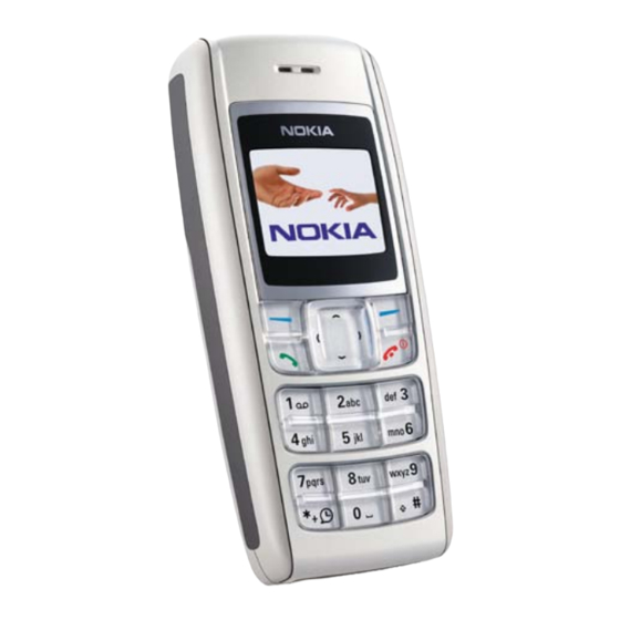
General information Nokia Customer Care Product selection The RH-64 has a dual band transceiver unit designed for the GSM900 and GSM1800 networks. Figure 1 RH-64 product picture Display and keypad features • High resolution CSTN display (96x68 pixels) with 65,536 colors •... -
Page 18: Ui Features
• Phone Features • Alarm clock Calendar Mobile enhancements Table 1 Power Type Name BL-5C Battery 900 mAh Li-Ion AC-1 Retractable charger ACP-12 Travel charger LCH-12 Mobile charger Page 1–6 Company Confidential 9243363 (Issue 1) Copyright ©2005 Nokia. All Rights Reserved. -
Page 19: Technical Specifications
Weight (g) Volume (cc) Transceiver with BL-5C 104x44.7x17.2 900mAh Li-Ion battery pack Battery endurance Nokia measurements of operation times in GSM900/1800 Talk time Battery: BL-5C 900mAh Up to 180 min Standby time Battery: BL-5C 900mAh Up to 300 min Note: Variation in operation times will occur depending on SIM card, network settings and usage. -
Page 20: Environmental Conditions
In call SW shutdown 3. 2V In idle Min operating voltage Vcoff+ 3. 1V ± 0,1V Off to on Vcoff- 2. 8V ± 0,1V On to off Page 1–8 Company Confidential 9243363 (Issue 1) Copyright ©2005 Nokia. All Rights Reserved. -
Page 21: Table 6 Current Consumption
The minimum battery cell voltage required for the reset circuitry to turn on. This is not confirmed by measures at pt. Table 6 Current consumption Condition Typical Unit Call (MoU) (E)GSM 900 GSM 1800 GSM 1900 Idle (MoU) 2.72 Power off 9243363 (Issue 1) Company Confidential Page 1–9 Copyright ©2005 Nokia. All Rights Reserved. - Page 22 RH-64 Nokia Customer Care General information (This page left intentionally blank.) Page 1–10 Company Confidential 9243363 (Issue 1) Copyright ©2005 Nokia. All Rights Reserved.
-
Page 23: Issue 1) Company Confidential Page
Nokia Customer Care 2 — Parts and layouts 9243363 (Issue 1) Company Confidential Page 2–1 Copyright ©2005 Nokia. All Rights Reserved. - Page 24 RH-64 Nokia Customer Care Parts and layouts (This page left intentionally blank.) Page 2–2 Company Confidential 9243363 (Issue 1) Copyright ©2005 Nokia. All Rights Reserved.
-
Page 25: Table Of Contents
SWAP phones....................................2–8 Component parts list..................................2–8 Component layouts..................................2–15 List of Tables Table 7 Mechanical parts list...............................2–6 Table 8 SWAP phones for RH-64..............................2–8 Table 9 Component parts list..............................2–8 List of Figures Figure 2 Exploded view.................................2–5 Figure 3 Spare parts overview..............................2–7 Figure 4 Component layout, bottom side (1jv_50e)......................2–15 Figure 5 Component layout, top side (1jv_50e)........................2–15... - Page 26 RH-64 Nokia Customer Care Parts and layouts (This page left intentionally blank.) Page 2–4 Company Confidential 9243363 (Issue 1) Copyright ©2005 Nokia. All Rights Reserved.
-
Page 27: Exploded View
RH-64 Parts and layouts Nokia Customer Care Exploded view Figure 2 Exploded view 9243363 (Issue 1) Company Confidential Page 2–5 Copyright ©2005 Nokia. All Rights Reserved. -
Page 28: Mechanical Parts List
I015* Release button I016* SIM lid (A2) I017 Microphone I018 Easy flash connector (A2) I019* D-cover (A2) I020 Type label I021 B-cover I022 Easy flash connector cap Page 2–6 Company Confidential 9243363 (Issue 1) Copyright ©2005 Nokia. All Rights Reserved. -
Page 29: Spare Parts Overview
RH-64 Parts and layouts Nokia Customer Care Spare parts overview Figure 3 Spare parts overview 9243363 (Issue 1) Company Confidential Page 2–7 Copyright ©2005 Nokia. All Rights Reserved. -
Page 30: Swap Phones
RH-64 Nokia Customer Care Parts and layouts SWAP phones Table 8 SWAP phones for RH-64 SWAP phones for RH-64 RH-64 SWAP ENGINE EURO-C RH-64 SWAP ENGINE EURO-C FRANCE RH-64 EURO-C TURKEY RH-64 SWAP ENGINE EURO-K RH-64 SWAP ENGINE UKR RH-64 SWAP ENGINE EURO-L SOUTH AFRICA... - Page 31 100n C2239 CHIPCAP X5R 100N K 10V 0402 100n C2240 Chipcap X7R 10% 16V 0402 C2241 Chipcap X7R 10% 50V 0402 C2242 Chipcap X7R 10% 50V 0402 9243363 (Issue 1) Company Confidential Page 2–9 Copyright ©2005 Nokia. All Rights Reserved.
- Page 32 C7620 CHIPCAP X5R 2U2 K 6V3 0603 C7623 Chipcap 5% NP0 C7624 CHIPCAP X5R 100N K 10V 0402 100n C7625 Chipcap 5% NP0 C7627 Chipcap 5% NP0 Page 2–10 Company Confidential 9243363 (Issue 1) Copyright ©2005 Nokia. All Rights Reserved.
- Page 33 Chipcap 5% NP0 C7728 CHIPCAP NP0 0P5 C 50V 0402 D2200 UEMCLITE V2.2 WD ENA LEADFREE TFBGA120 D2800 UPP2M V2 10X10 D3000 FLASH 2MX16 1.8/1.8V VFBGA44 PBFREE 2Mx16 9243363 (Issue 1) Company Confidential Page 2–11 Copyright ©2005 Nokia. All Rights Reserved.
- Page 34 R2008 CHIP VARISTOR VWM14V VC50V 0402 14V/50V R2009 CHIP VARISTOR VWM14V VC50V 0402 14V/50V R2010 Resistor 5% 63mW 100k R2011 RES NETWORK 0W06 2X10R J 0404 2x10R Page 2–12 Company Confidential 9243363 (Issue 1) Copyright ©2005 Nokia. All Rights Reserved.
- Page 35 ASIP SIM INTERFACE **LOW CAP**BGA8 R2900 Resistor 5% 63mW 330R R3030 Resistor 5% 63mW R7605 Resistor 5% 63mW R7606 Chipres 0W06 jumper 0402 R7609 Resistor 1% 63mW 9243363 (Issue 1) Company Confidential Page 2–13 Copyright ©2005 Nokia. All Rights Reserved.
- Page 36 SM LYNX BATT.CONN 3POL 12V 2A H7 X2060 Bottom MODULE ID COMPONENT 2.8X1.8X0.3 X2700 SM SIM CONN 6POL P2.54 H1.8 Z2400 ASIP EMIF10-1K010F2 **PB-FREE** Z7600 SAW FILT 1842,5+-37.5MHZ 2.0X1.6 1842.5MHz Page 2–14 Company Confidential 9243363 (Issue 1) Copyright ©2005 Nokia. All Rights Reserved.
-
Page 37: Component Layouts
SILICON FILT 1810+-100MHZ P-TSLP-7-4 1710-1910MHz Component layouts Component layout, bottom side Figure 4 Component layout, bottom side (1jv_50e) Component layout, top side Figure 5 Component layout, top side (1jv_50e) 9243363 (Issue 1) Company Confidential Page 2–15 Copyright ©2005 Nokia. All Rights Reserved. - Page 38 RH-64 Nokia Customer Care Parts and layouts (This page left intentionally blank.) Page 2–16 Company Confidential 9243363 (Issue 1) Copyright ©2005 Nokia. All Rights Reserved.
- Page 39 Nokia Customer Care 3 — Phoenix service software 9243363 (Issue 1) Company Confidential Page 3–1 Copyright ©2005 Nokia. All Rights Reserved.
- Page 40 RH-64 Nokia Customer Care Phoenix service software (This page left intentionally blank.) Page 3–2 Company Confidential 9243363 (Issue 1) Copyright ©2005 Nokia. All Rights Reserved.
- Page 41 Figure 29 Data package installation status..........................3–19 Figure 30 Finish data package installation..........................3–19 Figure 31 Uninstalling Phoenix data package........................3–20 Figure 32 Finish data package uninstallation........................3–20 Figure 33 Login....................................3–21 9243363 (Issue 1) Company Confidential Page 3–3 Copyright ©2005 Nokia. All Rights Reserved.
- Page 42 Figure 68 Finish JBV-1 update installation...........................3–36 Figure 69 Checking JBV-1 SW version.............................3–36 Figure 70 JBV-1 update directory window...........................3–37 Figure 71 JBV-1 SW update done.............................3–37 Figure 72 JBV-1 SW status................................3–37 Page 3–4 Company Confidential 9243363 (Issue 1) Copyright ©2005 Nokia. All Rights Reserved.
-
Page 43: Introduction
• Minimum: Processor 300 MHz, RAM memory 64 MB, disk space 100 MB. • Recommended for Windows 2000: Processor 700 MHz, RAM memory 256 MB, disk space 150 MB. 9243363 (Issue 1) Company Confidential Page 3–5 Copyright ©2005 Nokia. All Rights Reserved. -
Page 44: Installing Phoenix
For more detailed information, please refer to Phoenix Help files. Each feature in Phoenix has its own Help function, which can be activated while running the program. Press the F1 key or the Help button to activate a Help file. Page 3–6 Company Confidential 9243363 (Issue 1) Copyright ©2005 Nokia. All Rights Reserved. - Page 45 1. Run the phoenix_service_sw_a15_2004_24_7_55.exe to start installation. Install Shield prepared the setup. Figure 7 Preparing setup Install Shield will prepare. 2. Click Next in Welcome dialog to continue. Figure 8 Welcome dialog 9243363 (Issue 1) Company Confidential Page 3–7 Copyright ©2005 Nokia. All Rights Reserved.
- Page 46 Phoenix service software 3. Read the disclaimer carefully. Figure 9 Disclaimer text 4. Choose destination folder. The default folder C:\ProgramFiles\Nokia\Phoenix is recommended. Then click Next to continue. You may choose another location by selecting Browse (not recommended). Figure 10 Destination folder Page 3–8...
- Page 47 The process may take several minutes to complete. If the operating system does not require rebooting (Windows 2000, XP) the PC components are registered right away. Figure 12 Installation status 2 9243363 (Issue 1) Company Confidential Page 3–9 Copyright ©2005 Nokia. All Rights Reserved.
- Page 48 Figure 14 Restart computer After the reboot, components are registered and Phoenix is ready for use. Note: Phoenix does not work, if components have not been registered. Page 3–10 Company Confidential 9243363 (Issue 1) Copyright ©2005 Nokia. All Rights Reserved.
-
Page 49: Phoenix Update Installation
• Close all other programs. • Run the application file (for example, phoenix_service_sw_a15_2004_24_7_55.exe). • New version of Phoenix will be installed. • Driver versions will be checked and updated. 9243363 (Issue 1) Company Confidential Page 3–11 Copyright ©2005 Nokia. All Rights Reserved. -
Page 50: Uninstalling Phoenix
Uninstallation can be done manually from Windows Control Panel → Add/Remove Programs . Steps 1. Choose Phoenix Service Software → Add/Remove → Remove to uninstall Phoenix. Figure 18 Remove program The progress of the uninstallation is shown. Page 3–12 Company Confidential 9243363 (Issue 1) Copyright ©2005 Nokia. All Rights Reserved. - Page 51 Else, Install Shield Wizard will tell you about it. Select Yes... to reboot the PC immediately and No... to reboot the PC manually afterwards. Figure 20 Finish uninstallation 9243363 (Issue 1) Company Confidential Page 3–13 Copyright ©2005 Nokia. All Rights Reserved.
-
Page 52: Repairing Phoenix Installation
2. Select Phoenix Service Software → Add/Remove . 3. In the following view, choose Repair. Phoenix will now reinstall components and register them. The procedure is the same as in the update installation. Page 3–14 Company Confidential 9243363 (Issue 1) Copyright ©2005 Nokia. All Rights Reserved. -
Page 53: Phoenix Service Software Data Package Overview
• Files for type label printing • Validation file for the faultlog repair data reporting system • All product-specific configuration files for Phoenix Service Software components Data files are stored under C:\Program Files\Nokia\Phoenix (default). 9243363 (Issue 1) Company Confidential Page 3–15... -
Page 54: Installing Phoenix Data Package
1. To start installation, run the application file (for example, RM-51_dp_EA_ v_1_0.exe). 2. Click Next, and wait for the installation files to be extracted. Figure 24 Extracting files Page 3–16 Company Confidential 9243363 (Issue 1) Copyright ©2005 Nokia. All Rights Reserved. - Page 55 In this view you can see the contents of the data package. Read the text carefully. There should be information about the Phoenix version required with this data package. Click Next to continue. Figure 26 Data package setup information 9243363 (Issue 1) Company Confidential Page 3–17 Copyright ©2005 Nokia. All Rights Reserved.
- Page 56 The install shield checks where the Phoenix application is installed and the directory is shown. Click Next to continue. 5. Click Next to start copying the files. Phone model specific files will be installed. Please wait. Figure 28 Start copying files Page 3–18 Company Confidential 9243363 (Issue 1) Copyright ©2005 Nokia. All Rights Reserved.
- Page 57 Phoenix can be used, for example, for flashing phones and printing type labels. But first you must: • configure users, and • manage connections. FLS-4S can be used right away. FPS-8* can be used after updating Flash Update Package files. 9243363 (Issue 1) Company Confidential Page 3–19 Copyright ©2005 Nokia. All Rights Reserved.
-
Page 58: Uninstalling Phoenix Data Package
• Uninstallation can also be done manually from Windows Control Panel → Add/Remove Programs → xx-xx (* Phone Data Package) . (*= type designator of the phone Next action Run the installation package again to continue installation from the beginning. Page 3–20 Company Confidential 9243363 (Issue 1) Copyright ©2005 Nokia. All Rights Reserved. -
Page 59: Service Software Instructions
Figure 35 Add information for new user 2 A new user is now created. 4. Click OK. You are now able to login with this user name. 9243363 (Issue 1) Company Confidential Page 3–21 Copyright ©2005 Nokia. All Rights Reserved. -
Page 60: Managing Connections In Phoenix
Figure 37 Phoenix icon 2. Choose File → Manage Connections . Figure 38 Manage connections Existing connections can be selected, edited, deleted, and new ones created by using this dialog. Page 3–22 Company Confidential 9243363 (Issue 1) Copyright ©2005 Nokia. All Rights Reserved. - Page 61 • COM Port: Virtual COM Port used by FLS-4 Note: ALWAYS check this. Go to Windows → Control Panel → FLS Virtual Port → Configuration . Figure 41 FLS virtual port icon 9243363 (Issue 1) Company Confidential Page 3–23 Copyright ©2005 Nokia. All Rights Reserved.
- Page 62 When a product is found, Phoenix will load product support. Name of the loaded product support module and its version information will be shown on the bottom of the screen. Page 3–24 Company Confidential 9243363 (Issue 1) Copyright ©2005 Nokia. All Rights Reserved.
-
Page 63: Installing Flash Support Files For Fps-8* And Fls-4
SW update (Page 3–28) after installing a new phone data package. Steps 1. Start by double clicking flash_update_03_13_001.exe to begin installation. Figure 46 Flash update welcome dialog 9243363 (Issue 1) Company Confidential Page 3–25 Copyright ©2005 Nokia. All Rights Reserved. - Page 64 Figure 48 Flash installation interrupted If an older version exists on your PC and it needs to be updated, click Next to continue installation. Figure 49 Continue flash update Page 3–26 Company Confidential 9243363 (Issue 1) Copyright ©2005 Nokia. All Rights Reserved.
- Page 65 RH-64 Phoenix service software Nokia Customer Care 3. It is highly recommended to install the files to the default destination folder C:\Program Files\Nokia \Phoenix. Click Next to continue. Figure 50 Flash destination folder When installing the flash update files for the first time you may choose another location by selecting Browse.
-
Page 66: Updating Fps-8 Flash Prommer Software
2. Choose Flashing → FPS-8 Maintenance . Figure 54 FPS-8 maintenance Note: Screen shots may be different depending on the Phoenix version used and the connected components. Page 3–28 Company Confidential 9243363 (Issue 1) Copyright ©2005 Nokia. All Rights Reserved. - Page 67 4. Wait until you are notified that update has been successful; the procedure will take a couple of minutes. Click OK to close the FPS-8 Maintenance window. Figure 56 Prommer SW update done View after successful prommer software update: 9243363 (Issue 1) Company Confidential Page 3–29 Copyright ©2005 Nokia. All Rights Reserved.
-
Page 68: Activating Fps-8
Before FPS-8 can be successfully used for phone programming, it must first be activated. Fill in first the FPS-8 activation request sheet in the FPS-8 sales package and follow the instructions on the sheet (included in sales package CD-ROM or from partner web site). Page 3–30 Company Confidential 9243363 (Issue 1) Copyright ©2005 Nokia. All Rights Reserved. - Page 69 RH-64 Phoenix service software Nokia Customer Care When activation file is received (for example, 00000.in), copy it to C:\ProgramFiles\Nokia\Phoenix \BoxActivation directory on your computer (this directory is created when Phoenix is installed). Steps 1. Start Phoenix Service Software. 2. Select Flashing → FPS-8 maintenance .
-
Page 70: Deactivating Fps-8
3. In the Prommer Maintenance window, click Deactivate. 4. To confirm the deactivation, click Yes. Figure 62 Deactivation warning The box is deactivated. 5. To complete the deactivation, restart FPS-8. Page 3–32 Company Confidential 9243363 (Issue 1) Copyright ©2005 Nokia. All Rights Reserved. -
Page 71: Updating Jbv-1 Docking Station Software
Note: DO NOT CONNECT THE USB CABLE/JBV-1 TO YOUR COMPUTER YET! Figure 63 Extracting JBV-1 update files Files needed for JBV-1 package setup program will be extracted. 9243363 (Issue 1) Company Confidential Page 3–33 Copyright ©2005 Nokia. All Rights Reserved. - Page 72 Accept the suggested destination folder for installing the JBV-1 SW Package, and click Next to continue. Figure 65 JBV-1 update destination folder Select Full installation and click Next to continue. Page 3–34 Company Confidential 9243363 (Issue 1) Copyright ©2005 Nokia. All Rights Reserved.
- Page 73 Nokia Customer Care Figure 66 Select installation: Full A program folder is created and the software files are installed there. Click Next to continue. Figure 67 Select program folder 9243363 (Issue 1) Company Confidential Page 3–35 Copyright ©2005 Nokia. All Rights Reserved.
- Page 74 • If there is a previously installed JBV-1 Firmware update package (v.17 or older) on your computer, please update the JBV-1 USB driver. Please see the readme.txt file in C:\Program Files\Nokia\JBV-1 Firmware Update\JBV-1USB driver folder for instructions on how to update the JBV-1 USB Driver.
- Page 75 First, click Refresh Status to see the current SW version and then Update Firmware to update the software. After you have updated all docking stations, close the JBV-1 Firmware Update dialog box. 9243363 (Issue 1) Company Confidential Page 3–37 Copyright ©2005 Nokia. All Rights Reserved.
- Page 76 RH-64 Nokia Customer Care Phoenix service software (This page left intentionally blank.) Page 3–38 Company Confidential 9243363 (Issue 1) Copyright ©2005 Nokia. All Rights Reserved.
- Page 77 Nokia Customer Care 4 — Service tools and concepts 9243363 (Issue 1) Company Confidential Page 4–1 Copyright ©2005 Nokia. All Rights Reserved.
- Page 78 RH-64 Nokia Customer Care Service tools and concepts (This page left intentionally blank.) Page 4–2 Company Confidential 9243363 (Issue 1) Copyright ©2005 Nokia. All Rights Reserved.
-
Page 79: List Of Figures
Module jig (MJ-59) service concept...........................4–20 List of Figures Figure 73 POS flash concept..............................4–14 Figure 74 FPS-8 Prommer box flash concept........................4–15 Figure 75 FPS-10 Prommer box flash concept........................4–16 9243363 (Issue 1) Company Confidential Page 4–3 Copyright ©2005 Nokia. All Rights Reserved. - Page 80 Service tools and concepts Figure 76 FPS-11 Prommer box flash concept........................4–16 Figure 77 JBV-1 flash concept with FPS-10...........................4–16 Figure 78 JBV-1 flash concept..............................4–16 Figure 79 Module jig service concept.............................4–20 Page 4–4 Company Confidential 9243363 (Issue 1) Copyright ©2005 Nokia. All Rights Reserved.
- Page 81 The CA-28DS service cable is used to connect FLS-4S to the POS flash adapter for supplying a controlled operating voltage and data connection. Note: Old XCS-1 cable can be used as well. 9243363 (Issue 1) Company Confidential Page 4–5 Copyright ©2005 Nokia. All Rights Reserved.
- Page 82 DC cable The DC cable CA-5S is used to connect JBV-1 to the phone charger jack for ADC/VCHAR/ICHAR calibration Note: Old SCB-3 can be used as well. Page 4–6 Company Confidential 9243363 (Issue 1) Copyright ©2005 Nokia. All Rights Reserved.
- Page 83 The MBUS cable DAU-9S has a modular connector and is used, for example, between the PC's serial port and module jigs, flash adapters or docking station adapters. Note: Docking station adapters valid for DCT4 products. 9243363 (Issue 1) Company Confidential Page 4–7 Copyright ©2005 Nokia. All Rights Reserved.
- Page 84 • LAN to FBUS/Flashbus and USB conversion • Vusb output switchable by PC command FPS-10 sales package includes: • FPS-10 prommer • Power Supply with 5 country specific cords • USB cable Page 4–8 Company Confidential 9243363 (Issue 1) Copyright ©2005 Nokia. All Rights Reserved.
- Page 85 • BTEMP and BSI calibration resistor • signal from FBUS to the phone via the parallel jig • control via FBUS or USB • Flash OK/FAIL indication 9243363 (Issue 1) Company Confidential Page 4–9 Copyright ©2005 Nokia. All Rights Reserved.
- Page 86 Printer or any such device can be connected to the PC through the device if needed. RJ-51 PA Rework jig To be used with ST-30! RJ-72 Rework jig To be used with rework stencil ST-32. Page 4–10 Company Confidential 9243363 (Issue 1) Copyright ©2005 Nokia. All Rights Reserved.
- Page 87 For RF attenuation values, please refer to the Service bulletin. SF-10 POS flash adapter The POS flash adapter SF-10 allows FBUS/MBUS connections for flashing. SPS-1 Soldering Paste Spreader SRT-6 Opening tool 9243363 (Issue 1) Company Confidential Page 4–11 Copyright ©2005 Nokia. All Rights Reserved.
- Page 88 SX-4 is a BB5 security device used to protect critical features in tuning and testing. SX-4 is also needed together with FPS-10 when DCT-4 phones are flashed. Page 4–12 Company Confidential 9243363 (Issue 1) Copyright ©2005 Nokia. All Rights Reserved.
- Page 89 The RF cable is used to connect, for example, a module repair jig to the RF measurement equipment. SMA to N-Connector ca. 610mm. Attenuation for: • GSM850/900: 0.3+-0.1 dB • GSM1800/1900: 0.5+-0.1 dB • WLAN: 0.6+-0.1dB 9243363 (Issue 1) Company Confidential Page 4–13 Copyright ©2005 Nokia. All Rights Reserved.
- Page 90 POS (Point of Sales) flash concept Figure 73 POS flash concept Item Description Type Phone Battery Easy flash cable CA-65DS FLS-4S sales pack FLS-4S AC charger ACF-8 PC with Service SW CD-ROM Page 4–14 Company Confidential 9243363 (Issue 1) Copyright ©2005 Nokia. All Rights Reserved.
- Page 91 ACF-8 RS-232 (D9 – D9) cable, included in FPS-8 sales pack AXS-4 Printer cable, included in FPS-8 sales package Software protection key PKD-1 PC with service SW 9243363 (Issue 1) Company Confidential Page 4–15 Copyright ©2005 Nokia. All Rights Reserved.
- Page 92 Flash prommer box sales pack FPS-10 Power supply, included in FPS-10 sales package AFC-8 USB A to B cable CA-31D Software protection key PKD-1 Service SW (PHOENIX) Page 4–16 Company Confidential 9243363 (Issue 1) Copyright ©2005 Nokia. All Rights Reserved.
- Page 93 CA-65DS Flash prommer box sales pack FPS-11 Power supply, included in FPS-11 sales package USB A to B cable CA-31D Software protection key PKD-1 Service SW (PHOENIX) 9243363 (Issue 1) Company Confidential Page 4–17 Copyright ©2005 Nokia. All Rights Reserved.
- Page 94 Flash prommer box sales pack FPS-10 Power supply, included in FPS-10 sales package AFC-8 USB A to B cable CA-31D Software protection key PKD-1 Service SW (PHOENIX) Page 4–18 Company Confidential 9243363 (Issue 1) Copyright ©2005 Nokia. All Rights Reserved.
- Page 95 Power supply, included in FPS-8 sales package AFC-8 RS-232 (D9 – D9) cable, included in FPS-8 sales package AXS-4 Printer cable, included in FPS-8 sales package Software protection key PKD-1 Service SW (PHOENIX) 9243363 (Issue 1) Company Confidential Page 4–19 Copyright ©2005 Nokia. All Rights Reserved.
- Page 96 Item Description Type Module jig MJ-59 RF test cable XCF-4 Service MBUS/FBUS cable DAU-9S DC power cable PCS-1 Software protection key PKD-1 PC with Service SW (PHOENIX) Page 4–20 Company Confidential 9243363 (Issue 1) Copyright ©2005 Nokia. All Rights Reserved.
- Page 97 Nokia Customer Care 5 — Disassembly and reassembly instructions 9243363 (Issue 1) Company Confidential Page 5–1 Copyright ©2005 Nokia. All Rights Reserved.
- Page 98 RH-64 Nokia Customer Care Disassembly and reassembly instructions (This page left intentionally blank.) Page 5–2 Company Confidential 9243363 (Issue 1) Copyright ©2005 Nokia. All Rights Reserved.
- Page 99 RH-64 Disassembly and reassembly instructions Nokia Customer Care Table of Contents Disassembly instructions................................5–5 Reassembly instructions................................5–9 9243363 (Issue 1) Company Confidential Page 5–3 Copyright ©2005 Nokia. All Rights Reserved.
- Page 100 RH-64 Nokia Customer Care Disassembly and reassembly instructions (This page left intentionally blank.) Page 5–4 Company Confidential 9243363 (Issue 1) Copyright ©2005 Nokia. All Rights Reserved.
- Page 101 Tools needed for disassembly and reassembly. Protect the window with a film. Press the release button and remove the B-cover. Use the STR-6 to unlock the A-cover on both sides. 9243363 (Issue 1) Company Confidential Page 5–5 Copyright ©2005 Nokia. All Rights Reserved.
- Page 102 Torx Plus size 6 driver with a torque setting of 24 Ncm. Note: For reassembly, ALWAYS USE NEW SCREWS! Lift the LCD shielding while carefully pressing on the LCD module with a clean cloth. Page 5–6 Company Confidential 9243363 (Issue 1) Copyright ©2005 Nokia. All Rights Reserved.
- Page 103 Remove the LCD shielding. 10. Remove the acoustic channel. 11. Protect the LCD module with a film. 12. Take care of the surrounding components when opening the LCD connector. 9243363 (Issue 1) Company Confidential Page 5–7 Copyright ©2005 Nokia. All Rights Reserved.
- Page 104 14. Remove the LCD module. 15. Remove the light guide assembly. 16. Lift the engine module a bit with the SRT-6 and remove it from the D-cover assembly. Page 5–8 Company Confidential 9243363 (Issue 1) Copyright ©2005 Nokia. All Rights Reserved.
- Page 105 19. Remove the microphone with the slotted screwdriver. Reassembly instructions For reassembly, follow the instructions for disassembly, but in reversed order. Note: Pay extra attention to steps 7 and 5. 9243363 (Issue 1) Company Confidential Page 5–9 Copyright ©2005 Nokia. All Rights Reserved.
- Page 106 RH-64 Nokia Customer Care Disassembly and reassembly instructions (This page left intentionally blank.) Page 5–10 Company Confidential 9243363 (Issue 1) Copyright ©2005 Nokia. All Rights Reserved.
-
Page 107: Troubleshooting
Nokia Customer Care 6 — Baseband troubleshooting 9243363 (Issue 1) Company Confidential Page 6–1 Copyright ©2005 Nokia. All Rights Reserved. - Page 108 RH-64 Nokia Customer Care Baseband troubleshooting (This page left intentionally blank.) Page 6–2 Company Confidential 9243363 (Issue 1) Copyright ©2005 Nokia. All Rights Reserved.
- Page 109 Figure 97 Checking IHF and ring tone by using "Buzzer"....................6–20 Figure 98 Checking vibra function by using vibra control....................6–20 Figure 99 Earpiece fault flow chart............................6–21 Figure 100 IHF/ringing tone fault flow chart........................6–22 9243363 (Issue 1) Company Confidential Page 6–3 Copyright ©2005 Nokia. All Rights Reserved.
- Page 110 RH-64 Nokia Customer Care Baseband troubleshooting Figure 101 Headset earpiece fault flow chart........................6–23 Figure 102 Microphone fault flow chart..........................6–24 Figure 103 Headset microphone fault flow chart......................6–25 Page 6–4 Company Confidential 9243363 (Issue 1) Copyright ©2005 Nokia. All Rights Reserved.
-
Page 111: General Baseband Troubleshooting
This means that the phone does not use any current at all when the supply is connected and/or power key is pressed. It is assumed that the voltage supplied is 3.6VDC. The UEMCLite will prevent any functionality at battery/ supply levels below 2.9VDC. 9243363 (Issue 1) Company Confidential Page 6–5 Copyright ©2005 Nokia. All Rights Reserved. -
Page 112: Flash Programming Do Not Work
Baseband troubleshooting Context Figure 80 Phone is dead troubleshooting Flash programming do not work The flash programming can be done via the pads on the PWB (J2060). Page 6–6 Company Confidential 9243363 (Issue 1) Copyright ©2005 Nokia. All Rights Reserved. - Page 113 Because of the use of uBGA components it is not possible to verify if there is a short circuit in control- and address lines of MCU (UPP4M) and memory (flash). Figure 81 Flash programming fault 9243363 (Issue 1) Company Confidential Page 6–7 Copyright ©2005 Nokia. All Rights Reserved.
-
Page 114: Easy Flash Programming Does Not Work
Because of the use of uBGA components it is not possible to verify if there is a short circuit in control- and address lines of MCU (UPP4M) and memory (flash). Page 6–8 Company Confidential 9243363 (Issue 1) Copyright ©2005 Nokia. All Rights Reserved. -
Page 115: Power Does Not Stay On Or The Phone Is Jammed
If the MCU doesn’t service the watchdog register within the UEMCLite, the operations watchdog will run out after approximately 32 seconds. Unfortunately, the service routine can not be measured. 9243363 (Issue 1) Company Confidential Page 6–9 Copyright ©2005 Nokia. All Rights Reserved. -
Page 116: Display Shows "Contact Service
It's individual test cases so the below lineup of error hunting's has no chronological order. Use common sense and experience to decide which test case to start error hunting at. Page 6–10 Company Confidential 9243363 (Issue 1) Copyright ©2005 Nokia. All Rights Reserved. -
Page 117: The Phone Does Not Register To The Networks, Or The Phone Can Not Make A Call
'buried' in one or more of the inner layers of the PWB. First of all check that SIM LOCK is not causing the error by using a Test-SIM card and connect the phone to a tester. 9243363 (Issue 1) Company Confidential Page 6–11 Copyright ©2005 Nokia. All Rights Reserved. -
Page 118: Sim Related Faults
SIM card. When the power is switched on the phone first check for a 1.8SIM card and then a 3V SIM card. The phone will try this four times, where after it will display ”Insert SIM card”. Page 6–12 Company Confidential 9243363 (Issue 1) Copyright ©2005 Nokia. All Rights Reserved. -
Page 119: Sim Card Rejected
The first data is always ATR and it is sent from card to phone. For reference a picture with normal SIM power-up is shown below. 9243363 (Issue 1) Company Confidential Page 6–13 Copyright ©2005 Nokia. All Rights Reserved. -
Page 120: User Interface
The display does not show any information at all. Figure 89 Blank display Display is corrupt The display contains missing or fading segments or color presentation is incorrect. Page 6–14 Company Confidential 9243363 (Issue 1) Copyright ©2005 Nokia. All Rights Reserved. -
Page 121: Dead Keys
Not a single key is responding. Figure 91 Dead keys No backlight for display or keys There is no backlight on the display or on the keys. 9243363 (Issue 1) Company Confidential Page 6–15 Copyright ©2005 Nokia. All Rights Reserved. - Page 122 RH-64 Nokia Customer Care Baseband troubleshooting Figure 92 No backlight for display or keys Page 6–16 Company Confidential 9243363 (Issue 1) Copyright ©2005 Nokia. All Rights Reserved.
-
Page 123: Audio Troubleshooting
RH-64 Baseband troubleshooting Nokia Customer Care Audio troubleshooting Audio troubleshooting using phoenix Figure 93 Phoenix audio test window 9243363 (Issue 1) Company Confidential Page 6–17 Copyright ©2005 Nokia. All Rights Reserved. -
Page 124: Check Microphone Using "Hp Microphone In Ext Speaker Out" Loop
5. Input sound at microphone port, for example 94 dB SPL 1 kHz. 6. Check if signal is detected at XEARP/N pads, shown in Figure PWB audio test points above. Page 6–18 Company Confidential 9243363 (Issue 1) Copyright ©2005 Nokia. All Rights Reserved. -
Page 125: Check Earpiece Using "Ext Microphone In Hp Speaker Out" Loop
3. In “Buzzer” area, select suitable signal to be played, for example 1 kHz, Strength 5” 4. Select “Volume” as “On” 5. Check if sound is heard in IHF. 9243363 (Issue 1) Company Confidential Page 6–19 Copyright ©2005 Nokia. All Rights Reserved. -
Page 126: Check Vibra Function Using "Vibra Control
3. Select suitable intensity value, for example 53 %. 4. Select “Vibra state” as “Enabled” 5. Click “Write”. 6. Check if Vibra works. Figure 98 Checking vibra function by using vibra control Page 6–20 Company Confidential 9243363 (Issue 1) Copyright ©2005 Nokia. All Rights Reserved. -
Page 127: Earpiece Fault
RH-64 Baseband troubleshooting Nokia Customer Care Earpiece fault Figure 99 Earpiece fault flow chart 9243363 (Issue 1) Company Confidential Page 6–21 Copyright ©2005 Nokia. All Rights Reserved. -
Page 128: Ihf/Ringing Tone Fault
RH-64 Nokia Customer Care Baseband troubleshooting IHF/ringing tone fault Figure 100 IHF/ringing tone fault flow chart Page 6–22 Company Confidential 9243363 (Issue 1) Copyright ©2005 Nokia. All Rights Reserved. -
Page 129: Headset Earpiece Fault
RH-64 Baseband troubleshooting Nokia Customer Care Headset earpiece fault Figure 101 Headset earpiece fault flow chart 9243363 (Issue 1) Company Confidential Page 6–23 Copyright ©2005 Nokia. All Rights Reserved. -
Page 130: Microphone Fault
RH-64 Nokia Customer Care Baseband troubleshooting Microphone fault Figure 102 Microphone fault flow chart Page 6–24 Company Confidential 9243363 (Issue 1) Copyright ©2005 Nokia. All Rights Reserved. -
Page 131: Headset Microphone Fault
RH-64 Baseband troubleshooting Nokia Customer Care Headset microphone fault Figure 103 Headset microphone fault flow chart 9243363 (Issue 1) Company Confidential Page 6–25 Copyright ©2005 Nokia. All Rights Reserved. - Page 132 RH-64 Nokia Customer Care Baseband troubleshooting (This page left intentionally blank.) Page 6–26 Company Confidential 9243363 (Issue 1) Copyright ©2005 Nokia. All Rights Reserved.
- Page 133 Nokia Customer Care 7 — RF troubleshooting 9243363 (Issue 1) Company Confidential Page 7–1 Copyright ©2005 Nokia. All Rights Reserved.
- Page 134 RH-64 Nokia Customer Care RF troubleshooting (This page left intentionally blank.) Page 7–2 Company Confidential 9243363 (Issue 1) Copyright ©2005 Nokia. All Rights Reserved.
- Page 135 Figure 127 TXC signals at PCL5..............................7–20 Figure 128 TXC signals at PCL19...............................7–21 Figure 129 GSM 1800 RF controls window...........................7–22 Figure 130 GSM 1800 transmitter troubleshooting......................7–23 Figure 131 TX I/O signal................................7–24 9243363 (Issue 1) Company Confidential Page 7–3 Copyright ©2005 Nokia. All Rights Reserved.
- Page 136 Figure 138 TXC signals at PCL0..............................7–27 Figure 139 TXC signals at PCL15...............................7–28 Figure 140 PLL Troubleshooting diagram..........................7–29 Figure 141 VCXO 26 MHz waveform............................7–30 Figure 142 Measurement point for VCXO..........................7–30 Page 7–4 Company Confidential 9243363 (Issue 1) Copyright ©2005 Nokia. All Rights Reserved.
-
Page 137: General Rf Troubleshooting
DCS 1800/PCS1900 RX SAW filter Z7603 EGSM 850/900 TX filter Z7604 DCS 1800/PCS1900 TX filter B7600 26 MHz crystal Refer to the picture below for measuring points at the UEM (D2200). 9243363 (Issue 1) Company Confidential Page 7–5 Copyright ©2005 Nokia. All Rights Reserved. -
Page 138: Auto Tuning
• Product specific module jig • Cables: 3 (alt.1) RF cable, 1 GPIB cable and DAU-9S • Signal analyser (TX), signal generator (RX) and RF-splitter or one device including all. Page 7–6 Company Confidential 9243363 (Issue 1) Copyright ©2005 Nokia. All Rights Reserved. -
Page 139: Receiver
1. Connect the phone to a PC with the module repair jig. 2. Start Phoenix and establish a connection to the phone with the data cable e.g. FBUS. 3. Select File and Scan product. 9243363 (Issue 1) Company Confidential Page 7–7 Copyright ©2005 Nokia. All Rights Reserved. - Page 140 Operation Mode: Continuous mode iv RX/TX Channel 37 AGC: 8: FEG_ON + DTOS_ON+BB_6=Vgain_36 7. The setup should now look like this: Figure 109 GSM 900 RF controls window Page 7–8 Company Confidential 9243363 (Issue 1) Copyright ©2005 Nokia. All Rights Reserved.
-
Page 141: Troubleshooting Diagram For Gsm 900 Receiver
Figure 110 GSM 900 Receiver troubleshooting By measuring with an oscilloscope at RXIP or RXQP on a working GSM900 receiver this picture should be seen. Signal amplitude 114mVp-p. DC offset 1.0V. 9243363 (Issue 1) Company Confidential Page 7–9 Copyright ©2005 Nokia. All Rights Reserved. -
Page 142: General Instructions For Gsm 1800 Rx Troubleshooting
5. Select Testing and RF Controls. 6. Set the parameters as follows: Active Unit: RX Band: GSM 1800 iii Operation Mode: Continuous mode iv RX/TX Channel 700 AGC: 8: FEG_ON + DTOS_ON+BB_6=Vgain_36 Page 7–10 Company Confidential 9243363 (Issue 1) Copyright ©2005 Nokia. All Rights Reserved. - Page 143 RH-64 RF troubleshooting Nokia Customer Care 7. The setup should now look like this: Figure 112 GSM 1800 RF controls window 9243363 (Issue 1) Company Confidential Page 7–11 Copyright ©2005 Nokia. All Rights Reserved.
-
Page 144: Troubleshooting Diagram For Gsm 1800 Receiver
Figure 113 GSM 1800 Receiver troubleshooting By measuring with an oscilloscope at RXIP or RXQP on a working GSM1800 receiver this picture should be seen. Signal amplitude 114mVp-p. DC offset 1.0V. Page 7–12 Company Confidential 9243363 (Issue 1) Copyright ©2005 Nokia. All Rights Reserved. -
Page 145: Measurement Points In The Receiver
Nokia Customer Care Results Figure 114 1800 RX I/Q signal waveform Measurement points in the receiver Figure 115 RX measurements point of the control voltages to FEM N7700 9243363 (Issue 1) Company Confidential Page 7–13 Copyright ©2005 Nokia. All Rights Reserved. -
Page 146: Transmitter
4. Wait a while for the PC to read the information from the phone. 5. Select Testing and RF Controls. 6. Set the parameters as follows: Band: GSM 900 Page 7–14 Company Confidential 9243363 (Issue 1) Copyright ©2005 Nokia. All Rights Reserved. - Page 147 Active Unit: RX iii TX Power Level: 5 iv TX Data Type: Random 7. The setup should now look like this: Figure 118 GSM 900 RF controls window 9243363 (Issue 1) Company Confidential Page 7–15 Copyright ©2005 Nokia. All Rights Reserved.
-
Page 148: Troubleshooting Diagram For Gsm 900 Transmitter
Troubleshooting diagram for GSM 900 transmitter Figure 119 GSM 900 transmitter troubleshooting Measure the output power of the phone; it should be about 32.5dBm. Remember the cable loss is about 0.3dB. Page 7–16 Company Confidential 9243363 (Issue 1) Copyright ©2005 Nokia. All Rights Reserved. - Page 149 RH-64 RF troubleshooting Nokia Customer Care Figure 120 TX I/O signal Figure 121 VC1, VC3 signals 9243363 (Issue 1) Company Confidential Page 7–17 Copyright ©2005 Nokia. All Rights Reserved.
-
Page 150: Gsm 900 Tx Output Power
Figure 123 TXC signals at PCL5 GSM 900 TX output power Measure the output power of the phone; it should be about 32.5 dBm. Remember the cable loss is about 0.3 dB. Page 7–18 Company Confidential 9243363 (Issue 1) Copyright ©2005 Nokia. All Rights Reserved. - Page 151 RH-64 RF troubleshooting Nokia Customer Care Figure 124 TX I/O signal Figure 125 VC1, VC3 signals 9243363 (Issue 1) Company Confidential Page 7–19 Copyright ©2005 Nokia. All Rights Reserved.
- Page 152 RH-64 Nokia Customer Care RF troubleshooting Figure 126 TXP signal Figure 127 TXC signals at PCL5 Page 7–20 Company Confidential 9243363 (Issue 1) Copyright ©2005 Nokia. All Rights Reserved.
-
Page 153: General Instructions For Gsm 1800 Tx Troubleshooting
5. Select Testing and RF Controls. 6. Set the parameters as follows: Band: GSM 1800 Active Unit: RX iii TX Power Level: 5 iv TX Data Type: Random 9243363 (Issue 1) Company Confidential Page 7–21 Copyright ©2005 Nokia. All Rights Reserved. - Page 154 RH-64 Nokia Customer Care RF troubleshooting 7. The setup should now look like this: Figure 129 GSM 1800 RF controls window Page 7–22 Company Confidential 9243363 (Issue 1) Copyright ©2005 Nokia. All Rights Reserved.
-
Page 155: Troubleshooting Diagram For Gsm 1800 Transmitter
Troubleshooting diagram for GSM 1800 transmitter Figure 130 GSM 1800 transmitter troubleshooting Measure the output power of the phone; it should be about 29.5dBm. Remember the cable loss is about 0.5dB. 9243363 (Issue 1) Company Confidential Page 7–23 Copyright ©2005 Nokia. All Rights Reserved. - Page 156 RH-64 Nokia Customer Care RF troubleshooting Results Figure 131 TX I/O signal Figure 132 VC1, VC2, VC3 signals Page 7–24 Company Confidential 9243363 (Issue 1) Copyright ©2005 Nokia. All Rights Reserved.
-
Page 157: Gsm 1800 Tx Output Power
Figure 134 TXC signals at PCL0 GSM 1800 TX output power Measure the output power of the phone; it should be about 29.5 dBm. Remember the cable loss is about 0.5 dB. 9243363 (Issue 1) Company Confidential Page 7–25 Copyright ©2005 Nokia. All Rights Reserved. - Page 158 RH-64 Nokia Customer Care RF troubleshooting Figure 135 TX I/O signal Figure 136 VC1, VC2, VC3 signals Page 7–26 Company Confidential 9243363 (Issue 1) Copyright ©2005 Nokia. All Rights Reserved.
- Page 159 RH-64 RF troubleshooting Nokia Customer Care Figure 137 TXP signal Figure 138 TXC signals at PCL0 9243363 (Issue 1) Company Confidential Page 7–27 Copyright ©2005 Nokia. All Rights Reserved.
-
Page 160: Synthesizer Troubleshooting
(B7600). The reference oscillator is used as a reference frequency for the PLL synthesizer and as the system clock for the Baseband. The 26MHz signal is divided by 2 to achieve 13MHz inside the UPP IC (D2800). Page 7–28 Company Confidential 9243363 (Issue 1) Copyright ©2005 Nokia. All Rights Reserved. - Page 161 The 26MHz signal from the VCXO can be measured by probing R2900. The level at this point is approx. 770mVpp. Frequency of this oscillator is adjusted by changing the AFC-register inside the UEM IC. Example Signal Measured at VCXO output (R2900). 9243363 (Issue 1) Company Confidential Page 7–29 Copyright ©2005 Nokia. All Rights Reserved.
- Page 162 RH-64 Nokia Customer Care RF troubleshooting Figure 141 VCXO 26 MHz waveform Figure 142 Measurement point for VCXO Page 7–30 Company Confidential 9243363 (Issue 1) Copyright ©2005 Nokia. All Rights Reserved.
- Page 163 Nokia Customer Care 8 — System module 9243363 (Issue 1) Company Confidential Page 8–1 Copyright ©2005 Nokia. All Rights Reserved.
- Page 164 RH-64 Nokia Customer Care System module (This page left intentionally blank.) Page 8–2 Company Confidential 9243363 (Issue 1) Copyright ©2005 Nokia. All Rights Reserved.
- Page 165 Table 20 Frequency bands and TX power class........................8–21 Table 21 Multi-slot class................................8–21 List of Figures Figure 143 Module block diagram.............................8–5 Figure 144 Power connection diagram............................8–8 Figure 145 SIM filtering.................................8–8 Figure 146 Audio block diagram..............................8–10 9243363 (Issue 1) Company Confidential Page 8–3 Copyright ©2005 Nokia. All Rights Reserved.
- Page 166 Figure 148 Keyboard schematics.............................8–17 Figure 149 Keyboard layout in UI side...........................8–17 Figure 150 BL-5C battery connection order..........................8–20 Figure 151 BL-5C battery block..............................8–20 Figure 152 PWB top side component placement.......................8–21 Page 8–4 Company Confidential 9243363 (Issue 1) Copyright ©2005 Nokia. All Rights Reserved.
-
Page 167: Block Diagram
UI side, which is on the opposite side of the engine board. The 1MF is the system module of the mobile device. Figure 143 Module block diagram 9243363 (Issue 1) Company Confidential Page 8–5 Copyright ©2005 Nokia. All Rights Reserved. -
Page 168: Functional Description
1.8/3.0 V LDO regulator. For RF use UEMCLite has five 2.78 V LDOs. In addition, the UEMCLite contains audio codec, A/D converters, RF converters, many drivers, etc. Below is a list of the supply voltages. Page 8–6 Company Confidential 9243363 (Issue 1) Copyright ©2005 Nokia. All Rights Reserved. -
Page 169: External Regulators
The master of EM control is UEMCLite and with SW it has the main control of the system voltages and operating modes. The power distribution diagram is presented in the illustration below. 9243363 (Issue 1) Company Confidential Page 8–7 Copyright ©2005 Nokia. All Rights Reserved. -
Page 170: Modes Of Operation
The 16 UEMECLite BB & RF regulators are specified to have a decoupling cap of 1 µF ±20%. Modes of operation BB4.0 LiteV2 base band has five different functional modes, which are defined in UEMCLite specification: Page 8–8 Company Confidential 9243363 (Issue 1) Copyright ©2005 Nokia. All Rights Reserved. -
Page 171: Voltage Limits
MIN! Audio function description Audio The basic audio structure and communication between HW-audio modules and the audio ASIC's is illustrated in the block diagram below. 9243363 (Issue 1) Company Confidential Page 8–9 Copyright ©2005 Nokia. All Rights Reserved. - Page 172 SMD vibra has a diameter is about 4.0-mm. Vibra is driven by PWM signal, generating vibration by rotating an un-balanced mass (counter weight) with radius of R=2.3-mm. The vibration signal is used as a silent alert call and also as a noticeable shock in gaming. Page 8–10 Company Confidential 9243363 (Issue 1) Copyright ©2005 Nokia. All Rights Reserved.
-
Page 173: External Audio Connector
60mV nominal. Differential symmetric input. DC bias Accessory detection by 2V2kohm bias loading XMICN 2/60mV Ana in / 1k to Hook interrupt by heavy diff bias loading 9243363 (Issue 1) Company Confidential Page 8–11 Copyright ©2005 Nokia. All Rights Reserved. -
Page 174: Interfaces
Signal From Para-meter Input characteristics Function name Unit TXP1 RF-IC 1.38 1.88 Depends of the RF design RFGenOut GenIO5 Load Resistance Load Capacitance Timing ¼ symbol Accuracy Page 8–12 Company Confidential 9243363 (Issue 1) Copyright ©2005 Nokia. All Rights Reserved. - Page 175 RF Control serial bus data, Load resistance Load capacitance Data frequency RFBusClk RF IC 1.38 1.88 RF Control serial bus bit clock Load resistance Load capacitance Data frequency 9243363 (Issue 1) Company Confidential Page 8–13 Copyright ©2005 Nokia. All Rights Reserved.
- Page 176 Audio clock input in UEMCLiteV3 and Load LittiV2 resistance Output current GENIO5 UEMCLite RF IC 2.78 RF Control * Depends of the RF design Load resistance Output current Page 8–14 Company Confidential 9243363 (Issue 1) Copyright ©2005 Nokia. All Rights Reserved.
-
Page 177: Analogue Signals
Differential positive / voltage negative in-phase and TXIN, swing quadrature Tx Signals TXQP, (static) In High-Z when RX is TXQN receiving. DC level 1.17 1.20 1.23 Source Impedance 9243363 (Issue 1) Company Confidential Page 8–15 Copyright ©2005 Nokia. All Rights Reserved. -
Page 178: Lcd Interface
A 5 X 5 matrix keyboad consists of 21keys, one 10-channel integrated passive filiter arrays with downstream ESD protection of >8KV connect the matrix keyboard to UPP. Page 8–16 Company Confidential 9243363 (Issue 1) Copyright ©2005 Nokia. All Rights Reserved. -
Page 179: Sim Interface
SIM interface is implemented in two ASICs, UPP and UEMCLite. The SIM interface is the electrical interface between the Subscriber Identity Module Card (SIM Card) and mobile phone (via UEMCLite device). 9243363 (Issue 1) Company Confidential Page 8–17 Copyright ©2005 Nokia. All Rights Reserved. - Page 180 SIM data (input) 1.8V Vil 0.15xVSIM Trise/Tfall max 1us 3V Vil 0.7xVSIM VSIM 3V Vil 0.15xVSIM Not connected Ground VSIM specified in regulator section in this document Page 8–18 Company Confidential 9243363 (Issue 1) Copyright ©2005 Nokia. All Rights Reserved.
-
Page 181: External Signals And Connections
BTEMP) Janette battery interface is used. The battery type and size are defined in the next chapter. Table 19 Battery IF Signal From Condi-tion Note Global Batt (-) Global GND VBAT Batt (+) Battery Voltage 9243363 (Issue 1) Company Confidential Page 8–19 Copyright ©2005 Nokia. All Rights Reserved. -
Page 182: Battery
Flash interface. The battery temperature is measured by a NTC resistor placed on the main PWB, opposite to the Battery. Battery pack has an impedance of 130 - 150 mΩ (0 – 45 °C). Figure 151 BL-5C battery block Page 8–20 Company Confidential 9243363 (Issue 1) Copyright ©2005 Nokia. All Rights Reserved. -
Page 183: Pwb Outline
The transmitter has 2 separate parallel paths one covering either the 850 or the 900 band and the other the 1800/1900 bands. The transmitter operates in GMSK mode only. The power level control circuitry is integrated in the front-end module. 9243363 (Issue 1) Company Confidential Page 8–21 Copyright ©2005 Nokia. All Rights Reserved. -
Page 184: Transmitter - Signal Processing
UEM. The reference frequency is 26 MHz. The VCXO also provides a 26 MHz system clock for the digital baseband. The PLL is located in PMB3258 and it is controlled via the RFBUS. Page 8–22 Company Confidential 9243363 (Issue 1) Copyright ©2005 Nokia. All Rights Reserved. - Page 185 Nokia Customer Care 9 — Schematics 9243363 (Issue 1) Company Confidential Page 9–1 Copyright ©2005 Nokia. All Rights Reserved.
- Page 186 RH-64 Nokia Customer Care Schematics (This page left intentionally blank.) Page 9–2 Company Confidential 9243363 (Issue 1) Copyright ©2005 Nokia. All Rights Reserved.
- Page 187 Figure 153 UPP, UEM, Combo memory, Radio, SIM (1jv_50e).....................9–4 Figure 154 UI, keyboard, Audio (1jv_50e)..........................9–5 Figure 155 RF part (1jv_50e)................................9–6 Figure 156 Signal overview (1jv_50e)............................9–7 Figure 157 Component finder (1jv_50e)..........................9–8 9243363 (Issue 1) Company Confidential Page 9–3 Copyright ©2005 Nokia. All Rights Reserved.
- Page 188 RH-64 Schematics Nokia Customer Care Schematics UPP, UEM, Combo memory, Radio, SIM Figure 153 UPP, UEM, Combo memory, Radio, SIM (1jv_50e) 9243363 (Issue 1) Company Confidential Page 9–4 Copyright ©2005 Nokia. All Rights Reserved.
- Page 189 RH-64 Schematics Nokia Customer Care UI, keyboard, Audio Figure 154 UI, keyboard, Audio (1jv_50e) 9243363 (Issue 1) Company Confidential Page 9–5 Copyright ©2005 Nokia. All Rights Reserved.
- Page 190 RH-64 Schematics Nokia Customer Care RF part Figure 155 RF part (1jv_50e) 9243363 (Issue 1) Company Confidential Page 9–6 Copyright ©2005 Nokia. All Rights Reserved.
- Page 191 RH-64 Schematics Nokia Customer Care Signal overview Figure 156 Signal overview (1jv_50e) 9243363 (Issue 1) Company Confidential Page 9–7 Copyright ©2005 Nokia. All Rights Reserved.
- Page 192 RH-64 Schematics Nokia Customer Care Component finder Figure 157 Component finder (1jv_50e) 9243363 (Issue 1) Company Confidential Page 9–8 Copyright ©2005 Nokia. All Rights Reserved.