Keysight N5241A Service Manual
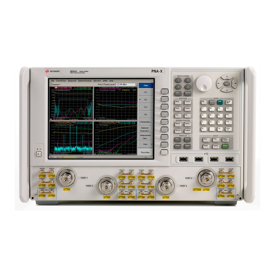
2-port and 4-port pna-x microwave network analyzers 10 mhz -13.5 ghz/10 mhz -26.5 ghz/10 mhz -8.5 ghz
Hide thumbs
Also See for N5241A:
- Installation note (50 pages) ,
- Configuration manual (37 pages) ,
- Security features and document of volatility (34 pages)
Table of Contents
Quick Links
See also:
Configuration Manual
Table of Contents
Troubleshooting

Related Manuals for Keysight N5241A


Summary of Contents for Keysight N5241A
- Page 1 Keysight 2-Port and 4-Port PNA-X Microwave Network Analyzers This manual provides documentation for the following models: N5241A (10 MHz -13.5 GHz) and N5242A (10 MHz-26.5 GHz) and N5249A (10 MHz-8.5 GHz) Service Guide...
-
Page 2: Safety Notices
DOCUMENT OR ANY INFORMATION reproduce, release, perform, CONTAINED HEREIN. SHOULD display, or disclose commercial KEYSIGHT AND THE USER HAVE A SEPARATE WRITTEN AGREEMENT computer software or WITH WARRANTY TERMS commercial computer software COVERING THE MATERIAL IN THIS... -
Page 3: Table Of Contents
Keysight Support, Services, and Assistance ........ - Page 4 IF Response Adjustment (Option 090, 093, or 094 Only) ......3-53 Noise Figure Adjustment (Available Only with Option 029 Installed) ....3-54 4. Troubleshooting Keysight N5241A/42A/49A Service Guide...
- Page 5 Instrument Block Diagrams Sheet 1 ......... . 4-49 Microwave PNA, N5241A/42A/49A 2-Port ........4-49 Instrument Block Diagrams Sheet 2 .
- Page 6 Front Panel Assembly, Front Side, All Options ....... . 6-11 Keysight N5241A/42A/49A Service Guide...
- Page 7 (For analyzers with serial numbers prefixed MY/SG/US5201 and above.) ... . . 7-17 Removing and Replacing the A14 System Motherboard ......7-20 Keysight N5241A/42A/49A Service Guide...
- Page 8 Option Entitlement Certificate ..........8-12 Keysight N5241A/42A/49A Service Guide...
- Page 9 Storing Correction Constants..........8-18 Keysight N5241A/42A/49A Service Guide...
- Page 10 Contents Keysight N5241A/42A/49A Service Guide...
-
Page 11: Safety And Regulatory Information
Keysight Microwave Network Analyzers 2-Port and 4-Port PNA-X Service Guide Safety and Regulatory Information Information in This Chapter This chapter provides safety information that will help protect you and your network analyzer. It also contains information that is required by various government regulatory agencies. -
Page 12: Safety Symbols
Warning denotes a hazard. It calls attention to a procedure which, if not correctly performed or adhered to, could result in injury or loss of life. Do not proceed beyond a warning note until the indicated conditions are fully understood and met. Keysight N5241A/42A/49A Service Guide... -
Page 13: General Safety Considerations
Degree 2 per IEC 61010-1:2001 and 664 respectively. Do not operate the analyzer with the outer cover removed for more than 30 minutes, as this could cause the analyzer to overheat which could result in costly damage. Keysight N5241A/42A/49A Service Guide... - Page 14 The measuring terminals on this instrument are designed to be used with external signals described in Measurement Category I, but NOT with external signals described in Categories II, III, and IV. The input of this instrument cannot be connected to the mains. Keysight N5241A/42A/49A Service Guide...
-
Page 15: Servicing
LINE switch (disconnecting device). There are no replaceable fuses in the mains input or within the power supply assembly. Keysight personnel: after calibration is completed, attach four “calibration void if seal broken” stickers to the PNA as shown in Figure 1-1. - Page 16 Safety and Regulatory Information General Safety Considerations Figure 1-1 Location of Calibration Stickers on PNA Keysight N5241A/42A/49A Service Guide...
-
Page 17: Electrostatic Discharge Protection
3. Connect the other end of the cable to the test port and remove the short from the cable. Figure 1-2 shows a typical ESD protection setup using a grounded mat and wrist strap. Refer to “ESD Supplies” on page 6-238 for part numbers. Keysight N5241A/42A/49A Service Guide... - Page 18 Safety and Regulatory Information Electrostatic Discharge Protection Figure 1-2 ESD Protection Setup Keysight N5241A/42A/49A Service Guide...
-
Page 19: Regulatory Information
Direct Current. IP 2 0 The instrument has been designed to meet the requirements of IP 2 0 for egress and operational environment. The RCM mark is a registered trademark of the Australian Communications and Media Authority. Keysight N5241A/42A/49A Service Guide... -
Page 20: Lithium Battery Disposal
If the battery on the A17 CPU board assembly needs to be disposed of, dispose of it in accordance with your country’s requirements. If required, you may return “Contacting the battery to Keysight Technologies for disposal. Refer to Keysight” on page 2-6 for assistance. -
Page 21: General Product Information
2-4 system verification, performance tests, adjustments, and troubleshooting. Keysight Support, Services, and The Internet address (URL) for on-line assistance. page 2-6 Assistance Service and support options available. Important information about shipping your analyzer to Keysight for service or repair. -
Page 22: Maintenance
Use a dry cloth or one slightly dampened with water to clean the external case parts. Do not attempt to clean internally. Electrical Maintenance “Review the Principles of Connector Care” on page 3-5. Refer to Keysight N5241A/42A/49A Service Guide... -
Page 23: Analyzer Options, Accessories, And Upgrades Available
Analyzer Options, Accessories, and Upgrades Available Analyzer Options, Accessories, and Upgrades Available To see a list of the options, accessories, and upgrades available for the network analyzers, including ordering information, refer to the Keysight PNA Family Microwave Network Analyzers Configuration Guide, available online at http://literature.cdn.keysight.com/litweb/pdf/5990-7745EN.pdf. -
Page 24: Required Service Test Equipment
The Z5623A has been discontinued, but it or the U3070A-K01 can be used. f. The recommended model or part number for all equipment listed with a “P” in the Use column is required for proper operation of the analyzer’s internal test software. Keysight N5241A/42A/49A Service Guide... - Page 25 Unless specified otherwise, equipment listed is required for all analyzer models. b. P = Performance tests, A = Adjustments, T = Troubleshooting, R = Repair, V = System verification c. Included in the 85052B/D calibration kits. Keysight N5241A/42A/49A Service Guide...
-
Page 26: Keysight Support, Services, And Assistance
Service and Support Options The analyzer’s standard warranty period is three-years from the time of initial delivery. All repairs require the analyzer to be shipped to the nearest Keysight Technologies service center. Extended warranty periods can be purchased with the initial product purchase. -
Page 27: Shipping Your Analyzer To Keysight For Service Or Repair
General Product Information Keysight Support, Services, and Assistance If you do not have access to the Internet, please contact your Keysight field engineer. In any correspondence or telephone conversation, refer to the Keysight product by its model number and full serial number. With this information, the Keysight representative can determine whether your product is still within its warranty period. - Page 28 General Product Information Keysight Support, Services, and Assistance Keysight N5241A/42A/49A Service Guide...
-
Page 29: Tests And Adjustments
Keysight Microwave Network Analyzers 2-Port and 4-Port PNA-X Service Guide Tests and Adjustments Information in This Chapter This chapter contains procedures to help you check, verify, and adjust your PNA. — The checks verify the operation of the assemblies in your analyzer. - Page 30 Receiver Compression Test Noise Floor Test — Calibration Coefficients Test — — Dynamic Accuracy Test – Version 1 System Noise Figure Test — Noise Jitter Test — — Noise Receiver Linearity Test Noise Receiver Compression Test — Keysight N5241A/42A/49A Service Guide...
- Page 31 IF Response Adjustment (Option 090, 093, or 094 Only) — — Example a. These performance tests are included in the analyzer’s firmware for Options 897 and 898. b. These adjustments are included in the analyzer’s firmware on all models and options. Keysight N5241A/42A/49A Service Guide...
-
Page 32: Before You Begin
To reduce the chance of electrostatic discharge, follow all of the recommendations outlined in “Electrostatic Discharge Protection” on page 1-7, for all of the procedures in this chapter. Keysight N5241A/42A/49A Service Guide... -
Page 33: Allow The Analyzer To Warm Up
— Use an out-of-specification connector — Use the correct gage type — Use correct end of calibration block — Gage all connectors before first use Making Connections — Align connectors carefully Do Not — Apply bending force to connection Keysight N5241A/42A/49A Service Guide... - Page 34 Cleaning connectors with alcohol shall only be done with the instrument’s power cord removed, and in a well-ventilated area. Allow all residual alcohol moisture to evaporate, and the fumes to dissipate prior to ener- gizing the instrument. Keysight N5241A/42A/49A Service Guide...
-
Page 35: About System Verification And Performance Tests
— Complete all of the performance tests using a certified calibration kit that will be used for future measurements. This alternative verifies both the system specifications and the instrument specifications for the analyzer. Keysight N5241A/42A/49A Service Guide... -
Page 36: Instrument Specifications
An illustrated outline of the performance verification procedure: — for ANSI/NCSL Z540.3-2006 and ISO/IEC 17025 verification, is shown in Figure 3-1 on page 3-10. Figure 3-2 on page 3-11. — for non-standards verification, is shown in Keysight N5241A/42A/49A Service Guide... -
Page 37: Certificate Of Calibration
If you have a measurement application that does not use all of the measurement capabilities of the analyzer, you may ask your local Keysight Technologies service office to verify only a subset of the specifications. However, this “limited calibration” creates the possibility of making inaccurate measurements if you then use the analyzer in an application requiring additional capabilities. -
Page 38: Ansi/Ncsl Z540.3-2006 And Iso/Iec Verification
Figure 3-1 ANSI/NCSL Z540.3–2006 and ISO/IEC 17025 Verification Flowchart 1. Stop only in case of a catastrophic failure or cable connector damage 3-10 Keysight N5241A/42A/49A Service Guide... -
Page 39: Non-Standards Compliant Verification
Troubleshoot and repair the first problem encountered without continuing to other tests. After you troubleshoot, repair, and adjust, repeat the last failed portion and generate a new set of data. Figure 3-2 Non–Standards Compliant Verification Flowchart Keysight N5241A/42A/49A Service Guide 3-11... -
Page 40: Preliminary Checks
Shorts/Opens are attached to ALL ports, to run through the test without stopping. Shorts and opens can be mixed on the test ports. 3-12 Keysight N5241A/42A/49A Service Guide... - Page 41 Figure 3-3). The PNA Operator’s Check dialog box will look different for different PNA model numbers and installed options. Some of the tests are performed only if the appropriate options are installed in the PNA. Keysight N5241A/42A/49A Service Guide 3-13...
- Page 42 Tests and Adjustments Preliminary Checks Figure 3-3 Operator’s Check Dialog Boxes 3-14 Keysight N5241A/42A/49A Service Guide...
-
Page 43: The Test Port Cable Checks
7. The marker annotation on the screen indicates the worst case return loss. Refer to the cable manual to see if it meets the return loss specification. For an example of a typical return loss measurement, see Figure 3-4. Keysight N5241A/42A/49A Service Guide 3-15... - Page 44 CalSet_1.cst. 6. Connect the test port cable to the PNA Port 1 and perform a 1-port calibration again at the end of the cable. After calibration, save the cal set data as CalSet_2.cst. 3-16 Keysight N5241A/42A/49A Service Guide...
- Page 45 Help section “Save and Recall a File” if necessary. 10.Refer to the cable manual to see if it meets the insertion loss specification. For an example of a typical insertion loss measurement, see Figure 3-6. Keysight N5241A/42A/49A Service Guide 3-17...
- Page 46 ON. Average on/OFF The Averaging Factor box will appear directly above the display. In the Averaging Factor box, type 50 or click the arrows to select 50, and then press ENTRY Enter 3-18 Keysight N5241A/42A/49A Service Guide...
- Page 47 Therefore, the measured deflection value must be divided in half to reach the correct value. Figure 3-7 Typical Cable Magnitude and Phase Stability Response Keysight N5241A/42A/49A Service Guide 3-19...
- Page 48 7. Disconnect and then reconnect the cable to the test port. Tighten the connection to the specified torque for the connector type. 8. Press RESPONSE , then Averaging Restart 9. Look at the trace for spikes or modes. 3-20 Keysight N5241A/42A/49A Service Guide...
- Page 49 Typical Cable Connector Repeatability Response If the Cable Connector Repeatability Check Fails 1. Clean the cable and devices, and torque to specification. Repeat the check. 2. If the check still fails, the cable should be repaired or replaced. Keysight N5241A/42A/49A Service Guide 3-21...
-
Page 50: System Verification
Measurement Uncertainty Measurement uncertainty is defined as the sum of: — the residual systematic (repeatable) errors, and — the random (non-repeatable) errors in the measurement system after calibration. The systematic errors are: 3-22 Keysight N5241A/42A/49A Service Guide... -
Page 51: Measurement Traceability
This is accomplished by measuring the devices in a Keysight verification kit. The measurement of the devices in the verification kit has a traceable path... -
Page 52: Performing System Verification
If you select to perform a calibration, you are guided through the calibration procedure. This part of the process can be eliminated if you 3-24 Keysight N5241A/42A/49A Service Guide... - Page 53 It is highly recommended that the test port cables be regularly tested. If the system verification is performed with a non-Keysight cable, ensure that the cable meets or exceeds the specifications for the test cable specified in the “Equipment Used in the System Verification Procedure.”...
- Page 54 Tests and Adjustments System Verification Kit Substitution Non-Keysight calibration kits and verification kits are not recommended nor supported. System Verification Procedure 1. If you desire printed test outputs, connect a printer to the analyzer. For the printer, ensure that the correct driver is loaded and the printer is defined as the default printer.
- Page 55 3-13 on page 3-31. — File Tabular Data: Writes the tabular data to a text file in the Windows XP directory C:\Program Files\Keysight\Network Analyzer\Documents\ or the Windows 7 directory C:\Users\Public\Public Documents\Network Analyzer\Documents\SysVer. — File Graphs: Saves a screen image in PNG format in the Windows XP...
- Page 56 At the top of the printed output is the name of the device, the serial number of the device, and the date tested. Each S-parameter measurement result is printed with frequency tested, lower and upper limit lines, the measured data, and the result of the test. 3-28 Keysight N5241A/42A/49A Service Guide...
- Page 57 Tests and Adjustments System Verification Figure 3-12 Example of Printed Tabular Verification Results Keysight N5241A/42A/49A Service Guide 3-29...
- Page 58 — Data measured at the factory from the verification kit. Labeled as B in Figure 3-13. — Upper and lower limit points as defined by the total system uncertainty Figure 3-13. system. Labeled as C in 3-30 Keysight N5241A/42A/49A Service Guide...
- Page 59 Tests and Adjustments System Verification Figure 3-13 Example of Printed Graphical Verification Results Keysight N5241A/42A/49A Service Guide 3-31...
-
Page 60: Performance Tests
— Power meter — Power sensors — Any necessary adapters Description of the Test: 1. The analyzer is Preset. 2. The analyzer is set up for a CW reflection measurement on the test port to be measured. 3-32 Keysight N5241A/42A/49A Service Guide... -
Page 61: Source Maximum Power Output Test
The output power is then decreased in increments of 0.01 dB until the error goes away. if the output power reaches +18 dBm without any error, the power is left at this level. Keysight N5241A/42A/49A Service Guide 3-33... -
Page 62: Source Power Linearity Test
Preset and the change in the receiver power reading. 7. This power linearity measurement is repeated at several CW frequencies across the full frequency range of the analyzer. If the Analyzer Fails this Test: 3-34 Keysight N5241A/42A/49A Service Guide... -
Page 63: Frequency Accuracy Test
— Verify the accuracy of the 10 MHz OCXO by using a frequency counter to measure the rear-panel 10 MHz REF OUT. If the 10 MHz reference is off by “10 MHz Frequency Reference Adjustment” more than 10 Hz, perform the on page 3-48 and then repeat this test. Keysight N5241A/42A/49A Service Guide 3-35... -
Page 64: Trace Noise Test
A4–A13 Boards (For analyzers with serial numbers prefixed MY/SG/US5201 and above.)” on page 7-17. — If the analyzer still fails this test, replace the mixer module for the failing receiver, and then repeat this test. 3-36 Keysight N5241A/42A/49A Service Guide... -
Page 65: Receiver Compression Test
8. The first test set output attenuator is set to 20 dB. 9. The magnitude and phase measurements using the receiver under test are read: (Pb). 10.The second test set output attenuator is set to 20 dB. Keysight N5241A/42A/49A Service Guide 3-37... -
Page 66: Noise Floor Test
5. For hundreds of frequencies across the analyzer’s full range, a source power calibration is performed to ensure a flat power response at the end of the cable at the Preset power level. 3-38 Keysight N5241A/42A/49A Service Guide... -
Page 67: Calibration Coefficients Test
2. A calibration is performed between the end of the test cable and Port 2. The Port 2 directivity and source match and the S21 load match are retrieved from the analyzer. 3. The test cable is moved to Port 2. Keysight N5241A/42A/49A Service Guide 3-39... -
Page 68: Dynamic Accuracy Test - Version 1
Dynamic Accuracy Test – Version 1 This description applies to all E836xA/B/C and N5230A/C instruments. It also applies to N5241A/42A/44A/45A instruments with serial numbers less than xx5240xxxx. For all other instruments, see test version 2. Function of the Test: To measure the relative power linearity of the analyzer’s receivers. -
Page 69: Dynamic Accuracy Test - Version 2
Dynamic Accuracy Test – Version 2 This description applies to all N522xA, N5231A/32A/34A/35A/39A, and N5247/49A instruments. It also applies to N5241A/42A/44A/45A instruments with serial numbers greater than xx5240xxxx. It also applies to N5241A/42A/44A/45A instruments with serial numbers less than xx5240xxxx. - Page 70 — If the analyzer still fails this test, replace the A12 SPAM board and repeat “Removing and Replacing the A4–A13 Boards (For this test. Refer to analyzers with serial numbers prefixed MY/SG/US5201 and above.)” on page 7-17. 3-42 Keysight N5241A/42A/49A Service Guide...
-
Page 71: System Noise Figure Test
“Removing and Replacing the A4–A13 Boards (For analyzers with serial numbers prefixed MY/SG/US5150 and below.)” on page 7-14 “Removing and Replacing the A4–A13 Boards (For analyzers with serial numbers prefixed MY/SG/US5201 and above.)” on page 7-17. Keysight N5241A/42A/49A Service Guide 3-43... -
Page 72: Noise Jitter Test
MY/SG/US5201 and above.)” on page 7-17. Noise Receiver Linearity Test Function of the Test: To measure the relative power linearity of the analyzer’s noise receiver. Specification Tested: Test Port Input: Option 029 – Noise Receiver Linearity Equipment Used: 3-44 Keysight N5241A/42A/49A Service Guide... - Page 73 The process is repeated until the total attenuation reaches the minimum test level. 10.The process is reset to the reference levels from step 4, and it is run in reverse until the total attenuation reaches the maximum test level. Keysight N5241A/42A/49A Service Guide 3-45...
-
Page 74: Noise Receiver Compression Test
3. Using the low frequency power sensor, a source power calibration is performed at the end of the cable for dozens of frequency points. The power level is set between -9 and -18 dBm, at a multiple of 10 dB above the specified compression level. 3-46 Keysight N5241A/42A/49A Service Guide... - Page 75 “Removing and Replacing the A4–A13 Boards (For analyzers with serial numbers prefixed MY/SG/US5150 and below.)” on page 7-14 “Removing and Replacing the A4–A13 Boards (For analyzers with serial numbers prefixed MY/SG/US5201 and above.)” on page 7-17. Keysight N5241A/42A/49A Service Guide 3-47...
-
Page 76: Adjustments
Any that will measure a signal at 10 MHz. Procedure This adjustment typically adjusts to within ±0.01 ppm. 1. Connect the equipment as shown in Figure 3-14. Connect a GPIB cable between the network analyzer and the frequency counter. 3-48 Keysight N5241A/42A/49A Service Guide... -
Page 77: Synthesizer Bandwidth Adjustment
Equipment Used for the Source Adjustment Equipment Type Model or Al ternate Model or Part Number Part Number Power meter E4418B/E4419B E4418A/E4419A Power sensor, 3.5 mm E4413A 8485A Adapter, 3.5 mm (f) to 3.5 mm (f) 83059B 85052-60012 Keysight N5241A/42A/49A Service Guide 3-49... -
Page 78: If Gain Adjustment
2. Follow the instructions and prompts as they are displayed. Receiver Characterization This characterizes the receivers in your analyzer. Procedure Service Adjustments 1. Press UTILITY System , then , then , then click Receiver Characterization. 3-50 Keysight N5241A/42A/49A Service Guide... -
Page 79: Receiver Adjustment
83059B 85052-60012 RF Cable, 3.5 mm (f) to 3.5 mm (f) 85131C 85131E Procedure 1. Connect the equipment as shown in Figure 3-16. Connect a GPIB cable between the network analyzer and the power meter. Keysight N5241A/42A/49A Service Guide 3-51... - Page 80 , then , then , then click Receiver Adjustment. 3. Ensure the GPIB settings are correct. 4. Follow the instructions and prompts as they are displayed. Figure 3-17 Equipment Setup 2 for the Receiver Adjustment 3-52 Keysight N5241A/42A/49A Service Guide...
-
Page 81: Ee Default Adjustment
Procedure Service Adjustments 1. Press UTILITY , then , then , then click IF System Response Adjustment. 2. Follow the instructions and prompts as they are displayed. Keysight N5241A/42A/49A Service Guide 3-53... -
Page 82: Noise Figure Adjustment (Available Only With Option 029 Installed)
Create New to enter data for the noise source you are using. The PNA will automatically remember and use the last file selected. These files should normally reside in the C:\Program Files\Keysight\Network Analyzer\Noise directory, but can also exist elsewhere. 3-54... - Page 83 1 and 2. Figure 3-20 Equipment Setup 1 for the Receiver Adjustment 5. When prompted, connect the noise source to port 2, either directly or with a short, low-loss adapter. See Figure 3-21. Keysight N5241A/42A/49A Service Guide 3-55...
- Page 84 2 and the free end of the cable. Connect the ECal module directly to port 2 without using any adapters if possible. See Figure 3-22 Figure 3-22 Equipment Setup 3 for the Receiver Adjustment The entire procedure takes about 15 to 30 minutes. 3-56 Keysight N5241A/42A/49A Service Guide...
-
Page 85: Troubleshooting
Keysight Microwave Network Analyzers 2-Port and 4-Port PNA-X Service Guide Troubleshooting Information in This Chapter The information in this chapter helps you: — Identify the portion of the analyzer at fault. — Locate the specific troubleshooting procedure to identify the assembly or peripheral at fault. -
Page 86: Chapter Four At-A-Glance
This represents a “hardkey”, a key that is physically located on the instrument. Hardkey This represents a “softkey”, a key whose label is determined by the instrument Softkey firmware. Menu Item This represents an item in a drop-down or pop-up menu. Keysight N5241A/42A/49A Service Guide... -
Page 87: Operating The Analyzer With Covers Removed
Operating the Analyzer With Covers Removed Operating the Analyzer With Covers Removed Do not operate the analyzer with the outer cover removed for more than 30 minutes, as this could cause the analyzer to overheat which could result in costly damage. Keysight N5241A/42A/49A Service Guide... -
Page 88: Protect Against Electrostatic Discharge (Esd)
To reduce the chance of electrostatic discharge, follow all of the recommendations outlined in “Electrostatic Discharge Protection” on page 1-7, for all of the procedures in this chapter. Keysight N5241A/42A/49A Service Guide... -
Page 89: Assembly Replacement Sequence
Step 2. Replace the faulty assembly and determine what adjustments are necessary. Refer to Chapter 7, “Repair and Replacement Procedures.” Step 3. Perform the necessary adjustments. Refer to Chapter 3, “Tests and Adjustments.” Step 4. Perform the necessary performance tests. Refer to Chapter 3, “Tests and Adjustments.” Keysight N5241A/42A/49A Service Guide... -
Page 90: Getting Started With Troubleshooting
Check the Basics A problem can often be solved by repeating the procedure you were following when the problem occurred. Before calling Keysight Technologies or returning the instrument for service, please perform the following checks: 1. Is there power at the mains receptacle? If not, correct this situation and proceed. - Page 91 Troubleshooting Getting Started with Troubleshooting Figure 4-1 Troubleshooting Organization Flowchart “Power Up Go to Troubleshooting” “Front Panel Go to Troubleshooting” “Rear Panel Go to Troubleshooting” “Measurement Go to System Troubleshooting” Keysight N5241A/42A/49A Service Guide...
-
Page 92: Power Up Troubleshooting
— If the line switch glows green and the fans are operating (audible), but the “Troubleshooting LCD Display Problems” on display remains dark, go to page 4-15. — If the instrument appears to abort the network analyzer measurement “Contacting Keysight” on interface process, contact Keysight. Refer to page 2-6. Keysight N5241A/42A/49A Service Guide... -
Page 93: Power Supply Check
ACOM as ground reference for analog supplies and the point marked DCOM as ground reference for digital supplies. Figure 4-2 Refer to for the power supply measurement points on the A15 Table 4-1 on page 4-12 midplane board. Refer to for the correct voltages. Keysight N5241A/42A/49A Service Guide... - Page 94 Failure to do so can result in personal injury or loss of life. Do not operate the analyzer with the outer cover removed for more than 30 minutes, as this could cause the analyzer to overheat which could result in costly damage. 4-10 Keysight N5241A/42A/49A Service Guide...
- Page 95 A16 power supply provides voltage. To isolate the cause, continue to the assembly removal process as described in the section titled “If Any Supply Voltage Is Missing” on page 4-12. Keysight N5241A/42A/49A Service Guide 4-11...
- Page 96 A20 IF Multiplexer Board” on page 7-34). 3. Unplug the front panel interface cable from the A1 front panel interface board (refer to “Removing the A1 Front Panel Interface Board and Keypad Assembly” on page 7-10). 4-12 Keysight N5241A/42A/49A Service Guide...
- Page 97 ACOM or DCOM. If the Fans Are Not Operating The power supply may be in thermal shutdown if the instrument has been operating without the fans running. Allow the instrument to cool down before troubleshooting. Keysight N5241A/42A/49A Service Guide 4-13...
- Page 98 A14 system motherboard. THIS MUST BE DONE QUICKLY AS THE ANALYZER WILL RAPIDLY OVERHEAT WITHOUT THE COOLING EFFECT OF THE FANS. DO NOT PLUG IN THE POWER CORD UNTIL READY TO PERFORM MEASUREMENTS. Figure 4-3 Fan Power Cable Connections 4-14 Keysight N5241A/42A/49A Service Guide...
-
Page 99: Troubleshooting Lcd Display Problems
4. If the front panel interface ribbon cable is properly connected, suspect that one or more of the following is defective: — inverter board (mounted on the display assembly) — A1 front panel interface board — A3 display assembly Keysight N5241A/42A/49A Service Guide 4-15... -
Page 100: Front Panel Troubleshooting
Service More Front Panel Test System Press UTILITY , then , then , then A Front Panel Key Test Utility dialog box will be displayed, as shown in Figure 4-4. 4-16 Keysight N5241A/42A/49A Service Guide... - Page 101 “Removing the A1 Front Panel Interface Board and Keypad Assembly” on page 7-10. Table 4-2 Front Panel Keyboard Key Names TRACE/CHAN RESPONSE ENTRY ENTRY Keys Keys Keys Keys (Cont’d) Trace 1 Meas Trace 2 Format Cancel Enter Trace 3 Scale Help . (decimal point) Keysight N5241A/42A/49A Service Guide 4-17...
- Page 102 3. If the movement of numbers is not smooth or no numbers appear at all, suspect a faulty A1 front panel interface board. To replace the A1 front panel interface board, refer to “Removing the A1 Front Panel Interface Board and Keypad Assembly” on page 7-10. 4-18 Keysight N5241A/42A/49A Service Guide...
-
Page 103: A3 Display Test
— If the device performs correctly, the USB board is functioning properly. — If the device does not perform correctly, the USB board is faulty. Refer to “Removing the A2 USB Board” on page 7-10. Keysight N5241A/42A/49A Service Guide 4-19... -
Page 104: A1 Front Panel Interface Board
Checking the Operation of the Key Pad Commands “Front Panel Keypad and RPG Test” To verify the key pad functionality, refer to on page 4-16. Checking the Display “A3 Display Test” on page 4-19. To verify the display functionality, refer to 4-20 Keysight N5241A/42A/49A Service Guide... -
Page 105: Rear Panel Troubleshooting
, then Configure , then SICL/GPIB... SICL/GPIB/SCPI dialog box is displayed. 3. In the GPIB block, click System Controller to establish the analyzer as a controller. Wait for the analyzer to configure, and then click OK. Keysight N5241A/42A/49A Service Guide 4-21... -
Page 106: Lan Troubleshooting
Problems with the Local Area Network (LAN) can be difficult to solve. Software and protocol problems can make it difficult to determine whether the analyzer's hardware is working properly, or if there is a problem with the LAN or cabling. 4-22 Keysight N5241A/42A/49A Service Guide... - Page 107 Windows Taskbar menu at the bottom of the display. b. On the Windows Taskbar menu, click Start, point to Programs, Accessories, and then click Command Prompt. c. The command prompt window is displayed. Keysight N5241A/42A/49A Service Guide 4-23...
- Page 108 Other software may behave somewhat differently, but basically the same. 1. The letters x represent the IP address of the other device on the network. 2. The letters x represent the IP address of the analyzer. 4-24 Keysight N5241A/42A/49A Service Guide...
- Page 109 A crossover cable can be made from a standard LAN cable by connecting pin 1 from each connector to pin 3 of the other connector, and pin 2 from each connector to pin 6 of the other connector. Keysight N5241A/42A/49A Service Guide 4-25...
- Page 110 Most, but not all, LAN cables use the color coding listed in Table 4-3. If your cable does not use this color scheme, you will have to determine the locations of the appropriate wires before proceeding with this procedure. 4-26 Keysight N5241A/42A/49A Service Guide...
- Page 111 2 on the other end of the cable. 3. Insulate all exposed wires so that they cannot short together. 4. Label this as a crossover cable so that it cannot be confused with a standard cable. Keysight N5241A/42A/49A Service Guide 4-27...
- Page 112 Troubleshooting Rear Panel Troubleshooting Figure 4-5 Construction of a Crossover Cable 4-28 Keysight N5241A/42A/49A Service Guide...
-
Page 113: Measurement System Troubleshooting
Help , then About NA..Verify that the information displayed in this screen is correct for your analyzer. If any of the information is incorrect, contact Keysight “Contacting Keysight” on page 2-6. Technologies. Refer to Keysight N5241A/42A/49A Service Guide... -
Page 114: Verifying The A, B, C, D, And R Traces (Standard S-Parameter Mode)
, then , then View EEPROM Headers Figure 4-6. . Refer to If the information is incorrect for any of the PC boards, contact Keysight Technologies. Refer to “Contacting Keysight” on page 2-6. Figure 4-6 EEPROM Header Info Dialog Window... - Page 115 — For 4-port analyzer models, traces A, B, C, D, R1, R2, R3, and R4 are Figure 4-8. displayed in eight separate data windows as shown in Identifying discrepancies of the traces in these windows can help you to isolate the faulty assembly. Keysight N5241A/42A/49A Service Guide 4-31...
-
Page 116: Where To Begin Troubleshooting
“Contacting — If a problem still exists, contact Keysight. Refer to Keysight” on page 2-6. — If any of the traces are not present, are noisy or distorted, or are at an incorrect level, then there is a problem with the analyzer’s measurement... - Page 117 Good judgement and established logical troubleshooting techniques must be used to complement the procedures contained in this section. All Traces Keysight N5241A/42A/49A Service Guide 4-33...
- Page 118 Properties in the resulting pop-up menu. Click the Hard ware tab, click Device Manager, and then expand Keysight PNA DSP Device in the resulting list. The following entry should be listed: Keysight Technologies DSP Driver #2 and should be enabled.
-
Page 119: Checking The Source Group
Equipment Used for This Check Equipment Type Model or Al ternate Model or Part Number Part Number Power meter E4418B/E4419B E4418A/E4419A Power sensor, 2.4 mm E8487A None Adapter, 2.4 mm (f) to 2.4 mm (f) 11900B 85056-60007 Keysight N5241A/42A/49A Service Guide 4-35... - Page 120 Refer to “Removing and Replacing the A4–A13 Boards (For analyzers with serial numbers prefixed MY/SG/US5150 and below.)” on page 7-14. 6. If the 50 MHz signals are present, reconnect the cables, and then: 4-36 Keysight N5241A/42A/49A Service Guide...
- Page 121 4-29 CW frequency and observe the spectrum analyzer measurement. For analyzers with DSP version 4.0, an 807.61 MHz signal should be present. For analyzers with DSP version 5.0, an 807.44 MHz signal should be present. Keysight N5241A/42A/49A Service Guide 4-37...
- Page 122 A22 splitter. Refer to “Removing and Replacing the A22 Splitter” on page 7-38. 7. If the signal is present, reconnect cables W43 and W44, and then continue with “Checking the Receiver Group” on page 4-44. 4-38 Keysight N5241A/42A/49A Service Guide...
- Page 123 4-29. If the observed problem was frequency banded rather than broadband related, set the analyzer frequency to the center of the problem band. The spectrum analyzer should measure a signal above the network analyzer setting. For analyzers with DSP version Keysight N5241A/42A/49A Service Guide 4-39...
-
Page 124: Checking The Signal Separation Group
The measurement results will help you isolate a faulty assembly. The output of the R receiver cannot be measured because it would necessitate breaking the phase lock loop, causing all of the signals to be lost. 4-40 Keysight N5241A/42A/49A Service Guide... - Page 125 For all of the following checks, refer to the block diagrams at the end of this chapter and to any of the following that are appropriate: “2-Port Configuration, Option 200” on page 6-25 — “Bottom RF Cables, Standard 2-Port Configuration, Option 200” on — page 6-28 Keysight N5241A/42A/49A Service Guide 4-41...
- Page 126 Perform the following checks in the order presented. Checking the A25, A26, A27, and A28 Bridges 1. Locate the appropriate semirigid cable at the output of the bridge to be checked: — Options 200 and 400 4-42 Keysight N5241A/42A/49A Service Guide...
- Page 127 — Port 1; W72 of A34 — Port 2; W84 of A37 — Port 3; W76 of A35 — Port 4; W80 of A36 2. Using a 5/16-inch torque wrench, disconnect the semirigid cable at the step attenuator. Keysight N5241A/42A/49A Service Guide 4-43...
-
Page 128: Checking The Receiver Group
DSP version 4.0), or 7.44 MHz (analyzers with DSP version 5.0), and 1 GHz. For all of the following checks, refer to the block diagrams at the end of this chapter and to any of the following that are appropriate: 4-44 Keysight N5241A/42A/49A Service Guide... - Page 129 4. With the covers off, plug in the analyzer and turn on the power. Do not operate the analyzer with the outer cover removed for more than 30 minutes, as this could cause the analyzer to overheat which could result in costly damage. Keysight N5241A/42A/49A Service Guide 4-45...
- Page 130 If the measured signal is missing on the A, B, C, or D receivers and the analyzer has receiver attenuators, continue testing at “Checking the A42, A43, A44, and A45 35-dB Receiver Step Attenuators” on page 4-47. 4-46 Keysight N5241A/42A/49A Service Guide...
- Page 131 1. Locate each of the flexible RF cables at the output receivers of the IF multiplexer board: — 2-port models — Receiver A; W59 — Receiver R1; W60 — Receiver R2; W61 — Receiver B; W62 — 4-port models Keysight N5241A/42A/49A Service Guide 4-47...
- Page 132 MY/SG/US5150 and below.)” on page 7-14. 6. If the measured signal is not present replace the A20 IF multiplexer board. Refer to “Removing and Replacing the A20 IF Multiplexer Board” on page 7-34. 4-48 Keysight N5241A/42A/49A Service Guide...
-
Page 133: Instrument Block Diagrams Sheet 1
Troubleshooting Instrument Block Diagrams Sheet 1 Instrument Block Diagrams Sheet 1 Microwave PNA, N5241A/42A/49A 2-Port Keysight N5241A/42A/49A Service Guide 4-49... - Page 134 N5241A , N5242A and N5249A 2-Port Overall Block Diagram (Includes Options 200-Standard; 219-Attenuators and Bias Tees; 224-Source Bypass Switches; and Port 1 OPTION 200 USB BD 029-Noise Figure) DISPLAY A20 IF MULTIPLEXER RCVR A IN A12 SIGNAL PROCESSING SPAM 4: IF = 2.535 MHz for CW Freq < 53 MHz...
-
Page 135: Instrument Block Diagrams Sheet 2
Troubleshooting Instrument Block Diagrams Sheet 2 Instrument Block Diagrams Sheet 2 Microwave PNA, N5241A/42A/49A 2-Port with Option H85 Keysight N5241A/42A/49A Service Guide 4-51... - Page 136 N5241A , N5242A and N5249A 2-Port Overall Block Diagram (Includes Options 200-Standard; H85-High Power Configuration; 224-Source Bypass Switches; and A42 STEP Port 1 ATTEN W88 - (219, 224) W87 - (219, 224) 029-Noise Figure) DISPLAY USB BD A20 IF MULTIPLEXER...
-
Page 137: Instrument Block Diagrams Sheet 3
Troubleshooting Instrument Block Diagrams Sheet 3 Instrument Block Diagrams Sheet 3 Microwave PNA, N5241A/42A/49A 4-Port Keysight N5241A/42A/49A Service Guide 4-53... - Page 138 N5241A, N5242A and N5249A 4-Port Overall Block Diagram (Includes Options 400-Standard; 419-Attenuators and Bias Tees; 423-Source Bypass Switches; and Port 1 OPTION 400 029-Noise Figure) DISPLAY USB BD A20 IF MULTIPLEXER RCVR A IN A12 SIGNAL PROCESSING SPAM 4: IF = 2.535 MHz for CW Freq < 53 MHz...
-
Page 139: Instrument Block Diagrams Sheet 4
Troubleshooting Instrument Block Diagrams Sheet 4 Instrument Block Diagrams Sheet 4 Microwave PNA, N5241A/42A/49A 4-Port with Option H85 Keysight N5241A/42A/49A Service Guide 4-55... - Page 140 N5241A , N5242A and N5249A 4-Port Overall Block Diagram (Includes Options 400-Standard; H85-High Power Configuration; 423-Source Bypass Switches; and A42 STEP Port 1 ATTEN W88 - (419, 423) W87 - (419, 423) 029-Noise Figure) DISPLAY USB BD A20 IF MULTIPLEXER...
-
Page 141: Theory Of Operation
Information in This Chapter This chapter provides a general description of the operating theory of the N5241A/42A 2-port and 4-port PNA microwave network analyzers. — Theory of operation is explained to the assembly level only. — Component-level circuit theory is not provided. - Page 142 Operation (Option 029) measurement group. Digital Processing and Digital Operation of the assemblies associated with digital page 5-31 Control Group Operation processing and digital control. Power Supply Group Operation Operation of the power supply assembly group. page 5-36 Keysight N5241A/42A/49A Service Guide...
-
Page 143: Network Analyzer System Operation
SRC 2 OUT 1 and SRC 2 OUT 2. Figure 5-1 is a simplified block diagram of the 4-port network analyzer system Figure 5-2 is a simplified block diagram of the 2-port network analyzer system. Figure 5-1 4-Port System Simplified Block Diagram Keysight N5241A/42A/49A Service Guide... -
Page 144: Functional Groups Of The Network Analyzer
The major functional groups are: Synthesized Source Group — Signal Separation Group — Receiver Group — Noise Measurement Group (Option 029) — Digital Processor and Digital Control Group — Power Supply Group — Keysight N5241A/42A/49A Service Guide... - Page 145 Instrument Ports Preset 16 GHz 24 GHz 26.5 10 GHz 20 GHz 0 dBm 0 dBm -5 dBm -5 dBm -5 dBm -5 dBm +5 dBm SRC 2 OUT 1 +5 dBm SRC 2 OUT 2 Keysight N5241A/42A/49A Service Guide...
- Page 146 26.5 GHz. It converts the noise signals to intermediate frequency (IF) signals. The IF signals are then processed, sampled, and converted into digital information. The noise measurement group also enables fully-corrected noise figure measurements using a Keysight Electronic Calibration (ECal) Module (ordered separately), configured as an impedance tuner.
- Page 147 “Digital Processing and Digital Control Group Operation” on Refer to page 5-31. Power Supply Group The power supply functional group provides power for the other assemblies in the instrument. “Power Supply Group Operation” on page 5-36. Refer to Keysight N5241A/42A/49A Service Guide...
-
Page 148: Synthesized Source Group Operation
The A4, A13, and A11 13.5 GHz synthesizer boards each contain their own phase lock circuitry. The A11 board is used to phase lock the LO signal while the A4 and A13 boards are used to phase lock the test signal. This makes it Keysight N5241A/42A/49A Service Guide... - Page 149 7.606 MHz. For analyzers with DSP version 5.0, the frequency value is 7.438 MHz. Since the A4, A13, and A11 13.5 GHz synthesizer boards each receive their 50 MHz input reference signal from the exact same source, frequency drift error is eliminated. Keysight N5241A/42A/49A Service Guide...
- Page 150 Theory of Operation Synthesized Source Group Operation Figure 5-3 Source Group 5-10 Keysight N5241A/42A/49A Service Guide...
- Page 151 8.00761 to 8.50761 8.00761 to 8.50761 8.000 to 8.500 8.000 to 8.500 8.50761 to 10.67161 8.50761 to 10.67161 8.500 to 10.664 8.500 to 10.664 10.67161 to 12.00761 10.67161 to 12.00761 10.664 to 12.000 10.664 to 12.000 Keysight N5241A/42A/49A Service Guide 5-11...
-
Page 152: A4, A13, And A11 13.5 Ghz Synthesizer Boards
21–23 and 29–30 are sent directly to the output of the synthesizer board while bands 26–28 and 34–36 are passed through another doubler circuit then to the output of the synthesizer board to produce the Table 5-3. output frequencies listed in 5-12 Keysight N5241A/42A/49A Service Guide... -
Page 153: A5 And A8 26.5 Ghz Source Boards
Together, these signal paths create the full output frequency range of 12.5 MHz to 26.508 GHz that is sent to the A22 splitter (4-port only) where the signal is divided and sent to the A23 and A24 (4-port only) mixer bricks as the LO signal. Keysight N5241A/42A/49A Service Guide 5-13... -
Page 154: A10 Frequency Reference Board
Pin assignments are listed in Table 5-3 on page 5-15. Up to 16 test sets may be “daisy-chained” on the bus at one time. The Test Set I/O is not compatible with 8753 network analyzer test sets. 5-14 Keysight N5241A/42A/49A Service Guide... - Page 155 TTL out, test set select bit 3, tied to 0 V 19–21 AD7–5 TTL I/O, address and latched data 22–23 AD0–1 TTL I/O, address and latched data TTL out, active low data strobe (1 μs min) TTL out, high = read, low = write Keysight N5241A/42A/49A Service Guide 5-15...
- Page 156 TTL out, active low pass/fail write strobe (1 μs min) Strobe Table 5-5 PWR I/O Connector Pin Assignments DB-9 Female Connector Name Description +15V +15 V @ 400 mA -15V −15 V @ 400 mA 5-16 Keysight N5241A/42A/49A Service Guide...
- Page 157 Analog input: ±10 V @ 1.22 mV typical resolution Rin > 1 M-ohm BW ≈ 1 MHz ADC conversion time < 1 us typical Power Button Open collector input Active low replicates power button key press. Keysight N5241A/42A/49A Service Guide 5-17...
-
Page 158: Signal Separation Group Operation
— the A26 port 3 bridge and the A30 test port 3 coupler — the A27 port 4 bridge and the A31 test port 4 coupler — the A28 port 2 bridge and the A32 test port 2 coupler 5-18 Keysight N5241A/42A/49A Service Guide... -
Page 159: A25-A28 Bridges
A, B, C, and D for 4-port models or inputs A and B for 2-port models. The coupling coefficient of the directional couplers is nominally 15 dB over the full frequency range. Keysight N5241A/42A/49A Service Guide 5-19... - Page 160 Theory of Operation Signal Separation Group Operation Figure 5-4 4-Port Signal Separation Group 5-20 Keysight N5241A/42A/49A Service Guide...
- Page 161 Theory of Operation Signal Separation Group Operation Figure 5-5 2-Port Signal Separation Group Keysight N5241A/42A/49A Service Guide 5-21...
-
Page 162: A34-A37 65-Db Source Step Attenuators And A38-A41 Bias Tees (Optional)
These signals typically come from the analyzer’s two internal sources and are jumpered on the rear panel. 5-22 Keysight N5241A/42A/49A Service Guide... -
Page 163: Receiver Group Operation
(receivers A, B, C, and D for 4-port models and A and B for 2-port models) and the reference signals (receivers R1, R2, R3, and R4 for 4-port models and R1 and R2 for 2-port models) are mixed with a synthesized source signal that is a Keysight N5241A/42A/49A Service Guide 5-23... -
Page 164: A20 If Multiplexer Board
IFGateAin IF pulse gate input A (TTL) IFGateBin IF pulse gate input B (TTL) IFGateCin IF pulse gate input C (TTL) IFGateDin IF pulse gate input D (TTL) IFGateRin IF pulse gate input R (TTL) 5-24 Keysight N5241A/42A/49A Service Guide... -
Page 165: A12 Spam Board (Analog Description)
The processed and formatted data is finally routed to the display, and to the “Digital general-purpose interface bus (GPIB) for remote operation. Refer to Processing and Digital Control Group Operation” on page 5-31 for more information on signal processing. Keysight N5241A/42A/49A Service Guide 5-25... - Page 166 Theory of Operation Receiver Group Operation Figure 5-6 4-Port Receiver Group 5-26 Keysight N5241A/42A/49A Service Guide...
- Page 167 Theory of Operation Receiver Group Operation Figure 5-7 2-Port Receiver Group Keysight N5241A/42A/49A Service Guide 5-27...
-
Page 168: Noise Measurement Group Operation (Option 029)
LNA provides the necessary gain, to enable measurements on low noise and low gain devices. The signals are routed through the RF filter bank where the noise signal is filtered for third harmonic conversion rejection. 5-28 Keysight N5241A/42A/49A Service Guide... -
Page 169: A7 Noise Receiver Board
These are filtered and sent to the ADC for sampling. In the ADC, the signals are processed and converted to digital form at the sampling rate of 40 MHz. The digitized data is then sent to the A14 system motherboard via the data bus. Keysight N5241A/42A/49A Service Guide 5-29... - Page 170 Theory of Operation Noise Measurement Group Operation (Option 029) Figure 5-8 Noise Measurement Group (Option 029) 5-30 Keysight N5241A/42A/49A Service Guide...
-
Page 171: Digital Processing And Digital Control Group Operation
A2 USB Board A3 Display Assembly — — Keypad Assembly — A14 system motherboard Data Acquisition and Processing Subgroup — A12 SPAM Board (Digital Description) — — A17 CPU Board A51 Hard Disk Drive — Keysight N5241A/42A/49A Service Guide 5-31... - Page 172 Theory of Operation Digital Processing and Digital Control Group Operation Figure 5-9 Digital Processing and Digital Control Group 5-32 Keysight N5241A/42A/49A Service Guide...
-
Page 173: Front Panel Subgroup
The video data received from the A17 CPU board includes the following: • digital TTL horizontal sync • digital TTL red video • blanking • digital TTL vertical sync • digital TTL green video • data clock • digital TTL blue video Keysight N5241A/42A/49A Service Guide 5-33... -
Page 174: Data Acquisition And Processing Subgroup
In addition, when the analyzer is in the system controller mode, the CPU controls peripheral devices through the peripheral port interfaces. Front panel settings are stored in SRAM, with a battery providing at least five years of backup storage when external power is off. 5-34 Keysight N5241A/42A/49A Service Guide... - Page 175 (IDE) data storage device which is connected directly to, and physically mounted within the enclosure of, the A17 CPU board. The full operating system and firmware for the network analyzer is stored on the A51 hard disk drive. Keysight N5241A/42A/49A Service Guide 5-35...
-
Page 176: Power Supply Group Operation
The +15 V standby supply remains on continuously whenever the power supply is plugged in. This supply is used to provide power to front panel LEDs and CPU components when the analyzer is turned off. 5-36 Keysight N5241A/42A/49A Service Guide... -
Page 177: Replaceable Parts
Service Guide Replaceable Parts Information in This Chapter This chapter: — identifies the replaceable parts for the Keysight PNA series microwave network analyzer. — includes several tables and illustrations to assist you in identifying the correct part for your analyzer. -
Page 178: Ordering Information
Ordering Information To order a part listed in the replaceable parts lists: — include the part number — indicate the quantity required — Contact Keysight Technologies for instructions on where to send the order. Refer to “Contacting Keysight” on page 2-6. -
Page 179: Assembly Replacement Sequence
Adjustments.” Step 5. Perform the necessary performance tests. Refer to Chapter 3, “Tests and Adjustments.” Step 6. Keysight personnel: see Figure 1-1 on page 1-6 to review where the calibration stickers should be placed on the PNA. Keysight N5241A/42A/49A Service Guide... -
Page 180: Rebuilt-Exchange Assemblies
— The defective assembly must be returned for credit under the terms of the rebuilt-exchange assembly program. — Spare assembly stock desired should be ordered using the new assembly part number. Keysight N5241A/42A/49A Service Guide... - Page 181 Replaceable Parts Rebuilt-Exchange Assemblies Figure 6-1 Module Exchange Procedure Keysight N5241A/42A/49A Service Guide...
-
Page 182: Replaceable Parts Listings
Replaceable Parts Replaceable Parts Listings Replaceable Parts Listings This section contains the replacement part numbers and their descriptions for your Keysight microwave PNA. You can find the locations of replaceable parts in this section: Table 6-1, or — listed by reference designator in Table 6-2. - Page 183 Port 4 bias tee Port 2 bias tee Port 1 receiver step attenuator Port 3 receiver step attenuator Port 4 receiver step attenuator Port 2 receiver step attenuator Port 1 mechanical switch Port 3 mechanical switch Keysight N5241A/42A/49A Service Guide...
- Page 184 PNA. Refer to Port 2 noise bypass switch (Option 029 only) “Bottom Assemblies and Cables by Option Set:” Table 6-2 on page 6-9 Port 2 noise bridge (Option 029 only) Noise down converter (Option 029 only) Keysight N5241A/42A/49A Service Guide...
- Page 185 — Bottom Hardware and Miscellaneous Parts: “Bottom Hardware and Miscellaneous Parts, All Options Except 029” on page 6-235 — “Bottom Hardware and Miscellaneous Parts, Option 029” on page 6-238 — “Internal Hardware and Miscellaneous Parts, All Options” on page 6-240 — Keysight N5241A/42A/49A Service Guide...
- Page 186 — Memory Modules on page 6-245 — Upgrade Kits on page 6-245 — USB Accessories on page 6-244 — Rack Mount Kits and Handle Kits on page 6-245 — Touch-up Paint on page 6-246 — 6-10 Keysight N5241A/42A/49A Service Guide...
-
Page 187: Front Panel Assembly, Front Side, All Options
Lower front panel overlay, 2-port (Options 200/219/224/029/H85) N5242-80019 Lower front panel overlay, 4-port (All options that include 029/H85) ➆ 0515-1227 Machine screw, M3.0 x 6 flat head (To attach lower front dress panel to 2-piece front frame.) Keysight N5241A/42A/49A Service Guide 6-11... - Page 188 5023-1399 Front handle a. The 2-piece front frame was used on instruments with the following serial prefixes and below: N5241A - 4931; N5242A - 4932; N5242AH85 - 4937. The 1-piece front frame is used on instruments with the following serial prefixes and above: N5241A - 4941;...
- Page 189 Replaceable Parts Replaceable Parts Listings Figure 6-2 Front Panel Assembly, Front Side, All Options Keysight N5241A/42A/49A Service Guide 6-13...
-
Page 190: Front Panel Assembly, Back Side, All Options
Machine screw, M3.0 x 5 flat head (To attach power switch assembly to front frame.) N5240-60064 Power switch board Was N5240-60050 N5240-40001 Power button keypad W1312-60047 Touch screen controller board cable harness Was <8121-1452> 8121-1451 Power switch cable harness 1400-0510 Cable clamp (with adhesive backing) 6-14 Keysight N5241A/42A/49A Service Guide... -
Page 191
The reference designators in the following list have had part number changes, as indicated in the table. This was necessary because, in July 2008, Keysight began using a new vendor, requiring multiple part replacements. If you replace the old part number
... - Page 192 Replaceable Parts Replaceable Parts Listings Figure 6-3 Front Panel Assembly, Back Side, All Options Figure 6-4 A3 Display Assembly with Old LCD Display 2090-0883 (Tube) 6-16 Keysight N5241A/42A/49A Service Guide...
- Page 193 Replaceable Parts Replaceable Parts Listings Figure 6-5 A3 Display Assembly with New LCD Display 2090-1036 (LED) Keysight N5241A/42A/49A Service Guide 6-17...
-
Page 194: Top Assemblies And Cables, All Options
When replacing an old assembly, install an assembly with either the same part number or the new part number. In February 2012, the N5241A and N5242A analyzers underwent significant hardware changes. These changes included a redesigned Signal Processing ADC Module (SPAM) board, 13.5 GHz (source 1, source 2, and LO) synthesizer boards, inner cover (retaining shield), left side inner bracket, and right side inner bracket. - Page 195 Power supply Was 0950-4900, or 0950-4457 All prefixes W1312-60196 CPU board assembly, Intel ® 2.0 GHz Core ® i7 (Requires hard disk drive assembly N5242-60088) Was W1312-60190, or W1312-60068 All prefixes N5240-60059 GPIB board Was N5240-60052 Keysight N5241A/42A/49A Service Guide 6-19...
- Page 196 ALL of the other N5230-60002 boards. To help lower the price for customers who must replace three synthesizer boards in their PNA-X, Keysight provides kit N5242-60168 - containing three N5240-60076 boards - at a discounted price. Any spare boards may be retained for future repairs. You must also upgrade your PNA firmware to rev A09.33xx or above.
- Page 197 Replaceable Parts Replaceable Parts Listings Figure 6-6 Top Assemblies, All Options Keysight N5241A/42A/49A Service Guide 6-21...
- Page 198 Replaceable Parts Replaceable Parts Listings This page left blank intentionally. 6-22 Keysight N5241A/42A/49A Service Guide...
- Page 199 A20 IF multiplexer board P203 to A12 SPAM board J5 (SPAM 5, 2-Port) a. SR = semirigid coaxial cable; F = flexible coaxial cable; nR = n wires in a ribbon (flat) cable; nW = n wires in a wire harness Keysight N5241A/42A/49A Service Guide 6-23...
- Page 200 Replaceable Parts Listings Figure 6-7 Top Cables, All Cables—All Options *SPAM 5 boards use W149 & W150 for 2-ports. If your instrument has a SPAM 4 board, W60 & W62 apply to 2-Port and 4-Port models. 6-24 Keysight N5241A/42A/49A Service Guide...
-
Page 201: 2-Port Configuration, Option 200
Replaceable Parts Replaceable Parts Listings 2-Port Configuration, Option 200 In June 2013, the N5241A/AS and N5242A/AS analyzers underwent significant hardware changes. Some components that have 2.4 mm connectors (bias tees, couplers, and some semi-rigid cables) were replaced with components that have 3.5 mm connectors. If your analyzer’s serial number prefix is MY/SG/US5321 and above, your hardware has 3.5... - Page 202 3.5 mm connectors, you must replace old 2.4 mm connecting cables with new 3.5 mm cables. Also, you must purchase one bulkhead connector 1250-3805 for each replacement cable that connects to the front panel. Refer to the following “Bottom RF Cables” table. 6-26 Keysight N5241A/42A/49A Service Guide...
- Page 203 Replaceable Parts Replaceable Parts Listings Figure 6-8 Bottom Assemblies, Standard 2-Port Configuration, Option 200* *Some assemblies only apply to Option 219. Examples: A38 and A41 Bias Tees. Keysight N5241A/42A/49A Service Guide 6-27...
- Page 204 Was N5242-20110 N5222-20064 A5 source (1) to W46 Was N5242-20093 W46 to rear-panel EXT TSET DRIVE RF OUT (J6) N5222-20061 Was N5242-20090 A23 mixer brick to EXT TSET DRIVE LO OUT (J5) N5222-20060 Was N5242-20089 6-28 Keysight N5241A/42A/49A Service Guide...
- Page 205 If your instrument has a SPAM 4 board, use W60 and W62 for 2-port and 4-port models (Not shown here). For SPAM 5 boards, use W149 and 150 for 2-port models. Refer to “Top Cables, All Cables—All Options” on page 6-23. Keysight N5241A/42A/49A Service Guide 6-29...
- Page 206 *SPAM 5 boards use W149 & W150 for 2-ports. If your instrument has a SPAM 4 board, W60 & W62 apply to 2-Port and 4-Port models. See also “Top Cables, All Cables—All Options” on page 6-23. 6-30 Keysight N5241A/42A/49A Service Guide...
- Page 207 *SPAM 5 boards use W149 & W150 for 2-ports. If your instrument has a SPAM 4 board, W60 & W62 apply to 2-Port and 4-Port models. See also “Top Cables, All Cables—All Options” on page 6-23. Keysight N5241A/42A/49A Service Guide 6-31...
- Page 208 A14 system motherboard J1 to A19 test set motherboard J1 to A20 IF multiplexer board J1 ➇ 8121-0834 Rear-panel HANDLER I/O to A19 test set motherboard J400 a. nR = n wires in a ribbon (flat) cable; nW = n wires in a wire harness 6-32 Keysight N5241A/42A/49A Service Guide...
- Page 209 Replaceable Parts Replaceable Parts Listings Figure 6-11 Bottom Ribbon Cables and Wire Harnesses, Standard 2-Port Configuration, Option 200 Keysight N5241A/42A/49A Service Guide 6-33...
-
Page 210: 2-Port Configuration, Options 200/219
Replaceable Parts Replaceable Parts Listings 2-Port Configuration, Options 200/219 In June 2013, the N5241A/AS and N5242A/AS analyzers underwent significant hardware changes. Some components that have 2.4 mm connectors (bias tees, couplers, and some semi-rigid cables) were replaced with components that have 3.5 mm connectors. If your analyzer’s serial number prefix is MY/SG/US5321 and above, your hardware has 3.5... - Page 211 1250-3805 for each replacement cable that connects to the front panel. Refer to the following “Bottom RF Cables” table. The coupler and bias tee must be replaced as a set so they have the same connector type. Keysight N5241A/42A/49A Service Guide 6-35...
- Page 212 Replaceable Parts Replaceable Parts Listings Figure 6-12 Bottom Assemblies, 2-Port, Options 200/219 6-36 Keysight N5241A/42A/49A Service Guide...
- Page 213 A20 IF multiplexer (P3) to A12 SPAM (J1) N5242-60014 A20 IF multiplexer (P403) to A12 SPAM (J4) N5242-60016 A20 IF multiplexer (P803) to A12 SPAM (J6) N5242-60025 A23 mixer brick (R1) to A20 IF multiplexer (P601) Keysight N5241A/42A/49A Service Guide 6-37...
- Page 214 A38 port 1 bias tee to A29 port 1 coupler N5222-20072 critical footnote N5242-20115 W120 A41 port 2 bias tee to A32 port 2 coupler N5222-20065 critical footnote N5242-20108 W149 N5247-60023 A20 IF multiplexer (P603) to A12 SPAM (J2) (SPAM 5, 2-Port) 6-38 Keysight N5241A/42A/49A Service Guide...
- Page 215 If your instrument has a SPAM 4 board, use W60 and W62 for 2-port and 4-port models (Not shown here). For SPAM 5 boards, use W149 and 150 for 2-port models. Refer to “Top Cables, All Cables—All Options” on page 6-23. Keysight N5241A/42A/49A Service Guide 6-39...
- Page 216 *SPAM 5 boards use W149 & W150 for 2-ports. If your instrument has a SPAM 4 board, W60 & W62 apply to 2-Port and 4-Port models. See also “Top Cables, All Cables—All Options” on page 6-23. 6-40 Keysight N5241A/42A/49A Service Guide...
- Page 217 *SPAM 5 boards use W149 & W150 for 2-ports. If your instrument has a SPAM 4 board, W60 & W62 apply to 2-Port and 4-Port models. See also “Top Cables, All Cables—All Options” on page 6-23. Keysight N5241A/42A/49A Service Guide 6-41...
- Page 218 A14 system motherboard J1 to A19 test set motherboard J1 to A20 IF multiplexer board J1 8121-0834 Rear-panel HANDLER I/O to A19 test set motherboard J400 a. nR = n wires in a ribbon (flat) cable; nW = n wires in a wire harness 6-42 Keysight N5241A/42A/49A Service Guide...
- Page 219 Replaceable Parts Replaceable Parts Listings Figure 6-15 Bottom Ribbon Cables and Wire Harnesses, 2-Port, Options 200/219 Keysight N5241A/42A/49A Service Guide 6-43...
-
Page 220: 2-Port Configuration, Options 200/219/029
Replaceable Parts Replaceable Parts Listings 2-Port Configuration, Options 200/219/029 In June 2013, the N5241A/AS and N5242A/AS analyzers underwent significant hardware changes. Some components that have 2.4 mm connectors (bias tees, couplers, and some semi-rigid cables) were replaced with components that have 3.5 mm connectors. If your analyzer’s serial number prefix is MY/SG/US5321 and above, your hardware has 3.5... - Page 221 1250-3805 for each replacement cable that connects to the front panel. Refer to the following “Bottom RF Cables” table. The coupler and bias tee must be replaced as a set so they have the same connector type. Keysight N5241A/42A/49A Service Guide 6-45...
- Page 222 Replaceable Parts Replaceable Parts Listings Figure 6-16 Bottom Assemblies, 2-Port, Options 200/219/029 6-46 Keysight N5241A/42A/49A Service Guide...
- Page 223 A20 IF multiplexer (P403) to A12 SPAM (J4) N5242-60016 A20 IF multiplexer (P803) to A12 SPAM (J6) N5242-60025 A23 mixer brick (R1) to A20 IF multiplexer (P601) N5242-60026 A23 mixer brick (R2) to A20 IF multiplexer (P801) Keysight N5241A/42A/49A Service Guide 6-47...
- Page 224 Adapter, coax, straight, m-m, 50 ohm W132 Front-panel Port 1 RCVR A IN to A42 port 1 receiver attenuator N5242-20277 Was N5242-20072 W133 N5242-20275 A42 port 1 receiver attenuator to A23 mixer brick (A) Was N5242-20069 6-48 Keysight N5241A/42A/49A Service Guide...
- Page 225 If your instrument has a SPAM 4 board, use W60 and W62 for 2-port and 4-port models (Not shown here). For SPAM 5 boards, use W149 and 150 for 2-port models. Refer to “Top Cables, All Cables—All Options” on page 6-23. Keysight N5241A/42A/49A Service Guide 6-49...
- Page 226 *SPAM 5 boards use W149 & W150 for 2-ports. If your instrument has a SPAM 4 board, W60 & W62 apply to 2-Port and 4-Port models. See also “Top Cables, All Cables—All Options” on page 6-23. 6-50 Keysight N5241A/42A/49A Service Guide...
- Page 227 P/O A53 port 2 noise bypass switch. Refer to “Bottom Assemblies, 2-Port, Options 200/219” on page 6-34 a. nR = n wires in a ribbon (flat) cable; nW = n wires in a wire harness Keysight N5241A/42A/49A Service Guide 6-51...
- Page 228 Replaceable Parts Replaceable Parts Listings Figure 6-18 Bottom Ribbon Cables and Wire Harnesses, 2-Port, Options 200/219/029 6-52 Keysight N5241A/42A/49A Service Guide...
-
Page 229: 2-Port Configuration, Options 200/219/H85
Replaceable Parts Replaceable Parts Listings 2-Port Configuration, Options 200/219/H85 In June 2013, the N5241A/AS and N5242A/AS analyzers underwent significant hardware changes. Some components that have 2.4 mm connectors (bias tees, couplers, and some semi-rigid cables) were replaced with components that have 3.5 mm connectors. If your analyzer’s serial number prefix is MY/SG/US5321 and above, your hardware has 3.5... - Page 230 3.5 mm connectors, you must replace old 2.4 mm connecting cables with new 3.5 mm cables. Also, you must purchase one bulkhead connector 1250-3805 for each replacement cable that connects to the front panel. Refer to the following “Bottom RF Cables” table. 6-54 Keysight N5241A/42A/49A Service Guide...
- Page 231 Replaceable Parts Replaceable Parts Listings Figure 6-19 Bottom Assemblies, 2-Port, Options 200/219/H85 Keysight N5241A/42A/49A Service Guide 6-55...
- Page 232 A20 IF multiplexer (P3) to A12 SPAM (J1) N5242-60014 A20 IF multiplexer (P403) to A12 SPAM (J4) N5242-60016 A20 IF multiplexer (P803) to A12 SPAM (J6) N5242-60025 A23 mixer brick (R1) to A20 IF multiplexer (P601) 6-56 Keysight N5241A/42A/49A Service Guide...
- Page 233 MY/SG/US5310 and below, use the part number in the bottom cell of this row. These two part numbers are not interchangeable because the cable connectors for the coupler are different sizes. When ordering a cable, note the part number printed on the cable. Keysight N5241A/42A/49A Service Guide 6-57...
- Page 234 If your instrument has a SPAM 4 board, use W60 and W62 for 2-port and 4-port models (Not shown here). For SPAM 5 boards, use W149 and 150 for 2-port models. Refer to “Top Cables, All Cables—All Options” on page 6-23. 6-58 Keysight N5241A/42A/49A Service Guide...
- Page 235 *SPAM 5 boards use W149 & W150 for 2-ports. If your instrument has a SPAM 4 board, W60 & W62 apply to 2-Port and 4-Port models. See also “Top Cables, All Cables—All Options” on page 6-23. Keysight N5241A/42A/49A Service Guide 6-59...
- Page 236 A14 system motherboard J1 to A19 test set motherboard J1 to A20 IF multiplexer board J1 8121-0834 Rear-panel HANDLER I/O to A19 test set motherboard J400 a. nR = n wires in a ribbon (flat) cable; nW = n wires in a wire harness 6-60 Keysight N5241A/42A/49A Service Guide...
- Page 237 Replaceable Parts Replaceable Parts Listings Figure 6-21 Bottom Ribbon Cables and Wire Harnesses, 2-Port, Options 200/219/H85 Keysight N5241A/42A/49A Service Guide 6-61...
-
Page 238: 2-Port Configuration, Options 200/219/029/H85
Replaceable Parts Replaceable Parts Listings 2-Port Configuration, Options 200/219/029/H85 In June 2013, the N5241A/AS and N5242A/AS analyzers underwent significant hardware changes. Some components that have 2.4 mm connectors (bias tees, couplers, and some semi-rigid cables) were replaced with components that have 3.5 mm connectors. If your analyzer’s serial number prefix is MY/SG/US5321 and above, your hardware has 3.5... - Page 239 3.5 mm connectors, you must replace old 2.4 mm connecting cables with new 3.5 mm cables. Also, you must purchase one bulkhead connector 1250-3805 for each replacement cable that connects to the front panel. Refer to the following “Bottom RF Cables” table. Keysight N5241A/42A/49A Service Guide 6-63...
- Page 240 Replaceable Parts Replaceable Parts Listings Figure 6-22 Bottom Assemblies, 2-Port, Options 200/219/029/H85 6-64 Keysight N5241A/42A/49A Service Guide...
- Page 241 A20 IF multiplexer (P403) to A12 SPAM (J4) N5242-60016 A20 IF multiplexer (P803) to A12 SPAM (J6) N5242-60025 A23 mixer brick (R1) to A20 IF multiplexer (P601) N5242-60026 A23 mixer brick (R2) to A20 IF multiplexer (P801) Keysight N5241A/42A/49A Service Guide 6-65...
- Page 242 A45 port 2 receiver attenuator to A23 mixer brick (B) Was N5242-20070 W135 Front-panel Port 2 RCVR B IN to A45 port 2 receiver attenuator N5242-20278 Was N5242-20073 W136 N5242-20274 A33 reference mixer switch to A23 mixer brick (R1) Was N5242-20068 6-66 Keysight N5241A/42A/49A Service Guide...
- Page 243 If your instrument has a SPAM 4 board, use W60 and W62 for 2-port and 4-port models (Not shown here). For SPAM 5 boards, use W149 and 150 for 2-port models. Refer to “Top Cables, All Cables—All Options” on page 6-23. Keysight N5241A/42A/49A Service Guide 6-67...
- Page 244 *SPAM 5 boards use W149 & W150 for 2-ports. If your instrument has a SPAM 4 board, W60 & W62 apply to 2-Port and 4-Port models. See also “Top Cables, All Cables—All Options” on page 6-23. 6-68 Keysight N5241A/42A/49A Service Guide...
- Page 245 P/O A53 port 2 noise bypass switch. Refer to “Bottom Assemblies, 2-Port, Options 200/219” on page 6-34. a. nR = n wires in a ribbon (flat) cable; nW = n wires in a wire harness Keysight N5241A/42A/49A Service Guide 6-69...
- Page 246 Replaceable Parts Replaceable Parts Listings Figure 6-24 Bottom Ribbon Cables and Wire Harnesses, 2-Port, Options 200/219/ 029/H85 6-70 Keysight N5241A/42A/49A Service Guide...
-
Page 247: 2-Port Configuration, Options 200/219/224
Replaceable Parts Replaceable Parts Listings 2-Port Configuration, Options 200/219/224 In June 2013, the N5241A/AS and N5242A/AS analyzers underwent significant hardware changes. Some components that have 2.4 mm connectors (bias tees, couplers, and some semi-rigid cables) were replaced with components that have 3.5 mm connectors. If your analyzer’s serial number prefix is MY/SG/US5321 and above, your hardware has 3.5... - Page 248 1250-3805 for each replacement cable that connects to the front panel. Refer to the following “Bottom RF Cables” table. The coupler and bias tee must be replaced as a set so they have the same connector type. 6-72 Keysight N5241A/42A/49A Service Guide...
- Page 249 Replaceable Parts Replaceable Parts Listings Figure 6-25 Bottom Assemblies, 2-Port, Options 200/219/224 Keysight N5241A/42A/49A Service Guide 6-73...
- Page 250 A20 IF multiplexer (P403) to A12 SPAM (J4) N5242-60016 A20 IF multiplexer (P803) to A12 SPAM (J6) N5242-60025 A23 mixer brick (R1) to A20 IF multiplexer (P601) N5242-60026 A23 mixer brick (R2) to A20 IF multiplexer (P801) 6-74 Keysight N5241A/42A/49A Service Guide...
- Page 251 A50 combiner to A46 port 1 mechanical switch Was N5242-20008 W101 N5242-20266 W5 to A47 SRC 2 OUT 1 mechanical switch Was N5242-20017 W103 A47 SRC 2 OUT 1 mechanical switch to SRC 2 SW SRC OUT (J8) N5242-20282 Was N5242-20081 Keysight N5241A/42A/49A Service Guide 6-75...
- Page 252 Requires purchase of bulkhead connector 1250-3805 if replacing the old cable, designated by “Was.” c. If your analyzer’s serial number prefix is MY/SG/US5310 and below, you must replace cable W154 along with W25. These cables may not have the same dimensions as shown in the following graphic. 6-76 Keysight N5241A/42A/49A Service Guide...
- Page 253 If your instrument has a SPAM 4 board, use W60 and W62 for 2-port and 4-port models (Not shown here). For SPAM 5 boards, use W149 and 150 for 2-port models. Refer to “Top Cables, All Cables—All Options” on page 6-23. Keysight N5241A/42A/49A Service Guide 6-77...
- Page 254 *SPAM 5 boards use W149 & W150 for 2-ports. If your instrument has a SPAM 4 board, W60 & W62 apply to 2-Port and 4-Port models. See also “Top Cables, All Cables—All Options” on page 6-23. 6-78 Keysight N5241A/42A/49A Service Guide...
- Page 255 A14 system motherboard J1 to A19 test set motherboard J1 to A20 IF multiplexer board J1 8121-0834 Rear-panel HANDLER I/O to A19 test set motherboard J400 a. nR = n wires in a ribbon (flat) cable; nW = n wires in a wire harness Keysight N5241A/42A/49A Service Guide 6-79...
- Page 256 Replaceable Parts Replaceable Parts Listings Figure 6-27 Bottom Ribbon Cables and Wire Harnesses, 2-Port, Options 200/219/224 6-80 Keysight N5241A/42A/49A Service Guide...
-
Page 257: 2-Port Configuration, Options 200/219/224/029
Replaceable Parts Replaceable Parts Listings 2-Port Configuration, Options 200/219/224/029 In June 2013, the N5241A/AS and N5242A/AS analyzers underwent significant hardware changes. Some components that have 2.4 mm connectors (bias tees, couplers, and some semi-rigid cables) were replaced with components that have 3.5 mm connectors. If your analyzer’s serial number prefix is MY/SG/US5321 and above, your hardware has 3.5... - Page 258 1250-3805 for each replacement cable that connects to the front panel. Refer to the following “Bottom RF Cables” table. The coupler and bias tee must be replaced as a set so they have the same connector type. 6-82 Keysight N5241A/42A/49A Service Guide...
- Page 259 Replaceable Parts Replaceable Parts Listings Figure 6-28 Bottom Assemblies, 2-Port, Options 200/219/224/029 Keysight N5241A/42A/49A Service Guide 6-83...
- Page 260 A20 IF multiplexer (P403) to A12 SPAM (J4) N5242-60016 A20 IF multiplexer (P803) to A12 SPAM (J6) N5242-60025 A23 mixer brick (R1) to A20 IF multiplexer (P601) N5242-60026 A23 mixer brick (R2) to A20 IF multiplexer (P801) 6-84 Keysight N5241A/42A/49A Service Guide...
- Page 261 Rear panel jumper Was E8356-20072 W115 A29 port 1 coupler to front-panel Port 1 CPLR ARM N5222-20070 critical footnote N5242-20113 W117 A32 port 2 coupler to front-panel Port 2 CPLR ARM N5222-20071 critical footnote N5242-20114 Keysight N5241A/42A/49A Service Guide 6-85...
- Page 262 A45 port 2 receiver attenuator to A23 mixer brick (B) Was N5242-20070 W135 Front-panel Port 2 RCVR B IN to A45 port 2 receiver attenuator N5242-20278 Was N5242-20073 W136 N5242-20274 A33 reference mixer switch to A23 mixer brick (R1) Was N5242-20068 6-86 Keysight N5241A/42A/49A Service Guide...
- Page 263 If your instrument has a SPAM 4 board, use W60 and W62 for 2-port and 4-port models (Not shown here). For SPAM 5 boards, use W149 and 150 for 2-port models. Refer to “Top Cables, All Cables—All Options” on page 6-23. Keysight N5241A/42A/49A Service Guide 6-87...
- Page 264 *SPAM 5 boards use W149 & W150 for 2-ports. If your instrument has a SPAM 4 board, W60 & W62 apply to 2-Port and 4-Port models. See also “Top Cables, All Cables—All Options” on page 6-23. 6-88 Keysight N5241A/42A/49A Service Guide...
- Page 265 P/O A53 port 2 noise bypass switch. Refer to “Bottom Assemblies, 2-Port, Options 200/219/224” on page 6-71. a. nR = n wires in a ribbon (flat) cable; nW = n wires in a wire harness Keysight N5241A/42A/49A Service Guide 6-89...
- Page 266 Replaceable Parts Replaceable Parts Listings Figure 6-30 Bottom Ribbon Cables and Wire Harnesses, 2-Port, Options 200/219/224/029 6-90 Keysight N5241A/42A/49A Service Guide...
-
Page 267: 2-Port Configuration, Options 200/219/224/H85
Replaceable Parts Replaceable Parts Listings 2-Port Configuration, Options 200/219/224/H85 In June 2013, the N5241A/AS and N5242A/AS analyzers underwent significant hardware changes. Some components that have 2.4 mm connectors (bias tees, couplers, and some semi-rigid cables) were replaced with components that have 3.5 mm connectors. If your analyzer’s serial number prefix is MY/SG/US5321 and above, your hardware has 3.5... - Page 268 3.5 mm connectors, you must replace old 2.4 mm connecting cables with new 3.5 mm cables. Also, you must purchase one bulkhead connector 1250-3805 for each replacement cable that connects to the front panel. Refer to the following “Bottom RF Cables” table. 6-92 Keysight N5241A/42A/49A Service Guide...
- Page 269 Replaceable Parts Replaceable Parts Listings Figure 6-31 Bottom Assemblies, 2-Port, Options 200/219/224/H85 Keysight N5241A/42A/49A Service Guide 6-93...
- Page 270 A20 IF multiplexer (P3) to A12 SPAM (J1) N5242-60014 A20 IF multiplexer (P403) to A12 SPAM (J4) N5242-60016 A20 IF multiplexer (P803) to A12 SPAM (J6) N5242-60025 A23 mixer brick (R1) to A20 IF multiplexer (P601) 6-94 Keysight N5241A/42A/49A Service Guide...
- Page 271 A47 SRC 2 OUT 1 mechanical switch to SRC 2 SW SRC OUT (J8) N5242-20282 Was N5242-20081 W104 Rear-panel PORT 3 SW TSET IN (J7) to A47 SRC 2 OUT 1 mechanical N5242-20281 switch Was N5242-20080 Keysight N5241A/42A/49A Service Guide 6-95...
- Page 272 If your instrument has a SPAM 4 board, use W60 and W62 for 2-port and 4-port models (Not shown here). For SPAM 5 boards, use W149 and 150 for 2-port models. Refer to “Top Cables, All Cables—All Options” on page 6-23. 6-96 Keysight N5241A/42A/49A Service Guide...
- Page 273 *SPAM 5 boards use W149 & W150 for 2-ports. If your instrument has a SPAM 4 board, W60 & W62 apply to 2-Port and 4-Port models. See also “Top Cables, All Cables—All Options” on page 6-23. Keysight N5241A/42A/49A Service Guide 6-97...
- Page 274 A14 system motherboard J1 to A19 test set motherboard J1 to A20 IF multiplexer board J1 8121-0834 Rear-panel HANDLER I/O to A19 test set motherboard J400 a. nR = n wires in a ribbon (flat) cable; nW = n wires in a wire harness 6-98 Keysight N5241A/42A/49A Service Guide...
- Page 275 Replaceable Parts Replaceable Parts Listings Figure 6-33 Bottom Ribbon Cables and Wire Harnesses, 2-Port, Options 200/219/224/H85 Keysight N5241A/42A/49A Service Guide 6-99...
-
Page 276: 2-Port Configuration, Options 200/219/224/029/H85
Replaceable Parts Replaceable Parts Listings 2-Port Configuration, Options 200/219/224/029/H85 In June 2013, the N5241A/AS and N5242A/AS analyzers underwent significant hardware changes. Some components that have 2.4 mm connectors (bias tees, couplers, and some semi-rigid cables) were replaced with components that have 3.5 mm connectors. If your analyzer’s serial number prefix is MY/SG/US5321 and above, your hardware has 3.5... - Page 277 3.5 mm connectors, you must replace old 2.4 mm connecting cables with new 3.5 mm cables. Also, you must purchase one bulkhead connector 1250-3805 for each replacement cable that connects to the front panel. Refer to the following “Bottom RF Cables” table. Keysight N5241A/42A/49A Service Guide 6-101...
- Page 278 Replaceable Parts Replaceable Parts Listings Figure 6-34 Bottom Assemblies, 2-Port, Options 200/219/224/029/H85 6-102 Keysight N5241A/42A/49A Service Guide...
- Page 279 A20 IF multiplexer (P803) to A12 SPAM (J6) N5242-60025 A23 mixer brick (R1) to A20 IF multiplexer (P601) N5242-60026 A23 mixer brick (R2) to A20 IF multiplexer (P801) N5242-20269 W3 to A46 port 1 mechanical switch Was N5242-20020 Keysight N5241A/42A/49A Service Guide 6-103...
- Page 280 N5242-20114 W121 N5242-20273 A25 port 1 bridge to A34 port 1 source attenuator Was N5242-20067 W122 N5242-20298 A34 port 1 source attenuator to A52 port 1 noise bypass switch Was N5242-20147, or N5242-20128 6-104 Keysight N5241A/42A/49A Service Guide...
- Page 281 A55 noise downconverter to A7 noise receiver board LO Was N5242-20129 W142 N5242-60041 A55 noise downconverter J4 to A7 noise receiver board J9 W143 N5242-20300 A55 noise downconverter to A7 noise receiver board RF Was N5242-20130 Keysight N5241A/42A/49A Service Guide 6-105...
- Page 282 If your instrument has a SPAM 4 board, use W60 and W62 for 2-port and 4-port models (Not shown here). For SPAM 5 boards, use W149 and 150 for 2-port models. Refer to “Top Cables, All Cables—All Options” on page 6-23. 6-106 Keysight N5241A/42A/49A Service Guide...
- Page 283 *SPAM 5 boards use W149 & W150 for 2-ports. If your instrument has a SPAM 4 board, W60 & W62 apply to 2-Port and 4-Port models. See also “Top Cables, All Cables—All Options” on page 6-23. Keysight N5241A/42A/49A Service Guide 6-107...
- Page 284 P/O A53 port 2 noise bypass switch. Refer to “Bottom Assemblies, 2-Port, Options 200/219/224” on page 6-71 a. nR = n wires in a ribbon (flat) cable; nW = n wires in a wire harness 6-108 Keysight N5241A/42A/49A Service Guide...
- Page 285 Replaceable Parts Replaceable Parts Listings Figure 6-36 Bottom Ribbon Cables and Wire Harnesses, 2-Port, Options 200/219/224/029/H85 Keysight N5241A/42A/49A Service Guide 6-109...
-
Page 286: 4-Port Configuration, Option 400
Replaceable Parts Replaceable Parts Listings 4-Port Configuration, Option 400 In June 2013, the N5241A/AS and N5242A/AS analyzers underwent significant hardware changes. Some components that have 2.4 mm connectors (bias tees, couplers, and some semi-rigid cables) were replaced with components that have 3.5 mm connectors. If your analyzer’s serial number prefix is MY/SG/US5321 and above, your hardware has 3.5... - Page 287 3.5 mm connectors, you must replace old 2.4 mm connecting cables with new 3.5 mm cables. Also, you must purchase one bulkhead connector 1250-3805 for each replacement cable that connects to the front panel. Refer to the following “Bottom RF Cables” table. Keysight N5241A/42A/49A Service Guide 6-111...
- Page 288 Replaceable Parts Replaceable Parts Listings Figure 6-37 Bottom Assemblies, Standard 4-Port Configuration, Option 400 6-112 Keysight N5241A/42A/49A Service Guide...
- Page 289 A26 port 3 bridge to front-panel REF 3 SOURCE OUT N5222-20023 critical footnote Was N5242-20033 A30 port 3 coupler to front-panel Port 3 CPLR ARM N5222-20015 critical footnote N5242-20025 A27 port 4 bridge to front-panel Port 4 SOURCE OUT N5222-20050 Was N5242-20060 Keysight N5241A/42A/49A Service Guide 6-113...
- Page 290 Was N5242-20042 REF 2 RCVR R2 IN to A23 mixer brick (R2) N5222-20039 critical footnote Was N5242-20049 N5222-20067 A11 13.5 GHz synthesizer to A21 HMA26.5 Was N5242-20110 N5222-20009 A21 HMA26.5 to A22 splitter Was N5242-20015 6-114 Keysight N5241A/42A/49A Service Guide...
- Page 291 If your analyzer’s serial number prefix is MY/SG/US5310 and below, you must replace cable W40 along with W27. e. If your analyzer’s serial number prefix is MY/SG/US5310 and below, you must replace cable W49 along with W17. Keysight N5241A/42A/49A Service Guide 6-115...
- Page 292 Replaceable Parts Replaceable Parts Listings f. If your analyzer’s serial number prefix is MY/SG/US5310 and below, you must replace cable W50 along with W21. 6-116 Keysight N5241A/42A/49A Service Guide...
- Page 293 Replaceable Parts Replaceable Parts Listings Figure 6-38 Serial number prefix MY/SG/US5310 & below: Bottom RF Cables, Std 2-Port Config, Option 400 Keysight N5241A/42A/49A Service Guide 6-117...
- Page 294 Replaceable Parts Replaceable Parts Listings Figure 6-39 Serial number prefix MY/SG/US5321 & above: Bottom RF Cables, Std 2-Port Config, Option 400 6-118 Keysight N5241A/42A/49A Service Guide...
- Page 295 A14 system motherboard J1 to A19 test set motherboard J1 to A20 IF multiplexer board J1 ➈ 8121-0834 Rear-panel HANDLER I/O to A19 test set motherboard J400 a. nR = n wires in a ribbon (flat) cable; nW = n wires in a wire harness Keysight N5241A/42A/49A Service Guide 6-119...
- Page 296 Replaceable Parts Replaceable Parts Listings Figure 6-40 Bottom Ribbon Cables and Wire Harnesses, Standard 4-Port Configuration, Option 400 6-120 Keysight N5241A/42A/49A Service Guide...
-
Page 297: 4-Port Configuration, Options 400/419
Replaceable Parts Replaceable Parts Listings 4-Port Configuration, Options 400/419 In June 2013, the N5241A/AS and N5242A/AS analyzers underwent significant hardware changes. Some components that have 2.4 mm connectors (bias tees, couplers, and some semi-rigid cables) were replaced with components that have 3.5 mm connectors. If your analyzer’s serial number prefix is MY/SG/US5321 and above, your hardware has 3.5... - Page 298 1250-3805 for each replacement cable that connects to the front panel. Refer to the following “Bottom RF Cables” table. The coupler and bias tee must be replaced as a set so they have the same connector type. 6-122 Keysight N5241A/42A/49A Service Guide...
- Page 299 Replaceable Parts Replaceable Parts Listings Figure 6-41 Bottom Assemblies, 4-Port, Options 400/419 Keysight N5241A/42A/49A Service Guide 6-123...
- Page 300 A21 HMA26.5 to A22 splitter Was N5242-20015 N5222-20007 A22 splitter to A23 mixer brick Was N5242-20013 N5222-20064 A5 source (1) to W46 Was N5242-20093 W45 to rear-panel EXT TSET DRIVE RF OUT (J6) N5222-20061 Was N5242-20090 6-124 Keysight N5241A/42A/49A Service Guide...
- Page 301 A41 port 2 bias tee to A32 port 2 coupler N5222-20013 critical footnote N5242-20023 Port 1 RCVR A IN to A42 port 1 receiver attenuator N5222-20031 Was N5242-20041 N5222-20004 A42 port 1 receiver attenuator to A23 mixer brick (A) Was N5242-20010 Keysight N5241A/42A/49A Service Guide 6-125...
- Page 302 If your analyzer’s serial number prefix is MY/SG/US5310 and below, you must replace cable W40 along with W25. These cables may not have the same dimensions as shown in the following graphic. 6-126 Keysight N5241A/42A/49A Service Guide...
- Page 303 Replaceable Parts Replaceable Parts Listings Figure 6-42 Serial number prefix MY/SG/US5310 & below: Bottom RF Cables, Std 2-Port Config, Options 400/419 (Ports 1 and 2) Keysight N5241A/42A/49A Service Guide 6-127...
- Page 304 Replaceable Parts Replaceable Parts Listings Figure 6-43 Serial number prefix MY/SG/US5321 & above: Bottom RF Cables, Std 2-Port Config, Options 400/419 (Ports 1 and 2) 6-128 Keysight N5241A/42A/49A Service Guide...
- Page 305 A24 mixer brick (R3) to A20 IF multiplexer (P413) N5242-60023 A24 mixer brick (C) to A20 IF multiplexer (P601) N5242-60012 A20 IF multiplexer (P3) to A12 SPAM (J1) N5242-60013 A20 IF multiplexer (P203) to A12 SPAM (J2) Keysight N5241A/42A/49A Service Guide 6-129...
- Page 306 If your analyzer’s serial number prefix is MY/SG/US5310 and below, you must replace cable W38 along with W17. e. If your analyzer’s serial number prefix is MY/SG/US5310 and below, you must replace cable W39 along with W21. 6-130 Keysight N5241A/42A/49A Service Guide...
- Page 307 Replaceable Parts Replaceable Parts Listings Figure 6-44 Serial number prefix MY/SG/US5310 & below: Bottom RF Cables, Std 2-Port Config, Options 400/419 (Ports 3 and 4) Keysight N5241A/42A/49A Service Guide 6-131...
- Page 308 Replaceable Parts Replaceable Parts Listings Figure 6-45 Serial number prefix MY/SG/US5321 & above: Bottom RF Cables, Std 2-Port Config, Options 400/419 (Ports 3 and 4) 6-132 Keysight N5241A/42A/49A Service Guide...
- Page 309 A14 system motherboard J1 to A19 test set motherboard J1 to A20 IF multiplexer board J1 8121-0834 Rear-panel HANDLER I/O to A19 test set motherboard J400 a. nR = n wires in a ribbon (flat) cable; nW = n wires in a wire harness Keysight N5241A/42A/49A Service Guide 6-133...
- Page 310 Replaceable Parts Replaceable Parts Listings Figure 6-46 Bottom Ribbon Cables and Wire Harnesses, 4-Port, Options 400/419 6-134 Keysight N5241A/42A/49A Service Guide...
-
Page 311: 4-Port Configuration, Options 400/419/029
Replaceable Parts Replaceable Parts Listings 4-Port Configuration, Options 400/419/029 In June 2013, the N5241A/AS and N5242A/AS analyzers underwent significant hardware changes. Some components that have 2.4 mm connectors (bias tees, couplers, and some semi-rigid cables) were replaced with components that have 3.5 mm connectors. If your analyzer’s serial number prefix is MY/SG/US5321 and above, your hardware has 3.5... - Page 312 1250-3805 for each replacement cable that connects to the front panel. Refer to the following “Bottom RF Cables” table. The coupler and bias tee must be replaced as a set so they have the same connector type. 6-136 Keysight N5241A/42A/49A Service Guide...
- Page 313 Replaceable Parts Replaceable Parts Listings Figure 6-47 Bottom Assemblies, 4-Port, Options 400/419/029 Keysight N5241A/42A/49A Service Guide 6-137...
- Page 314 A23 mixer brick to rear-panel EXT TSET DRIVE LO OUT (J5) N5222-20060 Was N5242-20089 N5242-60017 A23 mixer brick (A) to A20 IF multiplexer (P1) N5242-60021 A23 mixer brick (R1) to A20 IF multiplexer (P411) N5242-60022 A23 mixer brick (R2) to A20 IF multiplexer (P412) 6-138 Keysight N5241A/42A/49A Service Guide...
- Page 315 A53 port 2 noise bypass switch to A54 port 2 bridge Was N5242-20117 W130 N5242-20302 A53 port 2 noise bypass switch to A54 port 2 bridge Was N5242-20148 W131 1250-3576 Adapter, coax, straight, m-m, 50 ohm Keysight N5241A/42A/49A Service Guide 6-139...
- Page 316 If your analyzer’s serial number prefix is MY/SG/US5310 and below, you must replace cable W138 along with W137. These cables may not have the same dimensions as shown in the following graphic. 6-140 Keysight N5241A/42A/49A Service Guide...
- Page 317 Replaceable Parts Replaceable Parts Listings Figure 6-48 Bottom RF Cables, 4-Port, Options 400/419/029 (Ports 1 and 2) Keysight N5241A/42A/49A Service Guide 6-141...
- Page 318 A24 mixer brick (R3) to A20 IF multiplexer (P413) N5242-60023 A24 mixer brick (C) to A20 IF multiplexer (P601) N5242-60012 A20 IF multiplexer (P3) to A12 SPAM (J1) N5242-60013 A20 IF multiplexer (P203) to A12 SPAM (J2) 6-142 Keysight N5241A/42A/49A Service Guide...
- Page 319 MY/SG/US5310 and below, use the part number in the bottom cell of this row. These two part numbers are not interchangeable because the cable connectors for the bias tee and/or coupler are different sizes. When ordering a cable, note the part number printed on the cable. Keysight N5241A/42A/49A Service Guide 6-143...
- Page 320 If your analyzer’s serial number prefix is MY/SG/US5310 and below, you must replace cable W39 along with W21. These cables may not have the same dimensions as shown in the following graphic. 6-144 Keysight N5241A/42A/49A Service Guide...
- Page 321 Replaceable Parts Replaceable Parts Listings Figure 6-49 Bottom RF Cables, 4-Port, Options 400/419/029 (Ports 3 and 4) Keysight N5241A/42A/49A Service Guide 6-145...
- Page 322 A14 system motherboard J1 to A19 test set motherboard J1 to A20 IF multiplexer board J1 8121-0834 Rear-panel HANDLER I/O to A19 test set motherboard J400 N5242-60033 A19 test set motherboard J548 to A55 noise downconverter J1 6-146 Keysight N5241A/42A/49A Service Guide...
- Page 323 P/O A53 port 2 noise bypass switch. Refer to “Bottom Assemblies, 4-Port, Options 400/419” on page 6-121. a. nR = n wires in a ribbon (flat) cable; nW = n wires in a wire harness Keysight N5241A/42A/49A Service Guide 6-147...
- Page 324 Replaceable Parts Replaceable Parts Listings Figure 6-50 Bottom Ribbon Cables and Wire Harnesses, 4-Port, Options 400/419/029) 6-148 Keysight N5241A/42A/49A Service Guide...
-
Page 325: 4-Port Configuration, Options 400/419/H85
Replaceable Parts Replaceable Parts Listings 4-Port Configuration, Options 400/419/H85 In June 2013, the N5241A/AS and N5242A/AS analyzers underwent significant hardware changes. Some components that have 2.4 mm connectors (bias tees, couplers, and some semi-rigid cables) were replaced with components that have 3.5 mm connectors. If your analyzer’s serial number prefix is MY/SG/US5321 and above, your hardware has 3.5... - Page 326 3.5 mm connectors, you must replace old 2.4 mm connecting cables with new 3.5 mm cables. Also, you must purchase one bulkhead connector 1250-3805 for each replacement cable that connects to the front panel. Refer to the following “Bottom RF Cables” table. 6-150 Keysight N5241A/42A/49A Service Guide...
- Page 327 Replaceable Parts Replaceable Parts Listings Figure 6-51 Bottom Assemblies, 4-Port, Options 400/419/H85 Keysight N5241A/42A/49A Service Guide 6-151...
- Page 328 Was N5242-20009 REF 2 RCVR R2 IN to A23 mixer brick (R2) N5222-20039 critical footnote Was N5242-20049 N5222-20067 A11 13.5 GHz synthesizer to A21 HMA26.5 Was N5242-20110 N5222-20009 A21 HMA26.5 to A22 splitter Was N5242-20015 6-152 Keysight N5241A/42A/49A Service Guide...
- Page 329 Requires purchase of bulkhead connector 1250-3805 if replacing the old cable, designated by “Was.” c. If your analyzer’s serial number prefix is MY/SG/US5310 and below, you must replace cable W40 along with W25. These cables may not have the same dimensions as shown in the following graphic. Keysight N5241A/42A/49A Service Guide 6-153...
- Page 330 When ordering a cable, note the part number printed on the cable. Figure 6-52 Bottom RF Cables, 4-Port, Options 400/419/ H85 (Ports 1 and 2) 6-154 Keysight N5241A/42A/49A Service Guide...
- Page 331 A11 13.5 GHz synthesizer to A21 HMA26.5 Was N5242-20110 N5222-20009 A21 HMA26.5 to A22 splitter Was N5242-20015 N5222-20008 A22 splitter to A24 mixer brick Was N5242-20014 N5242-60024 A24 mixer brick (D) to A20 IF multiplexer (P801) Keysight N5241A/42A/49A Service Guide 6-155...
- Page 332 If your analyzer’s serial number prefix is MY/SG/US5310 and below, you must replace cable W39 along with W21. These cables may not have the same dimensions as shown in the following graphic. 6-156 Keysight N5241A/42A/49A Service Guide...
- Page 333 Replaceable Parts Replaceable Parts Listings Figure 6-53 Bottom RF Cables, 4-Port, Options 400/419/H85 (Ports 3 and 4) Keysight N5241A/42A/49A Service Guide 6-157...
- Page 334 A14 system motherboard J1 to A19 test set motherboard J1 to A20 IF multiplexer board J1 8121-0834 Rear-panel HANDLER I/O to A19 test set motherboard J400 a. nR = n wires in a ribbon (flat) cable; nW = n wires in a wire harness 6-158 Keysight N5241A/42A/49A Service Guide...
- Page 335 Replaceable Parts Replaceable Parts Listings Figure 6-54 Bottom Ribbon Cables and Wire Harnesses, 4-Port, Options 400/419/H85 Keysight N5241A/42A/49A Service Guide 6-159...
-
Page 336: 4-Port Configuration, Options 400/419/029/H85
Replaceable Parts Replaceable Parts Listings 4-Port Configuration, Options 400/419/029/H85 In June 2013, the N5241A/AS and N5242A/AS analyzers underwent significant hardware changes. Some components that have 2.4 mm connectors (bias tees, couplers, and some semi-rigid cables) were replaced with components that have 3.5 mm connectors. If your analyzer’s serial number prefix is MY/SG/US5321 and above, your hardware has 3.5... - Page 337 3.5 mm connectors, you must replace old 2.4 mm connecting cables with new 3.5 mm cables. Also, you must purchase one bulkhead connector 1250-3805 for each replacement cable that connects to the front panel. Refer to the following “Bottom RF Cables” table. Keysight N5241A/42A/49A Service Guide 6-161...
- Page 338 Replaceable Parts Replaceable Parts Listings Figure 6-55 Bottom Assemblies, 4-Port, Options 400/419/029/H85 6-162 Keysight N5241A/42A/49A Service Guide...
- Page 339 W46 to rear-panel EXT TSET DRIVE RF OUT (J6) N5222-20061 Was N5242-20090 A23 mixer brick to rear-panel EXT TSET DRIVE LO OUT (J5) N5222-20060 Was N5242-20089 N5242-60017 A23 mixer brick (A) to A20 IF multiplexer (P1) Keysight N5241A/42A/49A Service Guide 6-163...
- Page 340 A42 port 1 receiver attenuator to A23 mixer brick (A) Was N5242-20069 W134 N5242-20276 A45 port 2 receiver attenuator to A23 mixer brick (B) Was N5242-20070 W135 Front-panel Port 2 RCVR B IN to A45 port 2 receiver attenuator N5242-20278 Was N5242-20073 6-164 Keysight N5241A/42A/49A Service Guide...
- Page 341 MY/SG/US5310 and below, use the part number in the bottom cell of this row. These two part numbers are not interchangeable because the cable connectors for the coupler are different sizes. When ordering a cable, note the part number printed on the cable. Keysight N5241A/42A/49A Service Guide 6-165...
- Page 342 Replaceable Parts Replaceable Parts Listings Figure 6-56 Bottom RF Cables, 4-Port, Options 400/419/029/H85 (Ports 1 and 2) Bottom RF Cables, 4-Port, Options 400/419/029/H85 (Ports 3 and 4) 6-166 Keysight N5241A/42A/49A Service Guide...
- Page 343 A21 HMA26.5 to A22 splitter Was N5242-20015 N5222-20008 A22 splitter to A24 mixer brick Was N5242-20014 N5242-60024 A24 mixer brick (D) to A20 IF multiplexer (P801) N5242-60019 A24 mixer brick (R4) to A20 IF multiplexer (P414) Keysight N5241A/42A/49A Service Guide 6-167...
- Page 344 If your analyzer’s serial number prefix is MY/SG/US5310 and below, you must replace cable W39 along with W21. These cables may not have the same dimensions as shown in the following graphic. 6-168 Keysight N5241A/42A/49A Service Guide...
- Page 345 Replaceable Parts Replaceable Parts Listings Figure 6-57 Bottom RF Cables, 4-Port, Options 400/419/ 029/H85 (Ports 3 and 4) Keysight N5241A/42A/49A Service Guide 6-169...
- Page 346 P/O A53 port 2 noise bypass switch. Refer to “Bottom Assemblies, 4-Port, Options 400/419” on page 6-121. a. nR = n wires in a ribbon (flat) cable; nW = n wires in a wire harness 6-170 Keysight N5241A/42A/49A Service Guide...
- Page 347 Replaceable Parts Replaceable Parts Listings Figure 6-58 Bottom Ribbon Cables and Wire Harnesses, 4-Port, Options400/419/029/H85 Keysight N5241A/42A/49A Service Guide 6-171...
-
Page 348: 4-Port Configuration, Options 400/419/423
Replaceable Parts Replaceable Parts Listings 4-Port Configuration, Options 400/419/423 In June 2013, the N5241A/AS and N5242A/AS analyzers underwent significant hardware changes. Some components that have 2.4 mm connectors (bias tees, couplers, and some semi-rigid cables) were replaced with components that have 3.5 mm connectors. If your analyzer’s serial number prefix is MY/SG/US5321 and above, your hardware has 3.5... - Page 349 1250-3805 for each replacement cable that connects to the front panel. Refer to the following “Bottom RF Cables” table. The coupler and bias tee must be replaced as a set so they have the same connector type. Keysight N5241A/42A/49A Service Guide 6-173...
- Page 350 Replaceable Parts Replaceable Parts Listings Figure 6-59 Bottom Assemblies, 4-Port, Options 400/419/423 6-174 Keysight N5241A/42A/49A Service Guide...
- Page 351 A23 mixer brick to EXT TSET DRIVE LO OUT (J5) N5222-20060 Was N5242-20089 N5242-60017 A23 mixer brick (A) to A20 IF multiplexer (P1) N5242-60021 A23 mixer brick (R1) to A20 IF multiplexer (P411) N5242-60022 A23 mixer brick (R2) to A20 IF multiplexer (P412) Keysight N5241A/42A/49A Service Guide 6-175...
- Page 352 A45 port 2 receiver attenuator to A23 mixer brick (B) Was N5242-20016 N5242-20269 W3 to A46 port 1 mechanical switch Was N5242-20020 N5242-20264 A46 port 1 mechanical switch to A25 port 1 bridge Was N5242-20007 6-176 Keysight N5241A/42A/49A Service Guide...
- Page 353 If your analyzer’s serial number prefix is MY/SG/US5310 and below, you must replace cable W154 along with W25. These cables may not have the same dimensions as shown in the following graphic. Keysight N5241A/42A/49A Service Guide 6-177...
- Page 354 Replaceable Parts Replaceable Parts Listings Figure 6-60 Bottom RF Cables, 4-Port, Options 400/419/423 (Ports 1 and 2) 6-178 Keysight N5241A/42A/49A Service Guide...
- Page 355 A20 IF multiplexer (P203) to A12 SPAM (J2) N5242-60014 A20 IF multiplexer (P403) to A12 SPAM (J4) N5242-60015 A20 IF multiplexer (P603) to A12 SPAM (J5) N5242-60016 A20 IF multiplexer (P803) to A12 SPAM (J6) Keysight N5241A/42A/49A Service Guide 6-179...
- Page 356 A47 port 3 mechanical switch to PORT 3 SW SRC OUT (J8) N5242-20282 Was N5242-20081 W104 Rear-panel PORT 3 SW TSET IN (J7) to A47 port 3 mechanical switch N5242-20281 Was N5242-20080 W105 N5242-20267 W7 to A48 port 4 mechanical switch Was N5242-20018 6-180 Keysight N5241A/42A/49A Service Guide...
- Page 357 If your analyzer’s serial number prefix is MY/SG/US5310 and below, you must replace cable W39 along with W21. These cables may not have the same dimensions as shown in the following graphic. Keysight N5241A/42A/49A Service Guide 6-181...
- Page 358 Replaceable Parts Replaceable Parts Listings Figure 6-61 Bottom RF Cables, 4-Port, Options 400/419/423 (Ports 3 and 4) 6-182 Keysight N5241A/42A/49A Service Guide...
- Page 359 N5242-60003 A19 test set motherboard J103 to A48 port 4 mechanical switch N5242-60003 A19 test set motherboard J104 to A49 port 2 mechanical switch N5230-60014 A19 test set motherboard J209 to A21 HMA26.5 Was N5242-60011 Keysight N5241A/42A/49A Service Guide 6-183...
- Page 360 A14 system motherboard J1 to A19 test set motherboard J1 to A20 IF multiplexer board J1 8121-0834 Rear-panel HANDLER I/O to A19 test set motherboard J400 a. nR = n wires in a ribbon (flat) cable; nW = n wires in a wire harness 6-184 Keysight N5241A/42A/49A Service Guide...
- Page 361 Replaceable Parts Replaceable Parts Listings Figure 6-62 Bottom Ribbon Cables and Wire Harnesses, 4-Port, Options 400/419/423 Keysight N5241A/42A/49A Service Guide 6-185...
-
Page 362: 4-Port Configuration, Options 400/419/423/029
Replaceable Parts Replaceable Parts Listings 4-Port Configuration, Options 400/419/423/029 In June 2013, the N5241A/AS and N5242A/AS analyzers underwent significant hardware changes. Some components that have 2.4 mm connectors (bias tees, couplers, and some semi-rigid cables) were replaced with components that have 3.5 mm connectors. If your analyzer’s serial number prefix is MY/SG/US5321 and above, your hardware has 3.5... - Page 363 1250-3805 for each replacement cable that connects to the front panel. Refer to the following “Bottom RF Cables” table. The coupler and bias tee must be replaced as a set so they have the same connector type. Keysight N5241A/42A/49A Service Guide 6-187...
- Page 364 Replaceable Parts Replaceable Parts Listings Figure 6-63 Bottom Assemblies, 4-Port, Options 400/419/423/029 Bottom RF Cables, 4-Port, Options 400/419/423/029 (Ports 1 and 2) 6-188 Keysight N5241A/42A/49A Service Guide...
- Page 365 A23 mixer brick (B) to A20 IF multiplexer (P201) N5242-60012 A20 IF multiplexer (P3) to A12 SPAM (J1) N5242-60013 A20 IF multiplexer (P203) to A12 SPAM (J2) N5242-60014 A20 IF multiplexer (P403) to A12 SPAM (J4) Keysight N5241A/42A/49A Service Guide 6-189...
- Page 366 Rear panel jumper Was E8356-20072 W121 N5242-20273 A25 port 1 bridge to A34 port 1 source attenuator Was N5242-20067 W122 N5242-20298 A34 port 1 source attenuator to A52 port 1 noise bypass switch Was N5242-20147, or N5242-20128 6-190 Keysight N5241A/42A/49A Service Guide...
- Page 367 N5242-20294 A24 mixer brick to A55 noise downconverter Was N5242-20118 W141 N5242-20299 A55 noise downconverter to A7 noise receiver board LO Was N5242-20129 W142 N5242-60041 A55 noise downconverter J4 to A7 noise receiver board J9 Keysight N5241A/42A/49A Service Guide 6-191...
- Page 368 If your analyzer’s serial number prefix is MY/SG/US5310 and below, you must replace cable W138 along with W137. These cables may not have the same dimensions as shown in the following graphic. 6-192 Keysight N5241A/42A/49A Service Guide...
- Page 369 Replaceable Parts Replaceable Parts Listings Figure 6-64 Bottom RF Cables, 4-Port, Options 400/419/423/029 (Ports 1 and 2) Keysight N5241A/42A/49A Service Guide 6-193...
- Page 370 A20 IF multiplexer (P203) to A12 SPAM (J2) N5242-60014 A20 IF multiplexer (P403) to A12 SPAM (J4) N5242-60015 A20 IF multiplexer (P603) to A12 SPAM (J5) N5242-60016 A20 IF multiplexer (P803) to A12 SPAM (J6) 6-194 Keysight N5241A/42A/49A Service Guide...
- Page 371 A47 port 3 mechanical switch to PORT 3 SW SRC OUT (J8) N5242-20282 Was N5242-20081 W104 Rear-panel PORT 3 SW TSET IN (J7) to A47 port 3 mechanical switch N5242-20281 Was N5242-20080 W105 N5242-20267 W7 to A48 port 4 mechanical switch Was N5242-20018 Keysight N5241A/42A/49A Service Guide 6-195...
- Page 372 If your analyzer’s serial number prefix is MY/SG/US5310 and below, you must replace cable W39 along with W21. These cables may not have the same dimensions as shown in the following graphic. 6-196 Keysight N5241A/42A/49A Service Guide...
- Page 373 Replaceable Parts Replaceable Parts Listings Figure 6-65 Bottom RF Cables, 4-Port, Options 400/419/423/029 (Ports 3 and 4) Keysight N5241A/42A/49A Service Guide 6-197...
- Page 374 A14 system motherboard J1 to A19 test set motherboard J1 to A20 IF multiplexer board J1 8121-0834 Rear-panel HANDLER I/O to A19 test set motherboard J400 N5242-60033 A19 test set motherboard J548 to A55 noise downconverter J1 6-198 Keysight N5241A/42A/49A Service Guide...
- Page 375 P/O A53 port 2 noise bypass switch. Refer to “Bottom Assemblies, 4-Port, Options 400/419/423” on page 6-172. a. nR = n wires in a ribbon (flat) cable; nW = n wires in a wire harness Keysight N5241A/42A/49A Service Guide 6-199...
- Page 376 Replaceable Parts Replaceable Parts Listings Figure 6-66 Bottom Ribbon Cables and Wire Harnesses, 4-Port, Options 400/419/423/029 6-200 Keysight N5241A/42A/49A Service Guide...
-
Page 377: 4-Port Configuration, Options 400/419/423/H85
Replaceable Parts Replaceable Parts Listings 4-Port Configuration, Options 400/419/423/H85 In June 2013, the N5241A/AS and N5242A/AS analyzers underwent significant hardware changes. Some components that have 2.4 mm connectors (bias tees, couplers, and some semi-rigid cables) were replaced with components that have 3.5 mm connectors. If your analyzer’s serial number prefix is MY/SG/US5321 and above, your hardware has 3.5... - Page 378 3.5 mm connectors, you must replace old 2.4 mm connecting cables with new 3.5 mm cables. Also, you must purchase one bulkhead connector 1250-3805 for each replacement cable that connects to the front panel. Refer to the following “Bottom RF Cables” table. 6-202 Keysight N5241A/42A/49A Service Guide...
- Page 379 Replaceable Parts Replaceable Parts Listings Figure 6-67 Bottom Assemblies, 4-Port, Options 400/419/423/H85 Keysight N5241A/42A/49A Service Guide 6-203...
- Page 380 N5222-20067 A11 13.5 GHz synthesizer to A21 HMA26.5 Was N5242-20110 N5222-20009 A21 HMA26.5 to A22 splitter Was N5242-20015 N5222-20007 A22 splitter to A23 mixer brick Was N5242-20013 N5222-20064 A5 source (1) to W46 Was N5242-20093 6-204 Keysight N5241A/42A/49A Service Guide...
- Page 381 W3 to A46 port 1 mechanical switch Was N5242-20020 N5242-20264 A46 port 1 mechanical switch to A25 port 1 bridge Was N5242-20007 A46 port 1 mechanical switch to PORT 1 SW SRC OUT (J11) N5242-20287 Was N5242-20086 Keysight N5241A/42A/49A Service Guide 6-205...
- Page 382 If your analyzer’s serial number prefix is MY/SG/US5310 and below, you must replace cable W40 along with W25. These cables may not have the same dimensions as shown in the following graphic. 6-206 Keysight N5241A/42A/49A Service Guide...
- Page 383 Replaceable Parts Replaceable Parts Listings Figure 6-68 Bottom RF Cables, 4-Port, Options 400/419/423/H85 (Ports 1 and 2) Keysight N5241A/42A/49A Service Guide 6-207...
- Page 384 A24 mixer brick (D) to A20 IF multiplexer (P801) N5242-60019 A24 mixer brick (R4) to A20 IF multiplexer (P414) N5242-60020 A24 mixer brick (R3) to A20 IF multiplexer (P413) N5242-60023 A24 mixer brick (C) to A20 IF multiplexer (P601) 6-208 Keysight N5241A/42A/49A Service Guide...
- Page 385 Was N5242-20003 W107 A48 port 4 mechanical switch to PORT 4 SW SRC OUT (J4) N5242-20283 Was N5242-20082 W108 Rear-panel PORT 4 SW TSET IN (J3) to A48 port 4 mechanical switch N5242-20284 Was N5242-20083 Keysight N5241A/42A/49A Service Guide 6-209...
- Page 386 If your analyzer’s serial number prefix is MY/SG/US5310 and below, you must replace cable W39 along with W21. These cables may not have the same dimensions as shown in the following graphic. 6-210 Keysight N5241A/42A/49A Service Guide...
- Page 387 Replaceable Parts Replaceable Parts Listings Figure 6-69 Bottom RF Cables, 4-Port, Options 400/419/423/H85 (Ports 3 and 4) Keysight N5241A/42A/49A Service Guide 6-211...
- Page 388 A14 system motherboard J1 to A19 test set motherboard J1 to A20 IF multiplexer board J1 8121-0834 Rear-panel HANDLER I/O to A19 test set motherboard J400 a. nR = n wires in a ribbon (flat) cable; nW = n wires in a wire harness 6-212 Keysight N5241A/42A/49A Service Guide...
- Page 389 Replaceable Parts Replaceable Parts Listings Figure 6-70 Bottom Ribbon Cables and Wire Harnesses, 4-Port, Options 400/419/423/H85 Keysight N5241A/42A/49A Service Guide 6-213...
-
Page 390: 4-Port Configuration, Options 400/419/423/029/H85
Replaceable Parts Replaceable Parts Listings 4-Port Configuration, Options 400/419/423/029/H85 In June 2013, the N5241A/AS and N5242A/AS analyzers underwent significant hardware changes. Some components that have 2.4 mm connectors (bias tees, couplers, and some semi-rigid cables) were replaced with components that have 3.5 mm connectors. If your analyzer’s serial number prefix is MY/SG/US5321 and above, your hardware has 3.5... - Page 391 3.5 mm connectors, you must replace old 2.4 mm connecting cables with new 3.5 mm cables. Also, you must purchase one bulkhead connector 1250-3805 for each replacement cable that connects to the front panel. Refer to the following “Bottom RF Cables” table. Keysight N5241A/42A/49A Service Guide 6-215...
- Page 392 Replaceable Parts Replaceable Parts Listings Figure 6-71 Bottom Assemblies, 4-Port, Options 400/419/423/029/H85 6-216 Keysight N5241A/42A/49A Service Guide...
- Page 393 A23 mixer brick (R1) to A20 IF multiplexer (P411) N5242-60022 A23 mixer brick (R2) to A20 IF multiplexer (P412) N5242-60018 A23 mixer brick (B) to A20 IF multiplexer (P201) N5242-60012 A20 IF multiplexer (P3) to A12 SPAM (J1) Keysight N5241A/42A/49A Service Guide 6-217...
- Page 394 A52 port 1 noise bypass switch to frnt pnl Port 1 SOURCE OUT N5242-20297 Was N5242-20127 W124 Front-panel Port 1 CPLR THRU to A52 port 1 bypass switch N5242-20295 Was N5242-20125 W126 N5242-20272 A28 port 2 bridge to A37 port 2 source attenuator Was N5242-20066 6-218 Keysight N5241A/42A/49A Service Guide...
- Page 395 W153 Front panel port 2 CPLR THRU to A32 port 2 coupler N5242-20310 critical footnote N5242-20063 See footnotes below and on the following page. a. SR = semirigid coaxial cable; F = flexible coaxial cable Keysight N5241A/42A/49A Service Guide 6-219...
- Page 396 MY/SG/US5310 and below, use the part number in the bottom cell of this row. These two part numbers are not interchangeable because the cable connectors for the coupler are different sizes. When ordering a cable, note the part number printed on the cable. 6-220 Keysight N5241A/42A/49A Service Guide...
- Page 397 Replaceable Parts Replaceable Parts Listings Figure 6-72 Bottom RF Cables, 4-Port, Options 400/419/423/029/H85 (Ports 1 & 2) Keysight N5241A/42A/49A Service Guide 6-221...
- Page 398 A20 IF multiplexer (P3) to A12 SPAM (J1) N5242-60013 A20 IF multiplexer (P203) to A12 SPAM (J2) N5242-60014 A20 IF multiplexer (P403) to A12 SPAM (J4) N5242-60015 A20 IF multiplexer (P603) to A12 SPAM (J5) 6-222 Keysight N5241A/42A/49A Service Guide...
- Page 399 W108 Rear-panel PORT 4 SW TSET IN (J3) to A48 port 4 mechanical switch N5242-20284 Was N5242-20083 W113 N5222-20091 Rear panel jumper Was E8356-20072 W140 N5242-20294 A24 mixer brick to A55 noise downconverter Was N5242-20118 Keysight N5241A/42A/49A Service Guide 6-223...
- Page 400 If your analyzer’s serial number prefix is MY/SG/US5310 and below, you must replace cable W39 along with W21. These cables may not have the same dimensions as shown in the following graphic. 6-224 Keysight N5241A/42A/49A Service Guide...
- Page 401 Replaceable Parts Replaceable Parts Listings Figure 6-73 Bottom RF Cables, 4-Port, Options 400/419/423/029/H85 (Ports 3 and 4) Keysight N5241A/42A/49A Service Guide 6-225...
- Page 402 A14 system motherboard J1 to A19 test set motherboard J1 to A20 IF multiplexer board J1 8121-0834 Rear-panel HANDLER I/O to A19 test set motherboard J400 N5242-60033 A19 test set motherboard J548 to A55 noise downconverter J1 6-226 Keysight N5241A/42A/49A Service Guide...
- Page 403 P/O A53 port 2 noise bypass switch. Refer to “Bottom Assemblies, 4-Port, Options 400/419/423” on page 6-172. a. nR = n wires in a ribbon (flat) cable; nW = n wires in a wire harness Keysight N5241A/42A/49A Service Guide 6-227...
- Page 404 Replaceable Parts Replaceable Parts Listings Figure 6-74 Bottom Ribbon Cables and Wire Harnesses, 4-Port, Options 400/419/423/029/H85 6-228 Keysight N5241A/42A/49A Service Guide...
-
Page 405: Rear Panel Assembly, All Options
“External Hardware and Miscellaneous Parts, All Options” on page 6-242.) Rear panel jumper (Refer to “Bottom RF Cables, 4-Port, Options 400/419/423 (Ports 1 and 2)” on page 6-175 “Bottom RF Cables, 2-Port, Options 200/219/224” on page 6-74.) 2190-0102 Lock washer Keysight N5241A/42A/49A Service Guide 6-229... - Page 406 Replaceable Parts Replaceable Parts Listings Item Part Description Number Number 2950-0035 Hex nut 6960-0076 Hole plug (For 2-port models only.) 6-230 Keysight N5241A/42A/49A Service Guide...
- Page 407 Replaceable Parts Replaceable Parts Listings Figure 6-75 Rear Panel Assembly, All Options Keysight N5241A/42A/49A Service Guide 6-231...
-
Page 408: Top Hardware And Miscellaneous Parts, All Options
Machine screw, M3.0 x 16, pan head (To attach midplane board to midplane bracket.) ➈ 0400-0353 Midplane board grommets ➉ 0515-0380 Machine screw, M4.0 x 10, pan head (To attach A5 and A8 source boards to inner panels.) 6-232 Keysight N5241A/42A/49A Service Guide... - Page 409 Replaceable Parts Replaceable Parts Listings Figure 6-76 Top Hardware and Miscellaneous Parts, Side View, All Options Keysight N5241A/42A/49A Service Guide 6-233...
- Page 410 Replaceable Parts Replaceable Parts Listings Figure 6-77 Top Hardware and Miscellaneous Parts, Top View, All Options 6-234 Keysight N5241A/42A/49A Service Guide...
-
Page 411: Bottom Hardware And Miscellaneous Parts
Coupler bumper; 2-port (Between each coupler and test set front sub panel.) 0960-0055 Termination, male SMA short circuit 0515-1521 Machine screw, M3.0 x 5, flat head (To attach front panel LED boards.) N5221-00005 Test set deck Was N5242-00002 Keysight N5241A/42A/49A Service Guide 6-235... - Page 412 Stabilizer bracket (Between A19 test set motherboard and A20 IF mux board.) 1250-4261 Termination, 50-ohm load (For J6 and J7.) Was: 1810-0118 08673-60040 Bulkhead connector (2-port models only.) 2950-0001 Hex nut (For bulkhead connector.) (2-port models only.) 2190-0016 Lock washer (For bulkhead connector) (2-port models only) 6-236 Keysight N5241A/42A/49A Service Guide...
- Page 413 Replaceable Parts Replaceable Parts Listings Figure 6-78 Bottom Hardware and Miscellaneous Parts, All Options Except 029 Keysight N5241A/42A/49A Service Guide 6-237...
- Page 414 ➈ 0515-1410 Machine screw M3.0 x 20 pan head (To attach A54 bridge to side frame.) ➉ ➈ 0535-0031 Hex nut with lock washer (For screw (item ) to attach A54 bridge to side frame.) 6-238 Keysight N5241A/42A/49A Service Guide...
- Page 415 Replaceable Parts Replaceable Parts Listings Figure 6-79 Bottom Hardware and Miscellaneous Parts, Option 029 Keysight N5241A/42A/49A Service Guide 6-239...
-
Page 416: Internal Hardware And Miscellaneous Parts, All Options
Front bracket prefixes ➆ N5242-40002 PC board guides prefixes ➇ N5242-00016 Side bracket (left) prefixes a. In this table, the two letters that indicate the PNA manufacturing location have been removed from each serial number prefix. 6-240 Keysight N5241A/42A/49A Service Guide... - Page 417 Replaceable Parts Replaceable Parts Listings Figure 6-80 Internal Hardware and Miscellaneous Parts, All Options Keysight N5241A/42A/49A Service Guide 6-241...
-
Page 418: External Hardware And Miscellaneous Parts, All Options
Machine screw, M3.0 x 6, flat head (To attach inner cover.) prefixes N5245-40001 Front impact cover shown prefixes N5245-40002 Rear impact cover shown prefixes a. In this table, the two letters that indicate the PNA manufacturing location have been removed from each serial number prefix. 6-242 Keysight N5241A/42A/49A Service Guide... - Page 419 Replaceable Parts Replaceable Parts Listings Figure 6-81 External Hardware and Miscellaneous Parts, All Options Keysight N5241A/42A/49A Service Guide 6-243...
-
Page 420: Miscellaneous Part Numbers
Installation and Quick Start Guide (for all PNA series analyzers) (Cannot be ordered. Part number E8356-90001 is for reference only. Must be printed from the Keysight Web site.) Service Guide. (Not available in printed form. Part number is for reference only. Must be printed N5242-90001 from the Keysight Web site.) - Page 421 Battery, lithium manganese dioxide, 3V, 0.22A-hr. (located on A17 CPU board assembly) 1420-0356 Upgrade Kits To see a list of the upgrades available for the network analyzers, including ordering information, refer to the Keysight PNA Family Microwave Network Analyzers Configuration Guide, available online at http://literature.cdn.keysight.com/litweb/pdf/5990-7745EN.pdf.
- Page 422 6010-1148 panels) a. For Model numbers indicated N5241A/42/49AU-xxx, you must order either N5241AU-xxx, N5242AU-xxx or N5249AU-xxx, where xxx is the option number, for example, 010, 080, etc. b. For rack mount use, you must replace factory installed ruggedized handles (thick aluminum, no trim) with classic handles (thin aluminum with plastic trim), included with Option 1CP.
-
Page 423: Repair And Replacement Procedures
2-Port and 4-Port PNA-X Service Guide Repair and Replacement Procedures Information in This Chapter This chapter contains procedures for removing and replacing the major assemblies of your Keysight Technologies PNA series microwave network analyzer. Chapter Seven at-a-Glance Section Title Summary of Content... -
Page 424: Personal Safety Warnings
The front panel switch is only a standby switch and is not a LINE switch (disconnecting device). Danger of explosion if battery is incorrectly replaced. Replace only with the same or equivalent type recommended. Discard used batteries according to manufacturer’s instructions. Keysight N5241A/42A/49A Service Guide... -
Page 425: Electrostatic Discharge (Esd) Protection
To reduce the chance of electrostatic discharge, follow all of the recommendations outlined in “Electrostatic Discharge Protection” on page 1-7, for all of the procedures in this chapter. Keysight N5241A/42A/49A Service Guide... -
Page 426: Removal And Replacement Procedures
Port 3 bridge Port 4 bridge Port 2 bridge Port 1 test port coupler page 7-44 Port 3 test port coupler Port 4 test port coupler Port 2 test port coupler Reference mixer switch page 7-47 Keysight N5241A/42A/49A Service Guide... - Page 427 7-55 Hard disk drive page 7-57 Test port 1 switch (Option 029 only) page 7-61 Test port 2 switch (Option 029 only) Test port 2 bridge (Option 029 only) page 7-64 Noise downconverter (Option 029 only) Keysight N5241A/42A/49A Service Guide...
-
Page 428: Removing The Covers
Ribbon cables and wires must never be positioned on top of hardware. 3. Reverse the order of the removal procedures above. Keysight N5241A/42A/49A Service Guide... - Page 429 Repair and Replacement Procedures Removing the Covers Figure 7-1 Outer and Inner Cover Removal Keysight N5241A/42A/49A Service Guide...
-
Page 430: Removing And Replacing The Front Panel Assembly
When reconnecting the front-panel jumpers, torque the connectors to 10 in-lb. 1. Reverse the order of the removal procedure. 2. Perform the post-repair adjustments, verifications, and performance tests that pertain to this removal procedure. Refer to Table 7-2 on page 7-76. Keysight N5241A/42A/49A Service Guide... - Page 431 Repair and Replacement Procedures Removing and Replacing the Front Panel Assembly Figure 7-2 Front Panel Assembly Removal Keysight N5241A/42A/49A Service Guide...
-
Page 432: Removing And Replacing The A1-A3 And Other Front Panel Subassemblies
2. Remove two screws (item ) and remove the inverter board. Removing the Touchscreen Controller Board ④ 1. Disconnect the touchscreen controller board cable (item ) from the touchscreen controller board and front panel interface board. 7-10 Keysight N5241A/42A/49A Service Guide... - Page 433 A3 display assembly from the front panel assembly. 3. The touch screen can now be removed from the front panel assembly. Note the orientation of the touch screen in the front panel assembly for installation of the new touch screen. Keysight N5241A/42A/49A Service Guide 7-11...
- Page 434 (item ) that attach it ⑧ to the LCD display hold down bracket (item ). Note the location of the ⑩ four spacers (item ) before separating the LCD display from the hold down bracket. 7-12 Keysight N5241A/42A/49A Service Guide...
- Page 435 A3 Display Assembly and Touch Screen Removal-2 Replacement Procedure 1. Reverse the order of the removal procedure. 2. Perform the post-repair adjustments, verifications, and performance tests that pertain to this removal procedure. Refer to Table 7-2 on page 7-76. Keysight N5241A/42A/49A Service Guide 7-13...
-
Page 436: Removing And Replacing The A4-A13 Boards (For Analyzers With Serial Numbers Prefixed My/Sg/Us5150 And Below.)
Removing and Replacing the A4–A13 Boards (For analyzers with serial numbers prefixed MY/SG/US5150 and below.) In February 2012, the N5241A and N5242A analyzers underwent significant hardware changes. These changes included a redesigned Signal Processing ADC Module (SPAM) board, 13.5 GHz (source 1, source 2, and LO) synthesizer boards, inner cover (retaining shield), left side inner bracket, and right side inner bracket. - Page 437 RoHS compliant N5240-60076 board, you must replace ALL of the other N5230-60002 boards. To help lower the price for customers who must replace three synthesizer boards in their PNA-X, Keysight provides kit N5242-60168 - containing three N5240-60076 boards - at a discounted price.
- Page 438 Repair and Replacement Procedures Removing and Replacing the A4–A13 Boards (For analyzers with serial numbers prefixed MY/SG/US5150 and below.) Figure 7-6 A4, A5, A7, A8, A10, A11, A12, and A13 Boards Removal 7-16 Keysight N5241A/42A/49A Service Guide...
- Page 439 Removing and Replacing the A4–A13 Boards (For analyzers with serial numbers prefixed MY/SG/US5201 and above.) In February 2012, the N5241A and N5242A analyzers underwent significant hardware changes. These changes included a redesigned Signal Processing ADC Module (SPAM) board, 13.5 GHz (source 1, source 2, and LO) synthesizer boards, inner cover (retaining shield), left side inner bracket, and right side inner bracket.
- Page 440 The A4, A11, and A13 synthesizer boards will not perform correctly and will cause the PNA to display errors until the Synthesizer Bandwidth Adjustment and the EE Default Adjustment are completed, as per Table 7-2 on page 7-76. 7-18 Keysight N5241A/42A/49A Service Guide...
- Page 441 Repair and Replacement Procedures Removing and Replacing the A4–A13 Boards (For analyzers with serial numbers prefixed MY/SG/US5201 and above.) Figure 7-7 A4, A5, A7, A8, A10, A11, A12, and A13 Boards Removal Keysight N5241A/42A/49A Service Guide 7-19...
-
Page 442: Removing And Replacing The A14 System Motherboard
) that secure the A14 system motherboard to the chassis. 12.Slide the A14 system motherboard toward the rear of the analyzer to ⑤ release it from the 15 keyhole standoffs (item ) on the chassis. 7-20 Keysight N5241A/42A/49A Service Guide... - Page 443 Replacement Procedure 1. Reverse the order of the removal procedure. 2. Perform the post-repair adjustments, verifications, and performance tests that pertain to this removal procedure. Refer to Table 7-2 on page 7-76. Keysight N5241A/42A/49A Service Guide 7-21...
- Page 444 Repair and Replacement Procedures Removing and Replacing the A14 System Motherboard Figure 7-8 A14 System Motherboard Removal 7-22 Keysight N5241A/42A/49A Service Guide...
-
Page 445: Removing And Replacing The A15 Midplane Board
2. Perform the post-repair adjustments, verifications, and performance tests that pertain to this removal procedure. Refer to Table 7-2 on page 7-76. Keysight N5241A/42A/49A Service Guide 7-23... - Page 446 Repair and Replacement Procedures Removing and Replacing the A15 Midplane Board Figure 7-9 A15 Midplane Board Removal 7-24 Keysight N5241A/42A/49A Service Guide...
-
Page 447: Removing And Replacing The A16 Power Supply Assembly
5. Slide the A16 power supply assembly out the rear of the analyzer. Replacement Procedure 1. Reverse the order of the removal procedure. 2. Perform the post-repair adjustments, verifications, and performance tests that pertain to this removal procedure. Refer to Table 7-2 on page 7-76. Keysight N5241A/42A/49A Service Guide 7-25... - Page 448 Repair and Replacement Procedures Removing and Replacing the A16 Power Supply Assembly Figure 7-10 A16 Power Supply Assembly Removal 7-26 Keysight N5241A/42A/49A Service Guide...
-
Page 449: Removing And Replacing The A17 Cpu Board Assembly
A17 CPU board assembly, adhere it to the outer cover in the location specified in Figure 7-1 on page 7-7. 3. Perform the post-repair adjustments, verifications, and performance tests that pertain to this removal procedure. Refer to Table 7-2 on page 7-76. Keysight N5241A/42A/49A Service Guide 7-27... - Page 450 Repair and Replacement Procedures Removing and Replacing the A17 CPU Board Assembly Figure 7-11 A17 CPU Board Assembly Removal 7-28 Keysight N5241A/42A/49A Service Guide...
-
Page 451: Removing And Replacing The A18 Gpib Board
6. Slide the A18 GPIB board out the rear of the analyzer. Replacement Procedure 1. Reverse the order of the removal procedure. 2. Perform the post-repair adjustments, verifications, and performance tests that pertain to this removal procedure. Refer to Table 7-2 on page 7-76. Keysight N5241A/42A/49A Service Guide 7-29... - Page 452 Repair and Replacement Procedures Removing and Replacing the A18 GPIB Board Figure 7-12 A18 GPIB Board Removal 7-30 Keysight N5241A/42A/49A Service Guide...
-
Page 453: Removing And Replacing The A19 Test Set Motherboard
Removing and Replacing the A19 Test Set Motherboard Removing and Replacing the A19 Test Set Motherboard Before replacing the A19 board, if possible: Run Eeprom backup.exe at directory C:/program file/keysight/network analyzer/service/Eeprom backup.exe. Save EEPROM backup: click Backup TMSB Memory. If it is not possible to back up your EEPROM, it is possible the EEPROM data file might not be the most current. - Page 454 9 in-lbs using the T-10 TORX driver. 2. Perform the post-repair adjustments, verifications, and performance tests that pertain to this removal procedure. Refer to Table 7-2 on page 7-76. 7-32 Keysight N5241A/42A/49A Service Guide...
- Page 455 Repair and Replacement Procedures Removing and Replacing the A19 Test Set Motherboard Figure 7-13 A19 Test Set Motherboard Removal Keysight N5241A/42A/49A Service Guide 7-33...
-
Page 456: Removing And Replacing The A20 If Multiplexer Board
Torque rear panel RF connector nuts to 21 in-lbs and PULSE I/O connector screws to 6 in-lbs. 2. Perform the post-repair adjustments, verifications, and performance tests that pertain to this removal procedure. Refer to Table 7-2 on page 7-76. 7-34 Keysight N5241A/42A/49A Service Guide... - Page 457 Repair and Replacement Procedures Removing and Replacing the A20 IF Multiplexer Board Figure 7-14 A20 IF Multiplexer Board Removal Keysight N5241A/42A/49A Service Guide 7-35...
-
Page 458: Removing And Replacing The A21 Hma26.5
1. Reverse the order of the removal procedure. Torque all RF cable connectors to 10 in-lbs. 2. Perform the post-repair adjustments, verifications, and performance tests that pertain to this removal procedure. Refer to Table 7-2 on page 7-76. 7-36 Keysight N5241A/42A/49A Service Guide... - Page 459 Repair and Replacement Procedures Removing and Replacing the A21 HMA26.5 Figure 7-15 A21 HMA26.5 Removal Keysight N5241A/42A/49A Service Guide 7-37...
-
Page 460: Removing And Replacing The A22 Splitter
1. Reverse the order of the removal procedure. Torque all RF cable connections to 10 in-lbs. 2. Perform the post-repair adjustments, verifications, and performance tests that pertain to this removal procedure. Refer to Table 7-2 on page 7-76. 7-38 Keysight N5241A/42A/49A Service Guide... - Page 461 Repair and Replacement Procedures Removing and Replacing the A22 Splitter Figure 7-16 A22 Splitter Removal Keysight N5241A/42A/49A Service Guide 7-39...
-
Page 462: Removing And Replacing The A23 And A24 Mixer Bricks
10.Remove three screws that attach the mixer brick to be replaced to the mixer brick mounting block, and remove the mixer brick from the mounting block. Replacement Procedure 7-40 Keysight N5241A/42A/49A Service Guide... - Page 463 Torque all RF cable connections to 10 in-lbs. 2. Perform the post-repair adjustments, verifications, and performance tests that pertain to this removal procedure. Refer to Table 7-2 on page 7-76. Figure 7-17 A23 and A24 Mixer Bricks Removal Keysight N5241A/42A/49A Service Guide 7-41...
-
Page 464: Removing And Replacing The A25-A28 Bridges And Bridge Mounting Brackets
1. Reverse the order of the removal procedure. Torque all RF connectors to 10 in-lbs. 2. Perform the post-repair adjustments, verifications, and performance tests that pertain to this removal procedure. Refer to Table 7-2 on page 7-76. 7-42 Keysight N5241A/42A/49A Service Guide... - Page 465 Repair and Replacement Procedures Removing and Replacing the A25–A28 Bridges and Bridge Mounting Brackets Figure 7-18 A25 through A28 Bridges Removal Keysight N5241A/42A/49A Service Guide 7-43...
-
Page 466: Removing And Replacing The A29-A32 Test Port Couplers
— 1 inch open-end torque wrench (set to 72 in-lb) — ESD grounding wrist strap In June 2013, the N5241A/AS and N5242A/AS analyzers underwent significant hardware changes. Some components that have 2.4 mm connectors (bias tees, couplers, and some semi-rigid cables) were replaced with components that have 3.5 mm connectors. - Page 467 Torque all connectors to 10 in-lbs. Torque coupler nuts to 72 in-lbs. 2. Perform the post-repair adjustments, verifications, and performance tests that pertain to this removal procedure. Refer to Table 7-2 on page 7-76. Keysight N5241A/42A/49A Service Guide 7-45...
- Page 468 Repair and Replacement Procedures Removing and Replacing the A29–A32 Test Port Couplers Figure 7-19 A29 through A32 Test Port Couplers Removal 7-46 Keysight N5241A/42A/49A Service Guide...
-
Page 469: Removing And Replacing The A33 Reference Mixer Switch
) and torque the connectors to 10 in-lbs, then tighten the three mounting screws. 2. Perform the post-repair adjustments, verifications, and performance tests that pertain to this removal procedure. Refer to Table 7-2 on page 7-76. Keysight N5241A/42A/49A Service Guide 7-47... - Page 470 Repair and Replacement Procedures Removing and Replacing the A33 Reference Mixer Switch Figure 7-20 A33 Reference Mixer Switch Removal 7-48 Keysight N5241A/42A/49A Service Guide...
-
Page 471: Removing And Replacing The A34-A37 Source Attenuators, The A38-A41 Bias Tees, And The A42-A45 Receiver Attenuators
— 5/16-inch open-end torque wrench (set to 10 in-lb) — ESD grounding wrist strap In June 2013, the N5241A/AS and N5242A/AS analyzers underwent significant hardware changes. Some components that have 2.4 mm connectors (bias tees, couplers, and some semi-rigid cables) were replaced with components that have 3.5 mm connectors. - Page 472 1. Reverse the order of the removal procedure. Torque all cable connections to 10 in-lbs. 2. Perform the post-repair adjustments, verifications, and performance tests that pertain to this removal procedure. Refer to Table 7-2 on page 7-76. 7-50 Keysight N5241A/42A/49A Service Guide...
- Page 473 Repair and Replacement Procedures Removing and Replacing the A34–A37 Source Attenuators, the A38–A41 Bias Tees, and the A42–A45 Receiver Attenuators Figure 7-21 Source and Receiver Step Attenuators and Bias Tees Removal Keysight N5241A/42A/49A Service Guide 7-51...
-
Page 474: Removing And Replacing The A38-A41 Bias Tees
— 5/16-inch open-end torque wrench (set to 10 in-lb) — ESD grounding wrist strap In June 2013, the N5241A/AS and N5242A/AS analyzers underwent significant hardware changes. Some components that have 2.4 mm connectors (bias tees, couplers, and some semi-rigid cables) were replaced with components that have 3.5 mm connectors. - Page 475 1 and port 3 bias tees capacitors face each other. The port 2 and port 4 bias tee capacitors should also face each other. 3. Perform the post-repair adjustments, verifications, and performance tests that pertain to this removal procedure. Refer to Table 7-2 on page 7-76. Keysight N5241A/42A/49A Service Guide 7-53...
- Page 476 Repair and Replacement Procedures Removing and Replacing the A38–A41 Bias Tees Figure 7-22 A38 through A41 Bias Tees Removal Figure 7-23 Orientation of Bias Tee Capacitors 7-54 Keysight N5241A/42A/49A Service Guide...
-
Page 477: Removing And Replacing The A46-A49 Bypass Switches And The A50 Combiner
1. Reverse the order of the removal procedure. Torque all cable connectors to 10 in-lbs. 2. Perform the post-repair adjustments, verifications, and performance tests that pertain to this removal procedure. Refer to Table 7-2 on page 7-76. Keysight N5241A/42A/49A Service Guide 7-55... - Page 478 Repair and Replacement Procedures Removing and Replacing the A46–A49 Bypass Switches and the A50 Combiner Figure 7-24 A46 through A49 Bypass Switches and A50 Combiner Removal 7-56 Keysight N5241A/42A/49A Service Guide...
-
Page 479: Removing And Replacing The A51 Hard Disk Drive (Hdda) Or Solid State Drive (Ssd)
If installing an HDD or SSD for Windows XP: if the user has loaded unique calibration kit information, navigate to C:\Program Files\Keysight\Network Analyzer and copy USER_CALKITFILE to a USB flash memory drive. Also copy any personal user files that you wish to preserve. - Page 480 ) that secure the A51 hard disk drive to the CPU board assembly top cover. Remove the ribbon cable from the A51 hard disk drive. Replacement 1. Reinstall the A51 hard disk drive into the analyzer: 7-58 Keysight N5241A/42A/49A Service Guide...
- Page 481 Position the top cover (with the A51 hard disk drive assembly attached) over the A17 CPU board assembly and reconnect the ③ ribbon cable (item ) to the CPU board. d. Align the top cover and install the fifteen attachment screws (item ① Keysight N5241A/42A/49A Service Guide 7-59...
- Page 482 Install Backup Files onto the New HDD or SSD The files that were previously saved onto a USB flash memory drive must now be installed onto the new HDD or SSD. The network analyzer must be powered up and operating. 7-60 Keysight N5241A/42A/49A Service Guide...
-
Page 483: Removing And Replacing The A52 And A53 Option 029 Test Port Switches
It may be necessary to remove additional cables, or to remove some disconnected cables completely, to remove the attenuator bracket. If so, note the location and orientation of each for reinstallation later. Keysight N5241A/42A/49A Service Guide 7-61... - Page 484 — Torque all cable connections to 10 in-lbs. 2. Perform the post-repair adjustments, verifications, and performance tests that pertain to this removal procedure. Refer to Table 7-2 on page 7-76. 7-62 Keysight N5241A/42A/49A Service Guide...
- Page 485 Repair and Replacement Procedures Removing and Replacing the A52 and A53 Option 029 Test Port Switches Figure 7-27 A52 and A53 Option 029 Test Port Switches Removal Keysight N5241A/42A/49A Service Guide 7-63...
-
Page 486: Downconverter
11.Remove three screws (item ) that secure the A55 noise downconverter to the side frame. 12.Move the disconnected cables out of the way and lift out the A54/A55 assembly. 13.Remove the assembly to be replaced. 7-64 Keysight N5241A/42A/49A Service Guide... - Page 487 2. Perform the post-repair adjustments, verifications, and performance tests that pertain to this removal procedure. Refer to Table 7-2 on page 7-76. Figure 7-28 A54 Option 029 Test Port Bridge and A55 Noise Downconverter Removal Keysight N5241A/42A/49A Service Guide 7-65...
-
Page 488: Removing And Replacing The Rear Panel
10.Slide the rear panel over the cable connectors and off of the analyzer. Replacement Procedure 1. Reverse the order of the removal procedure. 2. Perform the post-repair adjustments, verifications, and performance tests that pertain to this removal procedure. Refer to Table 7-2 on page 7-76. 7-66 Keysight N5241A/42A/49A Service Guide... - Page 489 Repair and Replacement Procedures Removing and Replacing the Rear Panel Figure 7-29 Rear Panel Removal Keysight N5241A/42A/49A Service Guide 7-67...
-
Page 490: Removing And Replacing The Front Panel Led Boards
LED board from the analyzer. Replacement Procedure 1. Reverse the order of the removal procedure. 2. Perform the post-repair adjustments, verifications, and performance tests that pertain to this removal procedure. Refer to Table 7-2 on page 7-76. 7-68 Keysight N5241A/42A/49A Service Guide... - Page 491 Repair and Replacement Procedures Removing and Replacing the Front Panel LED Boards Figure 7-30 Front Panel LED Boards Removal Keysight N5241A/42A/49A Service Guide 7-69...
-
Page 492: Removing And Replacing The Fans
Replacement Procedure 1. Reverse the order of the removal procedure. 2. Perform the post-repair adjustments, verifications, and performance tests that pertain to this removal procedure. Refer to Table 7-2 on page 7-76. 7-70 Keysight N5241A/42A/49A Service Guide... - Page 493 Repair and Replacement Procedures Removing and Replacing the Fans Figure 7-31 B1 Fan Removal Keysight N5241A/42A/49A Service Guide 7-71...
-
Page 494: Removing And Replacing The Lithium Battery
(item 7. DO NOT THROW AWAY THE BATTERY. COLLECT IT AS SMALL CHEMICAL WASTE. Refer to “Lithium Battery Disposal” on page 1-10 for additional information on battery disposal. 7-72 Keysight N5241A/42A/49A Service Guide... - Page 495 Repair and Replacement Procedures Removing and Replacing the Lithium Battery Figure 7-32 Lithium Battery Removal (2.0 GHz CPU Board) Keysight N5241A/42A/49A Service Guide 7-73...
- Page 496 1. Reverse the order of the removal procedure following all instructions included with the new battery. 2. Perform the post-repair adjustments, verifications, and performance tests that pertain to this removal procedure. Refer to Table 7-2 on page 7-76. 7-74 Keysight N5241A/42A/49A Service Guide...
- Page 497 Repair and Replacement Procedures Removing and Replacing the Lithium Battery Figure 7-33 Lithium Battery Removal (1.6 GHz CPU Board) Keysight N5241A/42A/49A Service Guide 7-75...
-
Page 498: Post-Repair Procedures
090, 093, or 094 Only) page 3-12 A7 Noise receiver board (Option Noise Figure Adjustment System Noise Figure Test 029) (Available Only with Option 029 Noise Receiver Linearity Test Installed) Noise Receiver Compression Test Noise Jitter Test 7-76 Keysight N5241A/42A/49A Service Guide... - Page 499 IF Gain Adjustment Receiver Characterization Receiver Adjustment IF Response Adjustment (Option 090, 093, or 094 Only) A14 system motherboard No adjustment needed Front Panel Keypad and RPG Test A3 Display Test Chapter 4 The Operator’s Check Keysight N5241A/42A/49A Service Guide 7-77...
- Page 500 A23 and A24 mixer bricks Source Adjustment Receiver Compression Test IF Gain Adjustment Noise Floor Test Receiver Characterization Calibration Coefficients Test Receiver Adjustment Dynamic Accuracy Test – Version IF Response Adjustment (Option 090, 093, or 094 Only) 7-78 Keysight N5241A/42A/49A Service Guide...
- Page 501 090, 093, or 094 Only) A42–A45 receiver step Source Adjustment Source Maximum Power Output attenuators IF Gain Adjustment Test Receiver Characterization Calibration Coefficients Test Receiver Adjustment Source Power Accuracy Test IF Response Adjustment (Option 090, 093, or 094 Only) Keysight N5241A/42A/49A Service Guide 7-79...
- Page 502 Noise Receiver Compression Test Noise Jitter Test B1 fan No adjustment needed Check for fan operation Battery No adjustment needed None a. Only run the Synthesizer Bandwidth Adjustement, when the EE Default Adjustment is not sufficient. 7-80 Keysight N5241A/42A/49A Service Guide...
-
Page 503: General Purpose Maintenance Procedures
Keysight Microwave Network Analyzers 2-Port and 4-Port PNA-X Service Guide General Purpose Maintenance Procedures Information in This Chapter Chapter Eight at-a-Glance Section Title Summary of Content Start Page Error Terms How to use error terms as a preventive maintenance and page 8-2 troubleshooting tool. -
Page 504: Error Terms
You can use the error terms as a tool to isolate faulty assemblies in the signal separation group of your analyzer. You can compare the current values to Table 8-1 on preventive maintenance records or to the typical values listed in page 8-9. Keysight N5241A/42A/49A Service Guide... -
Page 505: Performing Measurement Calibration
“Electrostatic Discharge Protection” on page 1-7 when performing the following calibration. 1. Connect a type-N cable to Port 2. 2. Perform a full 2-port calibration, FULL SOLT 2-Port. Refer to embedded help in the analyzer if necessary. Keysight N5241A/42A/49A Service Guide... -
Page 506: Using Flowgraphs To Identify Error Terms
Flowgraph of One-Port Error Terms for Port 1 where: E = Error term Subscript: D = Directivity S = Source Match R = Reflection Tracking The error terms are the same for a one port measurement on Port 2 (S Keysight N5241A/42A/49A Service Guide... - Page 507 R = Reflection Tracking X = Crosstalk (Isolation) L = Load Match T = Transmission Tracking 2nd Subscript: F = forward measurement (Ports 1 to Port 2) R = reverse measurement (Ports 2 to Port 1) Keysight N5241A/42A/49A Service Guide...
- Page 508 For the case of a full 3-port calibration, port 1 has three Match error terms: S11 source match S12 load match S13 load match and three Tracking error terms: S11 reflection tracking S12 transmission tracking S13 transmission tracking There are six isolation terms not shown. Keysight N5241A/42A/49A Service Guide...
-
Page 509: Accessing Error Terms
Tracking error terms: S11 reflection tracking S12 transmission tracking S13 transmission tracking S12 transmission tracking There are eight isolation (crosstalk) terms not shown. Accessing Error Terms Error terms can be accessed either manually or programmatically: Manually Keysight N5241A/42A/49A Service Guide... - Page 510 You can access error terms by way of Component Object Model (COM) or Distributed Component Object Model (DCOM) software architecture. For more information on COM and DCOM, refer to the embedded help in the analyzer. Type in keyword “errors, systematic” in the index. Keysight N5241A/42A/49A Service Guide...
-
Page 511: Error Term Data
All crosstalk values are typical. Measurement conditions: normalized to a thru, measured with two shorts, 10 Hz IF bandwidth, averaging factor of 8, alternate mode, source power set to the lesser of the maximum power out or the maximum receiver power. Keysight N5241A/42A/49A Service Guide... - Page 512 2-port device. The match of test port cables is included in this response. Load match error terms are characterized by measuring the S and S responses of a “thru” configuration during the calibration procedure. 8-10 Keysight N5241A/42A/49A Service Guide...
- Page 513 After verifying the cable and its connections, suspect the analyzer switch splitter, step attenuator, coupler, or receivers, and associated cabling. “Checking the Receiver Group” on page 4-44 To troubleshoot, refer to or to “Checking the Signal Separation Group” on page 4-40. Keysight N5241A/42A/49A Service Guide 8-11...
-
Page 514: Option Enable Utility
Using the current Host ID will cause a license to be generated that will not work with the instrument. To determine the new Host ID, use the utility at the below listed web site with the new model number. http://na.support.keysight.com/pna/upgrades.html 8-12 Keysight N5241A/42A/49A Service Guide... -
Page 515: Enabling Or Removing Options
These options are enabled using the option enable utility and require a special license key. Some applications require a license key that is provided by Keysight. If you do not have the required license key, contact Keysight for assistance. -
Page 516: Repairing And Recovering Option Data
If the data stored in either of these items is lost, it can be recovered from the other item. If the data on both the hard disk drive and the frequency reference board is lost, it can not be recovered. Contact Keysight for assistance. Refer to “Contacting Keysight” on page 2-6. -
Page 517: Installing Or Changing A Serial Number
About NA... b. Press UTILITY , then , then System 6. If the options are still not listed correctly, contact Keysight for assistance. Refer to “Contacting Keysight” on page 2-6. Installing or Changing a Serial Number It is necessary to reinstall the instrument serial number if the test set motherboard is replaced. -
Page 518: Firmware Upgrades
If your network analyzer is connected to the Internet, there are two methods available for checking the availability of, and downloading, new firmware: — Download directly from: http://www.keysight.com/find/pna. (Select your analyzer’s model number in this web site to view available upgrades.) -
Page 519: Operating System Recovery
Recovering from Hard Disk Drive Problems If you suspect that you have a hard disk drive problem, go to the “Hard Drive Recovery” link on the Keysight PNA Series: Service & Support Home Page on the Internet. The URL for the Keysight PNA Series: Service & Support Home Page is: http://na.support.keysight.com/pna/... -
Page 520: Correction Constants
— Navigate to the EEPROM Backup Utility, located at: C:\Program Files\Keysight\Network Analyzer\Service\eebackup.exe — Run the program. — Click Backup EEPROM. — Click Exit when the program has finished. 8-18 Keysight N5241A/42A/49A Service Guide... - Page 521 7-30 troubleshooting 4-39 procedure , 7-14, procedure 7-17 7-29 troubleshooting A19 test set motherboard 4-47 A13 13.5 GHz source 2 illustrated , 6-27, 6-36, 6-46, synthesizer board 6-55, 6-64, 6-73, 6-83, 6-93, A receiver illustrated 6-21 Keysight N5241A/42A/49A Service Guide...
- Page 522 6-102, 6-112, 6-123, 6-137, removal and replacement part number , 6-25, 6-34, 6-44, 6-151, 6-162, 6-174, 6-188, illustrated 7-37 6-53, 6-62, 6-71, 6-81, 6-91, 6-203, 6-216 procedure operation 6-100, 6-110, 6-121, 6-135, 7-36 5-19 troubleshooting 4-37 Keysight N5241A/42A/49A Service Guide...
- Page 523 6-53, 6-62, 6-71, 6-81, 6-91, , 6-121, 6-123, 6-137, procedure , 7-14, 7-17 6-100, 6-110, 6-121, 6-135, 6-151, 6-162, 6-172, 6-174, troubleshooting 4-39 6-149, 6-160, 6-172, 6-186, 6-188, 6-203, 6-216 A40 test port 4 bias tee 6-201, 6-214 Keysight N5241A/42A/49A Service Guide...
- Page 524 A44 test port 4 receiver step procedure 6-201, 6-214 7-57 removal and replacement attenuator A52 test port 1 Option 029 illustrated illustrated 7-56 switch , 6-121, 6-123, 6-137, procedure 7-55 6-151, 6-162, 6-172, 6-174, troubleshooting 6-188, 6-203, 6-216 4-44 Keysight N5241A/42A/49A Service Guide...
- Page 525 A7 noise receiver board digital control 5-18 illustrated 6-21 group CPU board 5-32 5-34 operation 5-29 digital processor data acquisition part number 6-18 group subgroup A8 26.5 GHz source 2 board 5-32 5-34 illustrated noise measurement digital control 6-21 Keysight N5241A/42A/49A Service Guide...
- Page 526 6-50 digital control group 6-229 5-32 part numbers strap handle digital processor group 6-47 5-32 illustrated replaceable ribbon cables instrument 6-243 , 4-49, 4-51, 4-53, illustrated part number 6-52 6-242 4-55 Keysight N5241A/42A/49A Service Guide...
- Page 527 , 6-81, 6-83 bottom assembly, Option 419 part numbers 6-149 replaceable RF cables replaceable assemblies replaceable RF cables illustrated 6-88 illustrated illustrated 6-123 , 6-152, 6-154, part numbers part numbers 6-84 6-121 6-157 replaceable ribbon cables Keysight N5241A/42A/49A Service Guide...
- Page 528 , 3-12, 3-15, 3-16, part numbers , 6-217, 6-123, 6-137, 3-18, 3-20 6-222 6-151, 6-162, connector repeatability replaceable ribbon cables 6-174, 6-188, failure 3-21 illustrated 6-228 6-203, 6-216 insertion loss part numbers 6-226 part number , 6-25, 6-34, Keysight N5241A/42A/49A Service Guide...
- Page 529 , 6-204, in bottom assembly, part numbers 6-103 6-208 Option 419/029 in bottom assembly, in top assembly, all options illustrated Option 224/H85 6-148 illustrated 6-24 part numbers illustrated 6-146 6-97 part numbers 6-23 part numbers 6-94 Keysight N5241A/42A/49A Service Guide...
- Page 530 6-226 Option 219/H85 in bottom assembly, test port cable illustrated Option 423/029/H85 6-61 accessories used part numbers illustrated 6-60 6-228 3-15 in bottom assembly, in bottom assembly, connector Option 423/H85 Option 224 repeatability Keysight N5241A/42A/49A Service Guide...
- Page 531 5-16 6-137, 6-151, recovering 8-14 PULSE I/O 5-24 6-162, 6-174, repairing 8-14 PWR I/O 5-16 DCOM 6-188, 6-203, 6-216 TEST SET I/O part number , 5-14, 5-15 default, EE , 6-110, adjustment 5-35 6-121, 6-135, 3-53 Keysight N5241A/42A/49A Service Guide...
- Page 532 5-35 illustrated 6-243 display test using as diagnostic tool part numbers 6-242 running using to aid 4-19 firmware documentation troubleshooting checking current version 8-16 part numbers 6-244 worse than typical values upgrades 8-16 dress panel flowgraph Keysight N5241A/42A/49A Service Guide...
- Page 533 6-16 4-21 illustrated 6-16 part number systems check 6-14 4-21 parts list 6-14 ground, safety earth keypad assembly power switch overlay groups illustrated 6-16 illustrated 6-13 functional parts list 6-14 part number 6-11 Keysight N5241A/42A/49A Service Guide...
- Page 534 6-14 HMA26.5 front panel replacement 5-33 illustrated , 6-27, 6-36, 6-46, HANDLER I/O illustrated 7-11 6-55, 6-64, 6-73, 6-83, 6-93, pin assignments 5-16 procedure 7-10 6-102, 6-112, 6-123, 6-137, PULSE I/O test 4-17 Keysight N5241A/42A/49A Service Guide...
- Page 535 , 6-237, 6-239 operation 5-33 effect error part number , 6-235, 6-238 part number 6-18 terms removal and replacement removal and replacement illustrated max output power 7-69 illustrated 7-22 and frequency range procedure 7-68 procedure 7-20 measurement Keysight N5241A/42A/49A Service Guide...
- Page 536 3-46 6-47 system motherboard 5-33 linearity replaceable ribbon cables 3-44 test port couplers 5-19 noise, trace noise test illustrated 3-36 6-52 test set motherboard 5-14 Non-ANSI/NCSL Z540-1-1994 part numbers 6-51 operator’s check 3-12 Keysight N5241A/42A/49A Service Guide...
- Page 537 , 6-138, 6-194 part numbers replaceable ribbon cables 6-89 6-142 Option 224/029/H85, bottom illustrated replaceable ribbon cables 6-200 assembly illustrated part numbers 6-148 6-198 replaceable RF cables part numbers replaceable wire harnesses 6-146 illustrated 6-107 Keysight N5241A/42A/49A Service Guide...
- Page 538 , 6-11, 6-13 6-238 Option bottom assembly, Option 200 6-172 6-25 bottom assembly, bottom assembly, pads Option Option 219 6-34 required for servicing 423/029 bottom assembly, 6-186 paint bottom assembly, Option touch-up Option 219/029 , 6-44, Keysight N5241A/42A/49A Service Guide...
- Page 539 Option 219/H85 Option 224/H85 Option 224/029 6-60 bottom assembly, 6-94 6-89 bottom assembly, bottom assembly, Option 224 6-79 Option 400 Option 224/029 bottom assembly, 6-11 /H85 Option 224/029 6-108 bottom assembly, bottom assembly, 6-89 Keysight N5241A/42A/49A Service Guide...
- Page 540 419/H85 illustrated illustrated 6-237 6-243 illustrated 6-151 part numbers part numbers 6-235 6-242 part numbers 6-149 in bottom assembly, Option in internal analyzer, all in bottom assembly, Option options illustrated illustrated 6-27 6-241 illustrated 6-174 Keysight N5241A/42A/49A Service Guide...
- Page 541 7-25 GPIB 5-35 accuracy troubleshooting 3-32 HANDLER I/O 5-15 test port output power power switch board 5-35 illustrated linearity 6-16 3-34 TEST SET I/O 5-14 parts list trace noise 6-14 3-36 5-35 removal and replacement Keysight N5241A/42A/49A Service Guide...
- Page 542 Option , 5-26, 5-27 illustrated 6-24 defined 4-33 part numbers operation 6-23 part numbers , 6-71, 5-23 6-73 replaceable cables, semi-rigid troubleshooting in bottom assembly, Option 4-44 in top assembly, all options receiver R 224/029 Keysight N5241A/42A/49A Service Guide...
- Page 543 Option 423/029/H85 part numbers in bottom assembly, 6-242 illustrated , 6-221, 6-225 in front panel assembly Option 224/029 part numbers , 6-217, illustrated illustrated , 6-13, 6-16 6-88 6-222 part numbers part numbers , 6-11, 6-14 6-84 Keysight N5241A/42A/49A Service Guide...
- Page 544 6-69 part numbers in bottom assembly, Option 423/029/H85 6-119 Option 219/H85 illustrated in bottom assembly, 6-228 illustrated Option 419 part numbers 6-61 6-226 illustrated part numbers in bottom assembly, 6-134 6-60 part numbers Option 423/H85 6-133 Keysight N5241A/42A/49A Service Guide...
- Page 545 7-56 procedure attenuator 7-34 procedure illustrated 7-55 A21 HMA26.5 7-51 A49 test port 2 mechanical illustrated procedure 7-37 7-49 switch procedure A37 test port 2 source step 7-36 illustrated 7-56 attenuator A22 splitter procedure 7-55 Keysight N5241A/42A/49A Service Guide...
- Page 546 Option 423 front panel assembly Option 219/029/H85 illustrated illustrated , 6-178, 6-182 illustrated 6-68 part numbers , 6-175, procedure part numbers 6-65 front panel LED board 6-179 in bottom assembly, illustrated 7-69 Option 219/H85 Keysight N5241A/42A/49A Service Guide...
- Page 547 4-33 in bottom assembly, functional description of Option 224/029/H85 functional group illustrated 6-109 operation 5-18 safety part numbers 6-108 troubleshooting , 4-40, 4-41 considerations in bottom assembly, single band failure 4-35 earth ground Option 224/H85 Keysight N5241A/42A/49A Service Guide...
- Page 548 3-54 4-43 removal and replacement storage data receiver illustrated 7-51 calibration 5-35 3-51 procedure 7-49 strap handle receiver troubleshooting 4-43 analyzer characterization SPAM board illustrated 6-243 illustrated 3-50 6-21 part number 6-242 operation source calibration 3-49 Keysight N5241A/42A/49A Service Guide...
- Page 549 3-32 procedure troubleshooting test port maximum 7-49 4-42 test port 1 coupler troubleshooting power 4-47 illustrated test port 1 source step , 6-27, 6-36, 6-46, output 3-33 attenuator 6-55, 6-64, 6-73, 6-83, 6-93, test port power Keysight N5241A/42A/49A Service Guide...
- Page 550 6-53, 6-62, 6-71, 6-81, 6-91, illustrated illustrated 6-100, 6-110, 6-121, 6-135, , 6-174, 6-188, 6-203, 7-51 6-149, 6-160, 6-172, 6-186, procedure 6-216 7-49 part number 6-201, 6-214 troubleshooting , 6-172, 6-186, 4-47 removal and replacement 6-201, 6-214 Keysight N5241A/42A/49A Service Guide...
- Page 551 7-11 test port 4 coupler failure touch-up 3-18 illustrated , 6-112, 6-123, 6-137, magnitude and phase paint 6-151, 6-162, 6-174, 6-188, stability part numbers 3-18 6-246 6-203, 6-216 magnitude and phase trace operation 5-19 Keysight N5241A/42A/49A Service Guide...
- Page 552 4-40 attenuator 4-43 power output of receiver part numbers 6-244 A37 test port 2 source step port 4-40 attenuator 4-43 power output of receiver rear panel A38 test port 1 bias tee 4-43 4-40 connector 5-35 Keysight N5241A/42A/49A Service Guide...
- Page 553 Option 224/029 3-28 illustrated failure of 6-90 3-27 part numbers getting ready 6-89 in bottom assembly, interpreting Option 224/029/H85 results 3-28 illustrated 6-109 performing 3-24 part numbers 6-108 procedure 3-26 what it verifies 3-22 Keysight N5241A/42A/49A Service Guide...
- Page 554 Index Keysight N5241A/42A/49A Service Guide...
- Page 555 Installation Note Xxxxx-xxxxx...
- Page 556 This information is subject to change without notice. © Keysight Technologies 2007-2016 Editon 2, November 2016 N5242-90001 www.keysight.com...