Table of Contents
Table of Contents

Related Manuals for Honeywell Series 3000 MkII


Summary of Contents for Honeywell Series 3000 MkII
- Page 1 Technical Manual Series 3000 MkII Gas Detector...
-
Page 2: Safety
Cautions appear in the sections / sub-sections of the document where they apply. Warnings Series 3000 MkII is designed for installation and use in Zone 1 or 2 or 21 or 22 hazardous areas in Europe and Class I Division 1 or 2 and Class II Division 1 or 2 area applications in North America. -
Page 3: Information
S3KMKIIMAN_MAN0878_Issue 6_01/2014 2. Information Honeywell Analytics can take no responsibility for installation and / or use of its equipment if this is not done in accordance with the appropriate issue and / or amendment of the Operating Manual. The reader of this Operating Manual should ensure that it is appropriate in all details for the exact equipment to be installed and / or operated. -
Page 4: Table Of Contents
SERIES 3000 MKII TECHNICAL MANUAL S3KMKIIMAN_MAN0878_Issue 6_01/2014 3. Table of contents Safety Information Table of contents Introduction Product overview Transmitter Smart sensor Accessories 4.4.1 Pipe mounting bracket 4.4.2 Sunshade / Deluge Protection 4.4.3 Remote sensor mounting kit 4.4.4 Duct mounting kit 4.4.5 Calibration gas flow housing... -
Page 5: Introduction
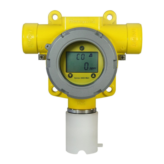
4. Introduction The Series 3000 MkII gas detector is designed to detect toxic or oxygen gas hazards in Zone 1 or 2 or 21 or 22 hazardous areas in Europe and North American Class I Division 1 or 2 areas and Class II Division 1 or 2 areas. A local LCD provides gas type and concentration information and when magnetically activated enables non-intrusive one man calibration and operation. -
Page 6: Smart Sensor
The Sunshade / Deluge Deluge Cover (P/N:SPXCDSDP) is an optional accessory that may be fitted to the integral mounting plate. This accessory is designed to protect Series 3000 MkII from overheating in exposed hot and arid climates, particularly offering additional protection from thermal shock in Tropical Environments. -
Page 7: Collecting Cone
SERIES 3000 MKII TECHNICAL MANUAL S3KMKIIMAN_MAN0878_Issue 6_01/2014 Note: The spigot on the side of the weatherproof cover is supplied for bump test purposes only (see section 14.1 for further details). 4.4.6 Collecting cone The collecting cone (part number S3KCC) can be used to assist in the detection of ‘non-sticky’ gases... -
Page 8: Installation
3000E3157 shown in section 21. Warnings Series 3000 MkII is designed for installation and use in Zone 1 or 2 or 21 or 22 hazardous areas in Europe and Class I Division 1 or 2 and Class II Division 1 or 2 area applications in North America. -
Page 9: Mounting And Location Of Detectors
Mount the Series 3000 MkII with the sensor pointing downwards. Integral mounting lugs (suitable for M8 bolts) are provided on the Series 3000 MkII transmitter housing for mounting the detector to a wall. An optional pipe mounting bracket (part number SPXCDMTBR) is available for mounting to a pipe / pole of diameter 20.0¬-80.0mm (0.8"... - Page 10 SERIES 3000 MKII TECHNICAL MANUAL S3KMKIIMAN_MAN0878_Issue 6_01/2014 164mm (6.4”) 108mm (4.2”) 99mm (3.9”) Diagram 5: Pipe Mounting Outline Dimensions 99mm (3.9”) 164mm (6.4”) Diagram 6: Wall Mounting Outline Dimensions...
-
Page 11: Electrical Connections
Warnings Series 3000 MkII is designed for installation and use in Zone 1 or 2 or 21 or 22 hazardous areas in Europe and Class I Division 1 or 2 and Class II Division 1 or 2 area applications in North America. -
Page 12: Detector Wiring Schematic
SERIES 3000 MKII TECHNICAL MANUAL S3KMKIIMAN_MAN0878_Issue 6_01/2014 6.1 Detector wiring schematic Caution: All electrical connections should be made in accordance with any relevant local or national legislation, standards or codes of practice. Detector Supply V • 17Vdc (+/-10%) < V <... -
Page 13: Terminal Connections
SERIES 3000 MKII TECHNICAL MANUAL S3KMKIIMAN_MAN0878_Issue 6_01/2014 6.3 Terminal connections All electrical connections are made at the terminal module. To access the terminal module follow the procedure below: 1. Remove the detector’s cover by unscrewing it in a counter-clockwise direction. - Page 14 SERIES 3000 MKII TECHNICAL MANUAL S3KMKIIMAN_MAN0878_Issue 6_01/2014 When all electrical connections have been made, refit the display module and cover using the procedure below: 1. Ensure that none of the wires in the terminal area may cause an obstruction. 2. Align the display module plug with the socket on the terminal module.
-
Page 15: First Time Switch On
SERIES 3000 MKII TECHNICAL MANUAL S3KMKIIMAN_MAN0878_Issue 6_01/2014 7. First time switch on After mounting and wiring the transmitter, the plug in sensor should be fitted and the installation visually and electrically tested as below. WARNING Prior to carrying out any work ensure local and site procedures are followed. -
Page 16: Magnetic Switch Activation
S3KMKIIMAN_MAN0878_Issue 6_01/2014 8. Magnetic switch activation Series 3000 MkII uses magnetic switches to enable non-intrusive operation. To activate a magnetic switch, hold the magnet up to the glass window directly over the magnetic switch area. The switch is activated when you then remove the magnet. For example: to put the detector into Menu Mode hold the magnet over the ‘’... -
Page 17: Default Configuration
S3KMKIIMAN_MAN0878_Issue 6_01/2014 8.1 Default configuration Series 3000 MkII detectors are supplied with a default configuration as shown below. The settings for full scale range, calibration gas level, calibration interval, inhibit current & timeout and access password can be changed to suit individual applications. -
Page 18: Calibration
If no residual gas is present then the background air can be used to perform the zero calibration. Contact your Honeywell Analytics representative for details of suitable calibration kits. To calibrate the detector follow the procedure below. - Page 19 SERIES 3000 MKII TECHNICAL MANUAL S3KMKIIMAN_MAN0878_Issue 6_01/2014 4. Put the magnet over the ‘’ switch and remove to enter the Calibration menu. 5. The display will show the current gas reading, ‘ZEro’ and the ‘ ’ icon flashes. 6. When the zero gas reading is stable use ‘ to confirm zero calibration.
- Page 20 SERIES 3000 MKII TECHNICAL MANUAL S3KMKIIMAN_MAN0878_Issue 6_01/2014 Display in turn Display in turn Display in turn Toggle by Up/Down Key Toggle by Up/Down Key Toggle by Up/Down Key Display in turn Toggle by Up/Down Key Display in turn Toggle by Up/Down Key 17.
-
Page 21: Zeroing And Span Calibration Of Hydrogen Sulfide Sensors
SERIES 3000 MKII TECHNICAL MANUAL S3KMKIIMAN_MAN0878_Issue 6_01/2014 8.2.2 Zeroing and span calibration of Hydrogen Sulfide sensors Hydrogen Sulfide sensors can be affected by extreme humidity changes. A sudden increase in ambient humidity can result in a short-term positive drift in the instrument’s reading. A sudden decrease in ambient humidity can result in a short-term negative drift in the instrument’s reading. -
Page 22: Display And User Interface
Warning / Fault that has been rectified. Gas Type Series 3000 MkII can be fitted with different sensors to measure 15 different gases. So the user can identify which gas the detector is measuring, it shows the gas formula of the sensor fitted on the display. - Page 23 SERIES 3000 MKII TECHNICAL MANUAL S3KMKIIMAN_MAN0878_Issue 6_01/2014 Inhibit icon ( The inhibit icon displayed when in the configure inhibit, bump test and force current menu modes. Warning / Fault icon ( The warning / fault icon is displayed if a warning or fault is detected and if a zero or span calibration fails.
-
Page 24: Monitoring Mode
SERIES 3000 MKII TECHNICAL MANUAL S3KMKIIMAN_MAN0878_Issue 6_01/2014 10. Monitoring mode After power up and successful completion of the start up routine the detector will enter monitoring mode. The detector display shows gas type and measuring units that it is configured for and the current gas reading (e.g. -
Page 25: Menu Mode Operation Table
SERIES 3000 MKII TECHNICAL MANUAL S3KMKIIMAN_MAN0878_Issue 5_07/2013 12.1 Menu mode operation table Menu mode allows the user to perform calibration and configure parameters such as full scale range, calibration gas level, calibration interval, inhibit current & timeout and set a password. To activate menu mode hold the magnet over the MENU/ENTER switch for at least 5 seconds and then remove. -
Page 26: Detector Fault / Warning Message Display
13.2 Reflex™ cell fault diagnosis Series 3000 MkII employs the patented Reflex™cell fault diagnosis routine. Reflex™ checks for cell presence, cell dry out and cell open or short circuit. In the event of an electrochemical cell failing this test, the sensor fault code is displayed. -
Page 27: General Maintenance
Note: It is recommended that the system is visually and functionally checked regularly to ensure correct operation. The frequency of the checks should be determined subject to particular site conditions. As a guide Honeywell Analytics recommend the following checks and frequency. Frequency... -
Page 28: Detector Operational Life
SERIES 3000 MKII TECHNICAL MANUAL S3KMKIIMAN_MAN0878_Issue 6_01/2014 14.2 Detector operational life Typical life of a toxic gas sensor is dependant on the application, frequency and amount of gas exposure. Under normal conditions (3 monthly visual inspection and 6 monthly test/re-calibration) the toxic sensor has an expected life equal to or greater than the lifetime as listed below: 18 months for chlorine and chlorine dioxide sensors. -
Page 29: Servicing
Disposal should be according to local waste management requirements and environmental legislation. Alternatively, sensors may be securely packaged and returned to Honeywell Analytics clearly marked for environmental disposal. Sensors should NOT be incinerated as they may emit toxic fumes. - Page 30 SERIES 3000 MKII TECHNICAL MANUAL S3KMKIIMAN_MAN0878_Issue 6_01/2014 Transmitter Old Sensor New Sensor Sensor Retainer & Locking Screw Diagram 13: Replacing Plug In Sensor...
-
Page 31: Serviceable Sensor Cell Replacement
SERIES 3000 MKII TECHNICAL MANUAL S3KMKIIMAN_MAN0878_Issue 6_01/2014 15.2 Serviceable sensor cell replacement Caution: For toxic sensors, remove the shorting clip from the bottom of the sensor prior to installation. For O2 sensor, there is no shorting clip provided. Caution: There are two types of sensor cap - teflon coated (black) and stainless steel. -
Page 32: Remote Sensor Mounting Kit Installation Details
SERIES 3000 MKII TECHNICAL MANUAL S3KMKIIMAN_MAN0878_Issue 6_01/2014 16. Remote sensor mounting kit installation details Cautions: Take care not to cut the cable too short. Once cut, additional lengths of cable cannot be added as this will invalidate the I.S certification. We also recommend that a loop of cable is made at the junction box to allow slack for any future re-termination. - Page 33 SERIES 3000 MKII TECHNICAL MANUAL S3KMKIIMAN_MAN0878_Issue 6_01/2014 9. Fit the terminal box lid. 10. Plug the sensor into the socket at the bottom of the terminal box. 11. Fit the sensor retainer, tighten the locking screw and fit the weather proof cover.
-
Page 34: General Specifications
SERIES 3000 MKII TECHNICAL MANUAL S3KMKIIMAN_MAN0878_Issue 6_01/2014 17. General specifications Series 3000 MkII Detector Rugged and reliable gas detector for the protection of personnel from toxic and oxygen gas hazards. Suitable for use in European Zone 1 or 2 or 21 or 22 hazardous areas and North American Division 1 or 2 areas. -
Page 35: Ordering Information
Inmetro approved Series 3000 MkII toxic and oxygen transmitter, Stainless Steel 316 and 2 x 3/4"NPT Entries Series 3000 MkII transmitter is supplied complete with integral wall mounting lugs, 2 x M20 or 3/4"NPT (certification dependent) entries, 1 x hex wrench set, weatherproof cap, operating magnet, test certificate and instruction manual. -
Page 36: Warranty / Liability Statement
Defective goods must be returned to Honeywell Analytics premises accompanied by a detailed description of any issue. Where return of goods is not practicable Honeywell Analytics reserves the right to charge for any site attendance where any fault is not found with the equipment. Honeywell Analytics shall not be liable for any loss or damage whatsoever or howsoever occasioned which may be a direct or indirect result of the use or operation of the Contract Goods by the Buyer or any Party. -
Page 37: Ce Certificates
SERIES 3000 MKII TECHNICAL MANUAL S3KMKIIMAN_MAN0878_Issue 6_01/2014 20. EC Declaration of Conformity A full EC declaration of conformity is available on the CD accompanying the product. This document lists the European Standards with which the Series 3000 MKII complies. -
Page 38: Certification
ATEX / IECEx Special Conditions of Use S3KX***** Series EC Cartridges When installed in the Series 3000 MkII Transmitter, the Transmitter's Tamb rating of -20°C to +55°C must be observed. When the Cartridge is installed remotely using the S3KRMK, a Tamb of -40°C to +55°C is permissible however "W03 Sensor Operating Limits Exceeded”... - Page 39 SERIES 3000 MKII TECHNICAL MANUAL S3KMKIIMAN_MAN0878_Issue 6_01/2014 21.1 UL/CSA control drawing...
-
Page 40: Ul/Csa Control Drawing
SERIES 3000 MKII TECHNICAL MANUAL S3KMKIIMAN_MAN0878_Issue 6_01/2014 21.2 Sensor Cartridge and Remote Sensor Accessory control drawing... - Page 41 S3KMKIIMAN_MAN0878_Issue 6_01/2014 21.3 Main unit UL/CSA hazardous area nameplate Honeywell Series 3000 MkII Honeywell Analytics Ltd. Poole, Dorset, UK BH17 0RZ Gas Detector for use in Haz. Loc. as to Fire, Electrical Shock and Explosion Hazards Only. Associated Apparatus - Read manual and install as per Control Dwg 3000E3160.
-
Page 42: Main Unit Ul/Csa Hazardous Area Nameplate
J.Y.JIN Honeywell Model # S3KRMK Remote Sensor Accessory Honeywell Inc. Miramar, FL, USA 33025 (optional) Honeywell Analytics Ltd, Poole, Dorset, UK BH17 0RZ GAS DETECTOR FOR USE IN HAZARDOUS LOCATIONS ONLY AS TO INTRINSIC SAFETY Honeywell Model # S3KRMK Remote Sen Intrinsically Safe for use in Class I, Division 1, Groups A, B, Honeywell Inc. - Page 43 Tel: +1 847 955 8200 Toll free: +1 800 538 0363 Fax: +1 847 955 8210 [email protected] Asia Pacific Honeywell Analytics Asia Pacific #701 Kolon Science Valley (1) 43 Digital-Ro 34-Gil, Guro-Gu Seoul 152-729 Korea Tel: +82 (0)2 6909 0300...