
Related Manuals for KitchenAid KFGR270LSS


Summary of Contents for KitchenAid KFGR270LSS
- Page 1 KAC-32 TECHNICAL EDUCATION OUTDOOR GAS GRILL Models: KFGR270LSS, KFGR274LSS, KFGR292LSS, KFGR364LSS, KBGN274LSS, KBGN292LSS, KBGN364LSS JOB AID 4317333...
- Page 2 FORWARD This KitchenAid Job Aid, “Outdoor Gas Grill,” (Part No. 4317333), provides the technician with information on the operation and service of the Outdoor Gas Grill. It is to be used as a training Job Aid and Service Manual. For specific information on the model being serviced, refer to the “Use and Care Guide”...
-
Page 3: Table Of Contents
TABLE OF CONTENTS Page GENERAL ..........................1-1 Safety First ........................1-1 KitchenAid Model & Serial Number Designations ............1-3 Model & Serial Number Label Location ................1-4 Specifications ........................1-5 Warranty .......................... 1-8 INSTALLATION INFORMATION ................... 2-1 Location Requirements ....................2-1 Important Safety Instructions ................... - Page 4 — NOTES — - iv -...
-
Page 5: General
GENERAL SAFETY FIRST Your safety and the safety of others is very important. We have provided many important safety messages in this Job Aid and on the appliance. Always read and obey all safety messages. This is the safety alert symbol. This symbol alerts you to hazards that can kill or hurt you and others. - Page 6 WARNING The California Safe Drinking Water and Toxic Enforcement Act requires the Gover- nor of California to publish a list of sub- stances known to the State of California to cause cancer, birth defects, or other repro- ductive harm, and requires businesses to warn of potential exposure to such sub- Burn Hazard stances.
-
Page 7: Kitchenaid Model & Serial Number Designations
KITCHENAID MODEL & SERIAL NUMBER DESIGNATIONS MODEL NUMBER MODEL NUMBER INTERNATIONAL SALES IND. OR MARKETING CHANNEL IF PRESENT BRAND KITCHENAID PRODUCT IDENTIFICATION FG = FREESTANDING GRILL BG = BUILT-IN GRILL MERCHANDISING SCHEME R = L.P. GAS (CONVERTIBLE) N = NATURAL GAS (CONVERTIBLE) -
Page 8: Model & Serial Number Label Location
MODEL & SERIAL NUMBER LABEL LOCATION The Model/Serial Number label location is shown below. NOTE: The label is located behind the control panel. You must remove the smoker tray to read the label. Model & Serial Number Location (Located Behind The Control Panel) -
Page 9: Specifications
SPECIFICATIONS Model Number KFGR270LSS KFGR274LSS KFGR292LSS Size 27" 27" 39" Description Portable (FS) Portable (FS) Portable (FS) Features Stainless Steel / 2 piece grill rack - welded Stainless Steel / 2 piece grill rack - welded Stainless Steel / 2 piece grill rack - welded Grates 3/8"... - Page 10 Model Number KFGR364LSS KBGN274LSS Size 36" 27" Description Portable (FS) Built-In Features Stainless Steel / 2 piece grill rack - Stainless Steel / 2 piece grill rack - welded Grates welded 3/8" rod. Bar grates. Grill rods 3/8" rod. Bar grates. Grill rods are thick, are thick, heavy and closely spaced heavy and closely spaced Yes - with divider in SS for preventing...
- Page 11 Model Number KBGN292LSS KBGN364LSS Size 39" 36" Description Built-In Built-In Features Stainless Steel / 2 piece grill rack - welded Stainless Steel / 2 piece grill rack - welded Grates 3/8" rod. Bar grates. Grill rods are thick, 3/8" rod. Bar grates. Grill rods are thick, heavy and closely spaced heavy and closely spaced Storage cabinet...
-
Page 12: Warranty
F. Replacement parts or repair labor costs for units operated outside the United States and Canada. G. Repairs to parts or systems caused by unauthorized modifications made to the grill. KITCHENAID AND KITCHENAID CANADA DO NOT ASSUME ANY RESPONSIBILITY FOR INCIDEN- TAL OR CONSEQUENTIAL DAMAGES. -
Page 13: Installation Information
INSTALLATION INFORMATION LOCATION REQUIREMENTS Select a location that provides minimum expo- WARNING sure to wind and traffic paths. The location should be away from strong draft areas. Do not obstruct flow of combustion and venti- lation air. WARNING Explosion Hazard Do not store fuel tank in a garage or indoors. -
Page 14: Important Safety Instructions
IMPORTANT SAFETY INSTRUCTIONS Inspect the gas cylinder supply hose be- FOR YOUR SAFETY fore each use of the grill. If the hose shows If you smell gas: excessive abrasion or wear, or is cut, it MUST be replaced before using the grill. 1. - Page 15 16. The pressure regulator and hose assem- IMPORTANT: This grill is manufactured for bly supplied with the outdoor gas grill must outdoor use only. be used. Replacement pressure regulator For grills that are to be used at elevations and hose assembly part number listed in above 2000 feet, orifice conversion is re- the “lnstallation Instructions.”...
-
Page 16: Product Dimensions
PRODUCT DIMENSIONS PORTABLE & BUILT-IN MODELS A minimum of 12″ (30.5 cm) must be main- tained between the grill hood, sides and back, Clearance to combustible construction for and any combustible construction. A 12″ (30.5 built-in (non-combustible construction) and cm) minimum clearance must also be main- portable grills: tained below the cooking surface and any combustible construction. - Page 17 BUILT-IN INSTALLATION WARNING (NON-COMBUSTIBLE ENCLOSURE) Enclosure and clearance dimensions that are shown must be used. Given dimensions provide required clearances. The installation of this grill must conform with the current standards CSA-Z21.58a-1998*, or Fire Hazard with local codes. Do not install this grill on or near For installations in a non-combustible enclo- combustible materials.
-
Page 18: Gas Supply Requirements
GAS SUPPLY REQUIREMENTS Observe all governing codes and ordi- PORTABLE GRILLS nances. IMPORTANT: Grill must be con- L.P. Gas nected to a regulated gas supply. This grill is equipped for use with an L.P. gas • Input ratings shown on the model/se- fuel tank. - Page 19 BUILT-IN GRILLS (NON- L.P. Gas Conversion From A Local L.P. Gas Supply COMBUSTIBLE CONSTRUCTION) Conversion must be made by a qualified Natural Gas: gas technician. The qualified natural gas tech- Built-in grill models are equipped for use with nician shall provide the L.P. gas supply to the Natural gas.
-
Page 20: Rotisserie Electrical Requirements
ROTISSERIE ELECTRICAL REQUIREMENTS Recommended Ground Method WARNING A grounded 3-prong outdoor outlet grounded in accordance with the National Electrical Code ANSI/NFPA 70**, or Canadian Electrical Code (C22.1*)—and local codes and ordinances. 3-Prong Polarized Ground- Type Outdoor Outlet Electrical Shock Hazard 3-Prong Plug into a grounded 3-prong outlet. -
Page 21: Converting To Natural Or L.p. Gas
CONVERTING TO NATURAL OR L.P. GAS Gas conversion must be done by a qualified NATURAL GAS ORIFICES installer. The Natural Gas Conversion Kit orifices are as follows: WARNING (2) #50 (Infrared Burners) (4) #44 (Grill Burners) (2) #66 (Smoker Burners) (1) Convertible Regulator Assembly (4″... - Page 22 b) Remove the infrared burner orifice and To convert the smoker burner: replace it with the proper conversion a) Remove the grill burners from the grill orifice (#50/NAT or #57/L.P.). (see step 2 on page 4-8 for the proce- dure). b) Remove the two screws from the smoker burner bracket.
- Page 23 To replace the gas regulator: e) For L.P. To Natural Gas Only: - Remove the brass elbow from the a) Remove the four screws from the rear manifold. panel and remove the panel. - Connect the natural gas regulator to the manifold.
-
Page 24: Low Flame Adjustment
GAS HOOKUP & LEAK CHECK Replace the burner sear plates and grates. Ignite the burners and check the flames. For Natural Gas: Connect a certified 1/2″ gas supply pipe to the inlet side of the Repeat Steps 1 through 8, if needed. Only regulator from a natural gas supply, ac- adjust the burners that need adjustment. - Page 25 FINAL ASSEMBLY In the last page of the owners manual, write the type of conversion you performed. Allow the burners to cool. Also record the conversion date and the Replace the burner cover, sear plates, technician/company that performed the grates, smoker tray, and access cover. conversion.
- Page 26 — NOTES — 2-14...
-
Page 27: Product Operation
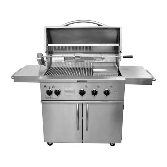
PRODUCT OPERATION FEATURES Infrared (IR) Burner Fold-Away Shelf Ignition Switch Removable 9-Volt Battery Grease Tray Compartment Smoker Tray Large Storage Area Heavy Duty Locking Casters Typical Carted Model Shown Not All Features Are Available On All Models... - Page 28 Stainless Steel Construction—The outdoor Direct Or Indirect Cooking—Sear food di- grill is constructed of welded stainless steel. rectly over the heat source, or indirectly cook the food by utilizing reflected heat. As the heat Carted Or Built-In Models—The grill is fully rises, it reflects off the lid and the inside sur- assembled for immediate use, and is available faces, and slowly cooks the food evenly on all...
-
Page 29: Lighting The Grill
LIGHTING THE GRILL PREPARE THE GAS SUPPLY IMPORTANT: Light only one burner at a time. Do not lean over the burners. Push in and Open the hood completely. Do not light the turn to “LITE” the control knob for the burners with the hood closed. - Page 30 5 minutes before relighting. Carefully hold the lit match close to the If any burners do not light after attempting to infrared burner. manually light them, contact the KitchenAid Assistance Center. LIGHTING THE INFRARED (IR) ROTISSERIE BURNER Push in and turn the rotisserie burner knob to “LlTE.”...
- Page 31 MANUALLY LIGHTING THE Carefully guide the lit match into the smoker chamber area where the tray was re- SMOKER BURNER moved. WARNING Burn Hazard Do not remove the smoker box when Push in and turn the knob for the smoker the grill is hot.
- Page 32 — NOTES —...
-
Page 33: Component Access
COMPONENT ACCESS This section instructs you on how to service each component inside the Outdoor Gas Grill. The grill components and their locations are shown below. COMPONENT LOCATIONS (TYPICAL) Infrared Burner Ignitor & Thermocouple Infrared Burner Smoker Burner Burner Baso Gas Smoker Burner Smoker Burner 9-Volt Battery... -
Page 34: Removing The Control Panel, Spark Module, And Ignition Switch
REMOVING THE CONTROL PANEL, SPARK MODULE, AND IGNITION SWITCH To remove the control panel: Turn off and disconnect the gas supply going to the grill. a) If you are replacing the control panel, not just removing it, remove the two Pull the knobs off the gas valves. - Page 35 To remove a spark module: To remove the ignition switch: a) Loosen (do not remove) the two spark a) Remove the bezel nut from the control module screws (see the photo in step panel and remove the switch. 5b on page 4-2). b) Remove the cover from the spark mod- ule.
-
Page 36: Removing The Infrared Burner Ignitor & Thermocouple
REMOVING THE INFRARED BURNER IGNITOR & THERMOCOUPLE Turn off and disconnect the gas supply c) Remove the screws from the rear panel going to the grill. and remove the panel. Infrared Burner Ignitor & Thermocouple Screw (1 of 4) Rear Panel d) Remove the screw from the infrared burner ignitor &... - Page 37 To remove the thermocouple: c) Remove the rear panel and the infrared burner ignitor & thermocouple cover a) Remove the control panel (see page (see steps 2c and 2d on page 4-4). 4-2 for the procedure). d) Push the thermocouple out of its hold- b) Unscrew the thermocouple connector ing clip.
-
Page 38: Removing The Infrared Burner
REMOVING THE INFRARED BURNER Turn off and disconnect the gas supply Remove the screw from the rear access going to the grill. panel and remove the panel. Remove the infrared burner ignitor from Rear Access Panel the grill (see step 2 on page 4-4 for the procedure). - Page 39 Push the thermocouple out of its holding Remove the burner grates and griddle, if clip and position it in the access opening. installed. Thermocouple Out Of Clip Remove the three screws from the front of the infrared burner panel, then pull the front of the panel forward, and remove the burner panel from the unit.
-
Page 40: Removing A Burner, Burner Ignitor, Baso Gas Valve, And Burner Gas Valve
REMOVING A BURNER, BURNER IGNITOR, BASO GAS VALVE, AND BURNER GAS VALVE Turn off and disconnect the gas supply b) Lift the rear of the burner, pull the air going to the grill. shutter off the gas valve orifice, and remove the burner. - Page 41 To remove a burner ignitor: d) Remove the screw from the ignitor bracket and collector box. NOTE: Hold a) Remove the grates, the griddle (if in- the collector box while removing the stalled), and the sear plates. screw since the screw secures both the b) Remove the control panel and the spark ignitor and the collector box.
- Page 42 To remove the baso gas valve: To remove a burner gas valve: a) Remove the control panel (see page a) Remove the control panel (see page 4-2 for the procedure). 4-2 for the procedure). b) Remove the thermocouple and gas line b) Remove the two 5/8″...
-
Page 43: Removing The Smoker Burner And Gas Valve
REMOVING THE SMOKER BURNER AND GAS VALVE c) Remove the two screws from the rear WARNING burner rail and move the rail to the rear of the burner box. Screw Screw Rear Burner Rail Burn Hazard Do not remove the smoker box when the grill is hot. - Page 44 f) Remove the slotted end of the smoker c) Remove the flex gas line connector burner from the opening in the rear from the smoker burner gas valve. burner rail. d) Unscrew the smoker burner gas valve from the manifold. Smoker Burner Gas Valve Slotted End Of Smoker Burner...
-
Page 45: Removing The 9-Volt Battery
REMOVING THE 9-VOLT BATTERY To remove the 9-volt battery: b) Pull the battery holder out of the control panel. a) Pull the battery holder cover out at the c) Remove the battery from the holder bottom to release the magnetic seal. and unclip the connector from the bat- tery terminals. -
Page 46: Removing A Cabinet Door
REMOVING A CABINET DOOR To remove the cabinet door, open the door. Lift the door straight up, and unhook the hinge pins from the hinge hangers. Lift Door Straight Up 4-14... -
Page 47: Product Specifications
WARRANTY INFORMATION SOURCES IN THE UNITED STATES: FOR PRODUCT SPECIFICATIONS AND WARRANTY INFORMATION CALL: FOR WHIRLPOOL PRODUCTS: 1-800-253-1301 FOR KITCHENAID PRODUCTS: 1-800-422-1230 FOR ROPER PRODUCTS: 1-800-447-6737 FOR TECHNICAL ASSISTANCE WHILE AT THE CUSTOMER’S HOME CALL: THE TECHNICAL ASSISTANCE LINE: 1-800-253-2870...