Yamaha F-20B Service Manual
Hide thumbs
Also See for F-20B:
- Owner's manual (92 pages) ,
- Installation manual (12 pages) ,
- Owner's manual (90 pages)
Table of Contents
Quick Links
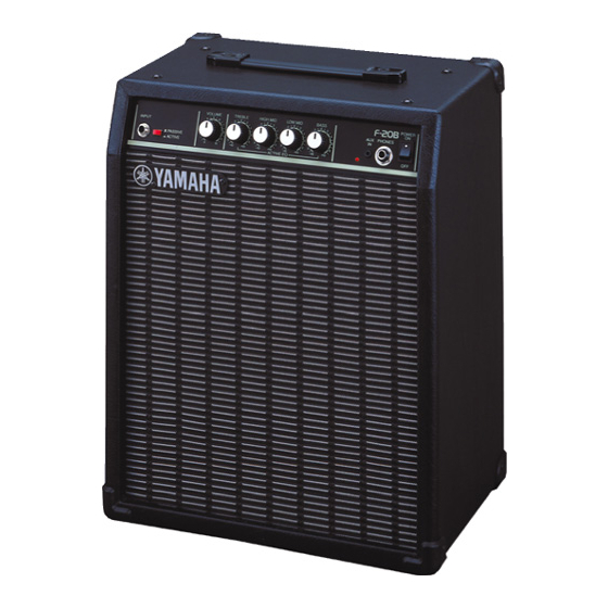
BASS AMPLIFIER
SERVICE MANUAL
CONTENTS
SPECIFICATIONS .............................................................................. 3
PANEL LAYOUT .................................................................................. 3
CIRCUIT BOARD LAYOUT ................................................................. 4
BLOCK DIAGRAM .............................................................................. 4
DISASSEMBLY PROCEDURE ........................................................... 5
CIRCUIT BOARDS ............................................................................. 7
IC BLOCK DIAGRAM .......................................................................... 8
INSPECTIONS .................................................................................... 8
This document is printed on chlorine free (ECF) paper with soy ink.
GA
011592
HAMAMATSU, JAPAN
20010720-17800
1.507K-033 K
Printed in Japan 2001.08
Table of Contents

Related Manuals for Yamaha F-20B


Summary of Contents for Yamaha F-20B
-
Page 1: Table Of Contents
BASS AMPLIFIER SERVICE MANUAL CONTENTS SPECIFICATIONS ................3 PANEL LAYOUT .................. 3 CIRCUIT BOARD LAYOUT ..............4 BLOCK DIAGRAM ................4 DISASSEMBLY PROCEDURE ............5 CIRCUIT BOARDS ................7 IC BLOCK DIAGRAM ................8 INSPECTIONS ..................8 PARTS LIST OVERALL CIRCUIT DIAGRAM This document is printed on chlorine free (ECF) paper with soy ink. -
Page 2: Important Notice
IMPORTANT NOTICE This manual has been provided for the use of authorized Yamaha Retailers and their service personnel. It has been assumed that basic service procedures inherent to the industry, and more specifically Yamaha Products, are already known and understood by the users, and have therefore not been restated. -
Page 3: Specifications
F-20B SPECIFICATIONS Rated Output Power: Speaker: 25cm x 1 Controls: VOLUME, TREBLE, HIGH MID, LOW MID, BASS, Input Level Select Switch (PASSIVE/ACTIVE) Input/Output Terminals: INPUT, AUX IN, PHONES Power Consumption: 25W/120V (UL, CSA) 25W/230V (E, BS) Power Requirements: U.S. and Canadian mod-... -
Page 4: Circuit Board Layout
F-20B CIRCUIT BOARD LAYOUT Top View Side View AC Cord MAIN Power Transformer MAIN MAIN MAIN Front View MAIN BLOCK DIAGRAM MAIN GAIN SELECT ACTIVE CH. PASSIVE CH. AUX IN +12V INPUT ACTIVE TYPE TONE CONTROL IC1,IC2 VOLUME OP AMP... -
Page 5: Disassembly Procedure
F-20B DISASSEMBLY PROCEDURE Pre-Main Unit (Time required: about 2 min) Remove the eight (8) screws marked [A]. The back board can then be removed. (Fig.1) Pull out the speaker wires. (Fig.1) Remove the four (4) screws marked [30]. The pre- main unit can then be removed by sliding it backward. - Page 6 F-20B MAIN 2/2 Circuit Board (Time required: about 3 min) Remove the pre-main unit. (See Procedure 1) Remove the screw marked [C80]. The MAIN 2/2 circuit board can then be removed. (Fig.3, Fig.5) Power Transformer (Time required: about 4 min) Remove the pre-main unit.
-
Page 7: Circuit Boards
F-20B CIRCUIT BOARDS MAIN1/2 CIRCUIT BOARD GAIN INPUT VOLUME TREBLE SELECT to POWER to POWER SW TRANSFORMER from POWER to MAIN 2/2 CN4 from AC CORD TRANSFORMER FUSE VERSION INDICATION RATE J, U 250V 315mAL Must be erased Must be... -
Page 8: Ic Block Diagram
F-20B IC BLOCK DIAGRAM BA4558 (XO078A00) Dual Operational Amplifier MAIN: IC1,IC2,IC3 +DC Voltage Output A Supply Inverting Output B Input A Non-Inverting Inverting Input B Input A Non-Inverting -DC Voltage Supply Input B INSPECTIONS Preparation To inspect the main unit, the following jigs are required. -
Page 9: Parts List
F-20B BASS AMPLIFIER PARTS LIST CONTENS OVERALL ASSEMBLY .................. 2 PRE-MAIN UNIT .................... 4 ELECTRICAL PARTS ..................6 Note) DESTINATION ABBREVIATIONS Australian model South African model British model Chinese model Canadian model South-east Asia model German model Taiwan model European model U.S.A. - Page 10 F-20B OVERALL ASSEMBLY Pre-Main Unit C100 C110 Overall Cabinet Assembly...
- Page 11 F-20B PART NO. DESCRIPTION REMARKS REF NO. QTY RANK OVERALL ASSEMBLY F-20B Overall Assembly (V745880) Overall Assembly (V745890) Overall Assembly (V745900) Overall Assembly (V745910) V 7 4 6 11 0 0 Overall Cabinet Assembly Pre-Main Unit (V745930) Pre-Main Unit (V745940)
- Page 12 F-20B PRE-MAIN UNIT A100 A110 A120 A130 A140 Amp Kit P100 P120 P110...
- Page 13 F-20B PART NO. DESCRIPTION REMARKS REF NO. QTY RANK PRE-MAIN UNIT F-20B Pre-Main Unit (V745930) Pre-Main Unit (V745940) Pre-Main Unit (V745950) Pre-Main Unit (V745960) V6954800 Chassis V7460600 Panel Sheet Amp Kit (V746070) Amp Kit (V746080) Amp Kit (V746090) Amp Kit...
- Page 14 F-20B ELECTRICAL PARTS DESCRIPTION REMARKS PART NO. QTY RANK REF NO. ELECTRICAL PARTS F-20B V 7 5 5 4 7 0 0 Circuit Board MAIN J,U,C (X0085A0) V 7 5 5 4 8 0 0 Circuit Board MAIN (X0085A0) V 7 5 5 4 7 0 0...
- Page 15 F-20B PART NO. DESCRIPTION REMARKS REF NO. QTY RANK HF456330 Carbon Resistor 3.3K 1/4 J HF457330 Carbon Resistor 33.0K 1/4 J HF457330 Carbon Resistor 33.0K 1/4 J HF458100 Carbon Resistor 100.0K 1/4 J HF457100 Carbon Resistor 10.0K 1/4 J HF457330 Carbon Resistor 33.0K 1/4 J...
-
Page 16: Overall Circuit Diagram
OVERALL CIRCUIT DIAGRAM F-20B D2SBA20 (VP344100) MAIN DIODE STACK 1.5A 200V GAIN SELECT OP AMP OP AMP OP AMP OP AMP OP AMP AUX IN INPUT BASS LOW MID HIGH MID TREBLE MAIN OP AMP OP AMP VOLUME HIFI AMP...