3M Dynatel 2250M Operator's Manual
Cable/pipe/fault advanced locator
Hide thumbs
Also See for Dynatel 2250M:
- Operator's manual (28 pages) ,
- Quick manual (2 pages) ,
- Operator's manual (20 pages)
Table of Contents

Related Manuals for 3M Dynatel 2250M


Summary of Contents for 3M Dynatel 2250M
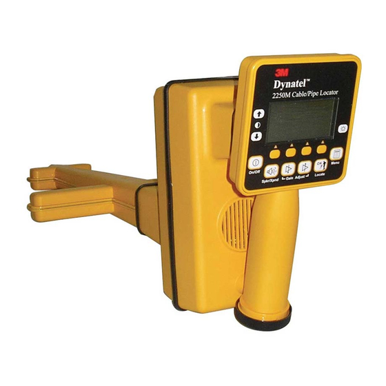
- Page 1 ® Advanced Test Equipment Rentals www.atecorp.com 800-404-ATEC (2832) Dynatel ™ ™ Cable/Pipe/Fault Advanced Locator 2250M/2273M Series (With 3-watt, 5-watt, or 12-watt Transmitter) Operator’s Manual 2250M 2250M-iD 2273M 2273M-iD June 2010 78-8130-6150-0-F...
-
Page 2: Table Of Contents
Contents 1. Safety Information .................... 6 A. Intended Use ....................6 2. About This Manual ................... 7 3. Quick Start ......................8 A. Transmitter Battery Installation ..............8 B. Receiver Battery Installation ............... 9 C. Cleaning ..................... 10 D. Service and Accessories ................10 E. 2250 Transmitter Keypad and Connector Definitions ........ 10 F. 2273 Transmitter Keypad and Connector Definitions ........ 11 G. Maximum Transmitter Output ..............12 H. Rechargeable Battery ................. 12 I. 2250M Receiver Key Pad and Display Definitions ........13 J. 2273M Receiver Key Pad and Display Definitions ........14 4. Menu Displays ....................15 A. Main Menu ....................15 5. Configuring The Receiver ................18 A. Select Depth Units .................. - Page 3 C. Passive Frequencies ................... 32 D. Auxiliary Frequencies ................32 10. Locating in Directional Peak Mode .............. 33 11. Locating Active Duct Probes (Sondes) ............35 A. Determining ADP Depth ................35 12. Locating Buried Sheath Faults and Earth-Return Faults ......36 A. Transmitter Setup ..................36 B. Pinpointing the Buried Fault ..............37 13. Locating 3M Electronic Markers and 3M iD Markers ......39 ™ ™ A. Enabling/Disabling Marker Types ............. 39 B. Alert Mode ....................39 C. Single Marker Locate ................. 40 D. Dual Marker Locate .
- Page 4 19. Additional Applications ................53 A. Aerial Faults (Toning) ................53 B. Cable Identification ..................55 20. Help Mode ....................56 21. 3M Dynatel PC Tool Kit and Locator Software Upgrades ....... 56 ™ ™ 22. Self Test Of Receiver ..................57 23. Product Description And Optional Accessories ..........57 A. Product Description ................... 57 B. Standard Configurations ................58 C. Optional 3M Dynatel Accessories ............59 ™ ™ 24. Receiver Specifications ................. 60 25. Transmitter Specifications .
- Page 5 Congratulations! You have just purchased one of the finest, most advanced locating devices available today! The 3M Dynatel Cable/Pipe/Fault Locators 2250M-iD/2273M-iD are designed with ™ ™ all of the functionality of previous Dynatel models, and iD versions have the enhanced capability to read and write user information into the 3M iD markers. Information such as a pre-programmed identification number, facility data, application type, placement date and other details can all be read, stored and downloaded to your PC for enhanced resource management with this revolutionary equipment. The Dynatel Cable/Pipe/Fault Locators 2250M-iD/2273M-iD will also search for two different types of utility markers simultaneously. When used in conjunction with a hand-held GPS device the ability to transmit path and marker coordinates multiplies the potential to the mapping industry. This equipment provides a simple system for mapping utility information directly into CAD and GIS systems. The 2250M/2273M Series transmitters are available in 3-watt, 5-watt and 12-watt units. 12 watts for the 12-watt transmitter, or 5 watts for the 5-watt transmitter, is attained by utilizing the Cigarette Lighter Adapter or External Rechargeable Battery (2200RB). 3M is dedicated to bringing you premium equipment with outstanding reliability, backed by one of the best warranties in the business and outstanding service. Visit our website at www.3M.com/dynatel for more application notes and product information. 78-8130-6150-0-F...
-
Page 6: Safety Information
WARNING If this equipment is used in a manner not specified by 3M, the protections provided by the equipment may be impaired. Explanation of Signal Word Consequences m Warning: Indicates hazardous situation which if not avoided, could result in death or serious injury. -
Page 7: About This Manual
IF THE ABOVE INSTRUCTIONS ARE NOT FOLLOWED. USE APPROPRIATE SAFETY PROCEDURES. CHECK VOLTAGE BEFORE CONNECTING TRANSMITTER. VOLTAGE HIGHER THAN 240 VOLTS WILL DAMAGE EQUIPMENT. FOLLOW STANDARD PROCEDURES FOR REDUCING THE VOLTAGE. 2. About This Manual There are two basic models included in the 3M Dynatel Locator 2200M Series. The 2250M is designed for cable/pipe locating. The 2273M is designed for cable/pipe and fault locating. The iD option (read/write capability to 3M iD Markers) is available for both models. There are three transmitter options: 3 Watt, 5 Watt, or 12 Watt. -
Page 8: Quick Start
3. Quick Start A. Transmitter Battery Installation Loosen the six screws on the battery compartment cover on the bottom of the transmitter. Remove the cover. Install six ‘C’ size alkaline cell batteries (LR14) into the compartment as indicated by the polarity symbols (+ and –). Replace the cover and tighten the screws. 6 'C' (LR14) size Alkaline Batteries Press and hold OFF [T-1] to manually test the batteries. The display and audio will indicate one of the following levels: (OK w/solid tone = good; LO w/beeping tone = low; "--" w/no tone = replace) m Caution To reduce the risks associated with fire and explosion: • Do not short, excessively heat, or dispose of batteries in fire. •... -
Page 9: Receiver Battery Installation
B. Receiver Battery Installation Remove cap from receiver handle. Install eight ‘AA’ size alkaline cell batteries (LR6) into the battery holder as indicated by the polarity symbols (+ and –). Attach battery holder to the PP3 connector in the receiver handle, and slide holder into the handle. Replace the cap. 8 “AA” (LR6) Alkaline Batteries 1. Twist cap to open battery compartment. 2. Slide battery compartment out of handle. m Caution To reduce the risks associated with fire and explosion: • Do not short, excessively heat, or dispose of batteries in fire. •... -
Page 10: Cleaning
C. Cleaning Use a soft damp cloth to clean the product and test leads if necessary. D. Service and Accessories Information regarding service, accessories, or replacement parts can be obtained by contacting 3M at 1-800-426-8688. This equipment does not require annual calibration or maintenance. E. 2250 Transmitter Keypad and Connector Definitions Dynatel 2250 Trace Output Level [T-1] off: Turns unit off and performs battery test. [T-2] on: Ohm-meter / Tone: Turns the unit on and cycles through the following commands when pressed repeatedly. Ohm-meter: Measures the continuity of the trace conductor/pipe and its far-end ground. It is also used to measure the fault resistance to earth. Tone: In the tone mode, the transmitter generates 577 Hz and 200 kHz signals. [T-3] on: Trace (frequency): Turns the unit on and places the unit in Trace mode. -
Page 11: 2273 Transmitter Keypad And Connector Definitions
NOTE: 12 Watt Output Level varies by frequency. Output is limited to 10 watts at 33 kHz and 1 watt at 200 kHz using the direct connection method. [T-6] Output Jack: Port for direct connect cables or Dyna-coupler. [T-7] External Jack: Port to connect cigarette lighter adapter cable, or rechargeable battery (2200RB). Input voltage level: 9-18 VDC. (Only on 5-watt and 12-watt transmitters.) F. 2273 Transmitter Keypad and Connector Definitions [T-1] off: Turns unit off and performs battery test. -
Page 12: Maximum Transmitter Output
• Voltage greater than 240 volts will damage equipment and could cause personal injury or death. Make all connections before turning on the transmitter. Follow standard procedures for reducing the voltage. • Do not change or modify this product in any way. H. Rechargeable Battery The 3M Dynatel Sealed Gel-Cell Battery 2200RB can be used as an auxiliary battery in Dynatel 2200 Series Transmitters. It plugs ™... -
Page 13: 2250M Receiver Key Pad And Display Definitions
I. 2250M Receiver Key Pad and Display Definitions Dynatel ™ 2250M Cable/Pipe Locator Access panel on bottom side of Receiver under Menu On/Off rubber cover. Spkr/Xpnd Gain Adjust Locate [1] On/Off (Power): Turns unit on and off. [2] Speaker Volume Control: Adjusts the volume of the receiver (off, low, med, high, and Xpand). [2A] Speaker Volume Icon: Indicates the relative volume level of the receiver. When the third ring is dotted and ‘xpnd' appears below the speaker icon, the receiver is in “Expander” mode. This mode is used to pinpoint the target cable or pipe. -
Page 14: 2273M Receiver Key Pad And Display Definitions
[15] Earphone Jack: Will fit standard 1/8" (3.175 mm) mini-jack mono earphone plug (not included). J. 2273M Receiver Key Pad and Display Definitions Access panel on bottom side of Receiver under rubber cover. [1] On/Off (Power): Turns unit on and off. [2] Speaker Volume Control: Adjusts the volume of the receiver (off, low, med, high, and Xpand). [2A] Speaker Volume Icon: Indicates the relative volume level of the receiver. When the third ring is dotted and ‘xpnd' appears below the speaker icon, the receiver is in “Expander” mode. This mode is used to pinpoint the target cable or pipe. [3] Contrast: The arrows located above and below the contrast icon will adjust the contrast of the display. -
Page 15: Menu Displays
[13] Fault Finding Direction Indicators: Corresponds to the Earth Contact Frame (A-Frame) probe (leg) colors. [l4] External Jack: Port to connect cables from external devices such as the earth frame (A-Frame), a second Dyna-Coupler, or a toning coil. [15] Serial Port: RS232 port to connect the receiver to a PC via serial cable or USB-to- serial adapter cable. [16] Earphone Jack: Will fit standard 1/8" (3.175 mm) mini-jack mono earphone plug (not included). 4. Menu Displays A. Main Menu When the Menu [6] button is pressed, the Main Menu display appears. The function appears on the display above each soft key. Write Mode: System used to write information to iD Markers Data/Template: Displays marker history and template creation/selection displays: a. Read History – 100 memory locations for Read iD Markers b. -
Page 16
COM Setup: Displays second level COM Port setting display to configure RS232 port communication with different devices – a. PC – Receiver will communicate to a computer b. NMEA – Port is configured to accept coordinates from GPS device c. GIS – Port is configured to send iD marker information or path information to GPS device and receive coordinates from GPS device. d. PDA – receiver will send iD marker and path information in ASCII string. >>More: Advances to next menu display <
- Page 17 e. <
>More - Advances to next menu display i. < Page 18: Configuring The Receiver
1. Press the left/right arrow [SK] to highlight the digit of the date or time to change. 2. Press the + or - [SK] to increment or decrement. 3. When the date format is highlighted, the format will toggle between mm/dd/yy and dd/mm/yy. 4. Press Locate/OK [5] to save, or Menu [6] to cancel. C. Selecting a Language MENU [6] + >>More [SK:4] + Setup [SK:6] + Lang [SKToggle:6c] The soft key command will cycle through available languages. Press Locate/OK [5]. Alternate languages can be uploaded to the receiver using the Dynatel PCTools ™ software. The 3M Dynatel PC Tool Kit software is available free of charge at ™ ™ www.3M.com/dynatel under the Software section; 2550/2573/2250M/2273M/1420 Locator PC Tools xx.x.x (EXE xx.xMB). 78-8130-6150-0-F...Page 19: Enabling/Disabling Frequencies
D. Enabling/Disabling Frequencies MENU [6] + >>More [SK:4] + Setup [SK:6] + >>More [SK:6d] + Locate Freq [SK:6g] The user can select the frequencies that the receiver will detect. All the available frequencies are listed in four groups (Left to Right: Active, Power, Passive, and Auxiliary). The Auxiliary group also contains the User Defined Frequencies. (See Creating User Defined Frequencies, Section 5F.) 1. Press the right arrow [SK] to move the highlight bar to the section of frequencies to enable, or disable. 2. Press the up/down arrows [SK] to highlight the specific frequency. 3. Press Enabl/Disabl [SK]. (Enable denoted by 3) 4. Repeat steps 2 & 3 to enable/disable other frequencies. 5. Press Locate/OK [5] to save. E.Page 20: Filtering Power Frequency Interference
To program the user defined frequencies press the right arrow [SK] to highlight the Auxiliary group of frequencies. Press the up/down arrows [SK] to highlight the user frequency to program. Press Enabl/Disabl [SK]. Press the left/right arrows [SK] to move the square cursor to a digit. Press Select [SK] to enter the number in the frequency field. Press Locate/OK [5] to save the programmed frequency, or press Exit [SK] to cancel. The frequency will appear in the locate frequency display as U ###, where ### represents the selected frequency. Note: To redefine a previously programmed user frequency, highlight the frequency, press enabl/ disabl, select the back arrow with the cursor, and press select to delete the previous entry. G.Page 21: Buried Cables And Pipes: Transmitter Connections
6. Buried Cables And Pipes: Transmitter Connections Perform a battery test. Use one of the following three methods to produce a trace signal on the target pipe or cable. A. Direct Connect Method m WARNING This WARNING applies to the use of the Direct Connect Cables and the Transmitter. To avoid potential shock, or electrically damaging the Transmitter, when setting up the Transmitter to locate using the Direct Connect method, follow these basic steps;...- Page 22 2. Turn the transmitter on by pressing Ohms [T-2]. The continuity of the circuit will be measured. The results are displayed [T-4] in ohms and as a tone. − If the continuity of the circuit is very good (the reading on the display is less than 3K Ω. and a solid tone from the transmitter is heard) all frequencies can be used to locate. Always use the lowest frequency available (for example, 577 Hz). Lower frequencies are less likely to ‘bleed over’ to other cables in the same area, and are very good for tracing over long distances. − If the circuit reads more than 3K Ω., but less than lOK Ω (indicated by a beeping tone from the transmitter) it will be necessary to use a higher frequency than 577 Hz in order to locate the cable/pipe. − If the circuit reads more than lOK Ω., it will be necessary to use an RF signal such as 33 kHz or 200 kHz. − If there is no tone and the transmitter indicates that there is an open circuit (OL in the display) this could be an indication of a poor ground, or an open-ended cable or pipe. Use one of the higher frequencies available, at high or maximum output power level. If it is an open-ended cable or pipe, the receiver's response will decrease suddenly at the site of the clear or severed end. Note: In the ohms mode, the transmitter can detect voltage as well as ohms. If a low voltage is detected, the display will alternate between displaying ohms and volts. When displaying ohms, the flag over the Ω...
Page 23: Dyna-Coupler Method
B. Dyna-Coupler Method m WARNING This WARNING applies to the following 3M Dyna-Couplers; • 3" (75 mm) - Part number 3001 • 4.5" (114 mm) - Part number 4001 • 6" (150 mm) - Part number 1196 • All accessory kits containing any of the listed Dyna-Couplers - Part numbers 3019, 4519,...Page 24: Induction Method
C. Induction Method If you cannot make a direct connection, or use the 3M Dynatel Dyna-Coupler clamp to ™ ™ apply a locating signal on the target, use the induction method. When nothing is plugged into the Output Jack [T-6] of the transmitter the unit will be placed into induction mode when it is turned on. This method uses the internal coil of the transmitter to generate a magnetic field. This is the least preferred method of applying a signal on a target conductor because it can easily be picked up by other non-target conductors in the area. However, it is the preferred method of applying a signal to multiple cables/pipes in the same trench, and for the ‘two-person sweeping’ application. 3M Dynatel transmitters provide a choice of induction frequencies and output power levels. Higher induction output power levels are needed for detecting deeper depths and longer ranges. The 2200M Series 3 Watt transmitters provides two induction frequencies: 33 kHz and 200 kHz. The 12 Watt transmitter provides three induction frequencies: 8 kHz, 33 kHz and 200 kHz. The 200 kHz frequency is commonly used for deeper cables/ pipes and the lower frequencies are used to give longer locate distances. The 8 kHz (low frequency) induction helps in locating shallow facilities, such as risers (12 Watt transmitter only.) The following sections review Non-sweeping and Sweeping (Area) methods used with the Induction Mode. The Non-Sweeping method is utilized when a specific target requires path tracing. The transmitter remains stationary in-line over the target and the path is traced. The Sweeping method is utilized when a designated area needs to be swept for non-specific targets, for example, all the buried pipes or conductors in the designated area. Several sweeping methods will be reviewed. A. Non-Sweeping (Passive) Induction Mode Locating • Position the transmitter over the target facility, with the hinge of the transmitter over and in line with the cable/pipe path. Remove any cables from the Output Jack [T-6]. − Align the Induction Direction arrows on the transmitter with the target conductor.- Page 25 Attempting to trace the target close to the transmitter may lead to false indications due to the receiver detecting the large magnetic field radiating from the transmitter. B. Sweeping (Active) Induction Mode Locating Sweeping an area with the 3M Dynatel 2200M Series locator allows the location of multiple metallic cables and pipes buried in an area without direct connect or coupler access to the cable or pipe. This approach is effective before any excavation takes place. Note that when specific buried objects need to be identified, it's important to use the direct connect or coupler method for applying the signal. This will help limit the applied...
- Page 26 ground. Other passive sources exist, such as Cathodic Protection, LF and CATV cable (with NTSC TV CRT turned on). Walk in a grid pattern over the sweep area holding the receiver as shown in the following illustration. Stop when there is a response increase, locate the position of the maximum signal, follow the conductor path all the way out of the sweep area while putting location marks on the ground. Resume the sweep until another cable or pipe is detected, or the whole area is completely swept. Switch to another available passive frequency in the receiver and sweep again. D. One-person Active Induction Mode Sweeps One-person active induction mode sweeps require that the transmitter be set on the ground over the suspected path of the buried infrastructure. The receiver is used to detect signals induced by the transmitter on buried long conductors. Proper placement and orientation is key to maximize the induced signal in the buried cable or metallic pipe enough to be detectable by the receiver along each path in the swept area. (Note that no signal is induced onto a conductor whose path is perpendicular to the Induction Direction indication.) • Place the transmitter in the upright (bottom on ground) position for directional optimization when aligned with the Induction Direction shown on the label on the transmitter. • Tip the transmitter over towards the front, and lay it on it's front surface, for multi- directional wide area induction. (Note that no signal is induced onto a conductor whose path is directly under the transmitter). • Remove anything plugged into the Output Jack [T-6] (this will place unit in Induction Mode), select highest available frequency (200 kHz) and highest output power level. • Select the Induction Peak (Ind Pk) mode and 200 kHz frequency on the receiver. When in close proximity to the transmitter in induction mode, there is a direct signal from the induction antenna in the transmitter to the receiver through the air. Induction Peak (Ind Pk) mode is a newly added locate mode for use in closer proximity to a transmitter in Induction mode (<60 ft , 20 m typ.). Special (single) Peak (Spl Pk) would give the highest sensitivity, but is affected by the air signal more than Induction Peak (Ind Pk) mode.
- Page 27 E. Two-person Active Induction Mode Sweeps In two-person active induction mode sweeps, one person holds the transmitter and the other holds the receiver while walking together in a sweep pattern detecting long conductors in the ground when crossed by transmitter and receiver positions and orientation, as shown below: Transmitter Set-up • Remove anything plugged into the Output Jack [T-6] (this will place unit in Induction Mode), select high frequency (200 kHz), or medium frequency (33 kHz or 82 kHz), and highest output power level. • Hold the transmitter with the lid facing up and align it with the Induction Direction arrow label, as shown on the transmitter, with the receiver Receiver Set-up • Set the receiver to the same frequency as the transmitter. • Select the Induction Peak (Ind Pk) mode, and press the Gain Adjust [4] (+ or -) key until the bar graph is just visible. Sweeping • Sweeping can be done at close distances between the transmitter and receiver. • For best results, the receiver should be at least 25 feet (7.6 m) away from the transmitter to begin tracing the target path and have the gain set between 78-84% when starting the sweep. Attempting to trace the target close to the transmitter may lead to false indications due to the receiver detecting the large magnetic field radiating from the transmitter. • Induction Peak (Ind Pk) mode cancels the air signal coming directly from the transmitter induction antenna to the receiver. Increasing the sweep distance between the transmitter and receiver reduces the direct air signal and allows for sensing deeper conductors and sections of metal pipes. Use Induction Peak (Ind Pk) mode when sweeping distance between the transmitter and receiver is 25–60 feet (7.6–20...
Page 28: Receiver Modes
7. Receiver Modes A. Directional Peak (Dir Pk) Locate/OK [5] + Cable/Pipe [SK] + Mode [SK] + Dir Pk [SK Toggle] In Dir Pk mode, four peak antennas are used to analyze the magnetic field pattern. The Bar Graph [1l] indicates Signal Strength [10] and the directional arrows sense the edges of the magnetic field. The left/right arrows will indicate the direction to the nearest cable that is in-line with the receiver handle. As the antenna crosses the cable or pipe, the receiver speaker volume increases to a maximum, the Bar Graph [1l] fills from both sides toward the middle, and the numeric Signal Strength [10] increases. As the antenna moves off the target path, the speaker volume decreases and the Bar Graph [1l] opens. Use the Bar Graph [1l] and the numeric Signal Strength [10] value to locate the exact target path. Right of Target Path Left of Target Path Directly Over Target Path Once the target path has been located, the arrows at the top of the display will indicate...Page 29: Special Peak (Spl Pk)
For example: Figure 1: If the target path is to the right of the receiver, and running parallel to the operator, the right arrow will display. Figure 2: If the target path is to the left and in front of the operator (not running parallel to the receiver) the arrow will point toward the top left side of the display. Figure 3: When the receiver crosses the target path, a solid line will appear, instead of arrows, indicating the target path and its orientation to the receiver handle. Before marking target path, always use Directional Peak (Dir Pk) or Special Peak (Spl Pk) mode to verify location. C. Special Peak (Spl Pk) Locate/OK [5] + Cable/Pipe [SK] + Mode [SK] + Spl Pk [SK Toggle] Special Peak Mode turns on only the peak antenna closest to the ground. Special Peak Mode is used in applications such as very deep cables or pipes, or when the signal is too weak for directional peak tracing.Page 30: Induction Peak (Ind Pk)
D. Induction Peak (Ind Pk) Locate/OK [5] + Cable/Pipe [SK] + Mode [SK] + Ind Pk [SK Toggle] If you cannot make a direct connection, or use the 3M Dynatel Dyna-Coupler clamp ™ ™ to apply a locating signal on the target, use the induction method. This method uses the internal coil of the transmitter to generate a magnetic field. The Induction Peak mode of the receiver is a mode in which the upper antenna of the receiver is tuned to minimize distortion from the magnetic field of the transmitter. Left or Right of Target Path Directly Over Target Path E. Expanded Mode When the third ring of the speaker icon is dotted or broken and ‘xpnd’ appears below the speaker...Page 31: Locating Frequencies
− The operator may select the memory location to store the depth readings by pressing Mem Select [SK]. When the preferred location appears on the display, press Save [SK]. The display and memory location will populate with the current information. − Each memory location can be reviewed by pressing Mem Select [SK]. 5. Press Locate/OK [5] to return to Locate Mode. 9. Locating Frequencies A. Active Frequencies Active frequencies are trace signals supplied by a 3M Dynatel 2200 Series ™ ™ Transmitter (577 Hz, 8 kHz, 33 kHz, or 200 kHz). 1. Select the same frequency that the transmitter is generating. 2. Press Locate/OK [5] 3. Press Cable/Pipe [SK] 4. Press Freq [SK] 5. Press Active [SK Toggle] until the desired frequency is displayed in the soft key command [9] (“Active” 577, 8K, 33K or 200K) 6. Press Locate/OK [5] to return to Locate mode.Page 32: Power Frequencies
1. Press Locate/OK [5] 2. Press Cable/Pipe [SK] 3. Press Freq [SK] 4. Press Power [SK Toggle] until the desired frequency is displayed in the soft key command [9] (“Power” 60, 60L, 60H, or 120). 5. Press Locate/OK [5] to return to Locate mode. All U.S. receivers default to 60 Hz. To set the receiver to detect 50 Hz signals refer to Enabling/Disabling Frequencies section of this manual. C. Passive Frequencies The receiver (without a 3M Dynatel 2200-Series Transmitter) can be used to detect ™ ™ some CATV cables (31.5 kHz). (A horizontal-scan television NTSC must be turned on to generate this frequency.) 1. Press Locate/OK [5] 2. Press Cable/Pipe [SK] 3. Press Freq [SK] 4. Press Pasv [SK Toggle] 5. Press Locate/OK [5] to return to Locate mode.Page 33: Locating In Directional Peak Mode
4. Press Aux [SK Toggle] until the desired frequency is displayed in the softkey command [9] (“Aux” 512, 560, 333 Hz, or user defined frequencies). 5. Press Locate/OK [5] to return to Locate mode. 10. Locating in Directional Peak Mode The following are instructions for locating a buried pipe or cable using the direct connect method and the directional peak (Dir Pk) mode. Other methods of connection and tracing modes/features are explained in previous sections. 1. Insert the ground rod into the ground, perpendicular to the suspected target path. 2. Remove the grounding from the near-end of the target cable/pipe. Note: Never connect or disconnect the transmitter when the unit is on. 3. Connect the red lead of the transmitter to the shield, neutral, or deenergized target conductor. 4. Connect the black lead of the transmitter to the ground rod. 5. Perform a battery check by pressing and holding off [T-1]. 6. Power on the transmitter by pressing Ohms [T-2] once for Ohm-meter mode. An indicator flag will be displayed above the ohms symbol (Ω) in the Digital Display [T-4].- Page 34 12. Set the Frequency and mode of the receiver. a. Press Freq [SK] b. Select the same frequency on the receiver as the transmitter by pressing Active [SK Toggle]. c. Press Locate/OK [5] to save the setting and return to locate mode. d. Press Mode [SK Toggle] until Dir Pk is displayed. 13. Stand away from the suspected target path and adjust the Gain [4] down until the bar graph opens completely. 14. Walk in a wide circle with your back toward the transmitter (about 10 to 15 feet (3–4.5 m) away). − Watch the receiver display and listen to the signal. Take note of where the receiver detects the strongest Signal Strength [10]. − The bar graph will close when the unit detects a signal, and the arrows will reverse. − Adjust the Gain [4] down if the bar graph closes completely. − The Signal Strength [10] numbers on the display will change with the signal strength (smaller, as you walk away from the target path; larger, as you approach the target path). − Make a complete circle around the transmitter. Return to each point in the circle that the receiver detected. 15. Measure the depth and current of each point to identify the target path. The depth of the target path should be as expected and the relative current should compare to the relative current that is alternately flashing with the frequency value on the...
Page 35: Locating Active Duct Probes (Sondes)
Note: In order to measure the depth and current accurately, the operator must pinpoint the target pipe or cable, and the receiver handle should be in-line with the target path. − While in Dir Pk mode, find the highest Signal Strength [10]. − Lower the tip of the receiver to the ground. Twist the receiver left and right while watching the signal strength. − When the highest Signal Strength [10] reading is displayed, the handle of the receiver is in line with the target pipe or cable. Occasionally, a signal will appear on adjacent cables or pipes. Compare the relative and actual current readings (value that is under the relative current value and in mA units) over each path to help determine the target path. Current readings will be significantly less on the adjacent cable compared to the target path.Page 36: Locating Buried Sheath Faults And Earth-Return Faults
4. Press Sonde Depth [SK] to read ADP Depth − The depth to the ADP is displayed in units, as specified in the receiver set up menu. − Five Sonde depth readings can be saved with the time and date measured. Press Mem Select [SK] after the Sonde depth displays. − Press Mem Select [SK] to select a specific memory location (M1-M5) or select Save [SK]. Save [SK] will place each entry in sequential order in memory (M1–M5) until five readings have been stored. The unit will overwrite saved entries in excess of five, beginning with M1. 5. Press Clear All [SK] to delete all saved depth readings. 6. Press Mem Select [SK] to select the memory location to store the depth readings. 7. When the preferred location appears on the display, press Save [SK]. The display and memory location will populate with the current information. 8. Each memory location can be reviewed by pressing Mem Select [SK]. 9. Press Cable Depth [SK] to switch to the cable depth display, or Locate/OK [5] to return to Locate Mode. Note: During a depth measurement, the display will exhibit ‘- -’ when the received signal is too low, too high or erratic.Page 37: Pinpointing The Buried Fault
Note: The fault locating limit is 2.0MΩ, although the transmitter's ohm-meter mode can display a fault resistance up to 10MΩ. − Note: The fault locating limit is 2.0MΩ, although the transmitter's ohm-meter mode can display a fault resistance up to 10MΩ. 6. Press on: Ohm-meter/Fault Locate/Tone [T-2] again, to select Fault Locate mode. − The Indicator Flag will turn on under the fault icon in the Digital Display [T-4] (as shown in the illustration below) B. Pinpointing the Buried Fault 1. Connect the 3M Dynatel Earth Contact Frame (also known as an A-Frame) to the ™ ™ External Jack [14] ([13] on 2250M) of the receiver using the earth frame cable (4 ft. (1.2m) cable). 2. Press On/Off (Power) [1] to power on the receiver. The receiver display screen will display "Fault Calibrating" for about 5 seconds.- Page 38 7. Continue along the cable path, re-inserting the Earth Contact Frame probes every few steps while watching the receiver bar graph. The bar graph on the receiver will fill toward the right side of the display (green Fault Finding Direction Indicator [13] (See illustration below)), indicating that the fault is ahead of the operator (in the direction of the green-banded leg of the Earth Contact Frame). Green Band Red-and-White-Striped Band Transmitter Signal Ground Fault location Move in direction of red-banded leg of Move in direction of green-banded leg of Earth Contact Frame. Earth Contact Frame. 8. When the bar graph fills toward the left (red-and-white-striped Fault Finding Direction Indicator [13] (See illustration above)) side of the display, the fault has been passed and is now behind the operator. Move back, inserting the Earth Contact Frame every few inches, until the arrows alternate back to green. Mark the point...
Page 39: Locating 3M
Fault 1 [SK] or Fault 2 [SK]. The fault with the highest reading will be the primary fault. Note: For additional information about locating buried sheath faults and earth return faults, please see the 3Mtm publication Cable and Pipe Locating Techniques at www.3M.com/dynatel. 13. Locating 3M Electronic Markers and ™ iD Markers ™...Page 40: Single Marker Locate
− The receiver display will add the Alert bar graph and the type of marker to the display with a prompt to adjust the marker gain. 4. Press the Gain [4] until only a small mark on the marker bar graph is visible. 5. Press Locate/OK [5] to save the marker gain setting. − The display will return to Special Peak Cable Locate / Alert On. − If the selected type of utility marker is detected, a second audio tone will emit from the unit and the marker bar graph will fill. The marker utility will default to the last type of marker set in marker locate mode. 6. Press Locate/OK [5] + Marker [SK] + Marker 1 [SK Toggle] to change the type of marker that the unit will detect in alert mode. 7. Press Locate/OK [5] and then Cable/Pipe [SK] to return to the locate mode with the newly selected marker type now visible on the display. Adjust the Gain [4] again (per Step 4 above) and then press Locate/OK [5]. C. Single Marker Locate 1. Press Locate/OK [5] 2. Press Marker [SK] 3. Press Markr 1 [SK Toggle] to select desired utility.Page 41: Dual Marker Locate
− The third and fourth soft key commands will populate with the types of utilities selected for Marker 1 and Marker 2. 5. Adjust the Gain [4] down until the bar graphs open. − The bar graph will close, the audio will increase, and the Signal Strength [10] will increase when the receiver detects a marker of the specified utility. − When one of the two markers is detected, press the “XXX Only” [SK] for the detected utility marker. ("XXX" represents the marker types selected. In the above example, PWR Only and TEL Only.) − The receiver will switch to Single Marker Locate in order to pinpoint the marker. 6. Press Markr 2 [SK Toggle] to return to Dual Marker Locate. E. iD Marker Depth 1. Lower the tip of the receiver to the ground over the pinpointed marker. 2. Press Depth [SK]. − The receiver will examine the marker (Calculating, please wait...) − If the marker is a 3M Dynatel iD ™ ™ Marker, the receiver will display the depth of the marker, and its identification serial number. 78-8130-6150-0-F...Page 42: Passive Electronic Marker (Non-Id) Depth
3. To save the depth reading, press Mem Select [SK]. − Five depth readings can be saved with the time, date, and its identification number. − Save [SK] will place each entry in sequential order in memory (M1 - M5) until five readings have been stored. The receiver will overwrite saved entries in excess of five, beginning with M1. 4. Optional: Press Clear All [SK] to delete all stored depth information. 5. Press Mem Select [SK] to select a specific memory location (M1–M5) to store the depth readings. When the preferred location appears on the display, press Save [SK]. The display and memory location will populate with the current information. 6. Each memory location can be reviewed by pressing Mem Select [SK]. 7. Press Locate/OK [5] to return to Marker Locate Mode. F. Passive Electronic Marker (Non-iD) Depth 1. Lower the tip of the receiver to the ground over the pinpointed marker. 2. Press Depth [SK]. − The receiver will examine the targeted marker. −...Page 43: Creating/Editing Templates For 3M ™ Id Markers
6. Press Mem Select [SK] to select a specific memory location (M1–M5) to store the depth readings. When the preferred location appears on the display, press Save [SK]. The display and memory location will populate with the current information. 7. Each memory location can be reviewed by pressing Mem Select [SK Toggle]. 8. Press Locate/OK [5] to return to Marker Locate Mode. 14. Creating/Editing Templates for 3M iD Markers ™ In the User Template display, the operator can create and modify templates for writing to iD markers. Note that the easiest way to create user templates is by using the 3M™ Dynatel™ PC Tool Kit software on a PC and then downloading them to a receiver via the RS232 Serial Port [15] ([13] on 2250M) on the receiver and the provided RS232 cable or RS232-to-USB adapter cable. The 3M™ Dynatel™ PC Tool Kit software is available free of charge at www.3M.com/dynatel under the Software section; 2550/2573/2250M/2273M/1420 Locator PC Tools xx.x.x (EXE xx.xMB). A. Creating New Templates Menu [6] + Data/Templat [SK:2] + User Templat [SK:2c] 1. Select Create New by pressing the up/down...- Page 44 7. Move the boxed cursor by pressing the left/ right arrows [SK], or up/down arrow [SK], to move the cursor up or down. 8. Press Select [SK] to enter the alphanumeric character. − Entry will appear at the top of the display. 9. Press Locate/OK [5] when entry is complete. 10. Press Exit [SK] to cancel. Note: To clear the previous field entry, select the ‘back arrow’ with the cursor and delete the previous entry. 11. Navigate through the fields by pressing the left/right arrows [SK]. 12. Press Modify [SK] to populate the highlighted field.
Page 45: Editing Templates
15. Populate as many fields as possible from the drop-down list of common (compressed) terms available to conserve marker memory space, or choose UserEdit if a term is not found to meet the user's requirements. Select term by pressing the up/down arrows [SK] and press Locate/OK [5]. 16. Navigate to the next field by pressing the left/right arrow [SK]. 17. Press Modify [SK] to populate the highlighted field. 18. Populate additional fields, as needed, using the above procedure steps 16 and 17. Templates are limited to six Label and six Description fields (256 bits of data total). 19. When the template is complete, save the template by pressing Locate/OK [5]. B. Editing Templates The operator can select an existing template and make changes to it in the same manner described in Creating Templates. The following save screen will be displayed. Over Write: Saves all modifications that have been made to the original template. Rename: Overwrites the old template with the new name and all modifications. Display will return to the template name field. Modify the name of the template and press Locate/OK [5] to save. Save New: Creates a new template containing all information. Original template remains unchanged. Display will return to the template name field. Modify the name of the template and press Locate/OK [5] to save.Page 46: Writing Id Markers
Cancel: Clears all modifications made to any unsaved template. 15. Writing iD Markers The Write Mode enables the user to write information into 3M iD Markers. It is also ™ possible to edit the information to be written into an iD Marker. Menu [6] + Write Mode [SK:1] 1. Select a template from the list on the display to be written into the marker by pressing the up/ down arrows [SK] to highlight the preferred template. ‘Last Written/Read’ is the most recent data that was written to a marker by the receiver. 2. Press View/Edit [SK]. − The selected template will be displayed. The arrow on the right side of the display indicates there is more information than can be displayed on the display (scroll down by pressing the down arrow [SK]). 3. Enter user information that will be written to this marker. (See Modifying Marker Data to be Written, Section 15A) 4. Verify that all information is correct.Page 47: Modifying Marker Data To Be Written
− The receiver will ask if the user wants to permanently lock the marker data. 9. Select No [SK] or Yes [SK]. The receiver will write the data to the marker. (See note below.) 10. After writing to the iD Marker is completed, the following will be displayed. Note: Once the marker data has been locked, the information contained on the marker is PERMANENT. Choosing to permanently lock the marker data is irreversible. Once the data is locked it can not be overwritten. Assure that the data that is being written is correct before proceeding.Page 48: Reading Id Markers
9. Move the boxed cursor to the ‘back arrow’ and press Select [SK] to delete the entry to be modified. 10. Move the boxed cursor by pressing the left/right arrows [SK], or the Up/ Down Arrow [SK], to move the cursor to the next row. 11. Press Select [SK] to enter the alphanumeric character. − Entry will appear at the top of the display. 12. Press Locate/OK [5] when entry is complete. 13. If Show All is selected, the following display will appear. 14. Select a common compressed term from the list by pressing the up/down arrows [SK]. 15. Press Locate/OK [5]. The modification will automatically populate the marker template. 16. Reading iD Markers The operator can retrieve the data from the iD marker by pressing Read [SK] on the Marker Locate display. The receiver tip should be lowered to the ground to reach maximum read depth. If more than one 3M iD Marker of the same utility is detected, the receiver will read ™ the first marker and display the data from the marker. 78-8130-6150-0-F...Page 49: Reviewing Marker Read/Write History
The fourth yellow command key will be labeled “Read Next”. Press this key to extract the data from the other marker. All the information retrieved from the marker, including the date and time read, is saved into the ‘Read History’ file of the receiver. If a hand-held GPS device is used in conjunction with the receiver, coordinates can be saved into the Read History also. (See Reviewing Marker Read/Write History, Section 17) 17. Reviewing Marker Read/Write History A. Read History The Read History mode is a historical file of all information that has been read from targeted markers (100 memory locations). Menu [6] + Data/Templat [SK:2] + Read History [SK:2a] The Read History screen displays the date and time that each marker was read, and its unique identification number. 1. Select the marker data to be viewed by pressing the up/down arrows [SK] 2. Press Marker Details [SK] to view all data that was retrieved from the marker. 3. Press Read History [SK] to return to list or press Exit [SK] to return to Data/Template review display.Page 50: Write History [Sk]
3. Press Write History [SK] to return to the list of written data. 4. Press Exit [SK] to return to Data/Template review display. For additional information concerning writing to 3M iD Markers, refer to ™ www.3M.com/dynatel - Instruction Manual M-Series Locator PC Tools. 18. GPS Operation A. Activation Key To activate the GPS compatibility in the receiver, an activation key must be entered into the receiver. You must have at least version 14.0 of the receiver software. For the receiver to transmit information to the GPS device for use in GIS mapping applications (see F. Sending iD Marker Data to GPS (Capture-Transmit Mode / Mode 2)), the hardware version must be 5.0 or higher. (See B. Serial Number and Software Version.) The software upgrade and activation key can be obtained from the website www.3M.com/dynatel for no charge. You will be asked to enter the serial number of the...Page 51: Communicating With The Gps Device
1. Move the selector box left or right by pressing the arrow keys [SK]. 2. Press Select [SK] to enter each number. 3. Press Locate/OK [5] to activate. D. Communicating with the GPS Device Menu [6] + COM Setup [SK:3] After the GPS device interface has been activated, the Com Setup [SK:3] display will toggle through several options to configure the Serial Port [15] ([14] on 2250M) of the receiver (depending on the application, or capabilities of the GPS device). Select from the following options. NMEA – The Serial Port is configured to receive NMEA signals from a GPS device (4800 Baud Rate). (Capture Mode/Mode 1) GIS – The Serial Port is configured to send data to and receive data from a GPS device that has GIS mapping capabilities. (Capture/Transmit Mode/ Mode2) PC – The Serial Port is configured to communicate with a computer for the Dynatel PC Tool Kit application PDA – The Serial Port is configured to only send information if the GPS device only has the ability to receive information. Log Prompt = On – Before the receiver returns to locate mode, a verification screen will appear on the receiver display asking if you want to log this point. Press Locate/OK [5] to send data to the GPS device.Page 52: Sending Id Marker Data To Gps (Capture-Transmit Mode / Mode 2)
(See 17. Reviewing Marker Read/Write History.) If the marker is a passive marker (rather than iD) the receiver will display “No iD Marker Found”. The GPS coordinates of the attempt to read the non-iD marker are stored in the Read Marker History as serial number # 0000-0000-0000. The marker details will indicate “not an iD marker”, but will display the GPS coordinates. F. Sending iD Marker Data to GPS (Capture-Transmit Mode / Mode 2) Menu [6] + COM Setup [SK:3] + GIS Receivers that have marker locating capability (indicated by ‘iD’ in the model number) can be configured to send 3M iD Marker data directly to some GPS devices. When ™ an iD marker is located and read, the information read from the iD marker with feature and attribute data is sent to the GPS device and is stamped with latitude, longitude and date/time data. The data acquired during this logging process can be uploaded to GIS mapping software. For more information and detailed instructions pertaining to specific GPS devices, refer to www.3M.com/dynatel for GPS instruction sheet. G. Path Mapping with GPS The M-Series cable and pipe locators are compatible with hand-held GPS devices and now have the ability to map the path of underground target facilities. While measuring...Page 53: Additional Applications
3. Sending Path Information to GPS Device 1. Establish communication with the GPS device. 2. Set COM port on receiver. 3. Locate target utility. 4. Measure depth to target utility. − If Log prompt is activated, when the Locate/OK [5] button is pressed (or after a five second delay), a display will appear that displays the path information. 5. Press Locate/OK [5] to send the information to the GPS device, or Exit to abort the exchange. For more information refer to the software release notes at www.3M.com/dynatel 19. Additional Applications A. Aerial Faults (Toning) 1. Transmitter Setup 1. Connect the transmitter (based on type of fault) as described in Connection Diagrams in the following section. 2. Press and hold off [T-1] to perform a battery test. 3. Press on: Ohm-meter/Fault Locate/Tone [T-2] to turn the Transmitter on and to verify the fault.- Page 54 5. The Digital Display [T-4] will alternately flash between 577 and 200K. 6. Press Output Level [T-5] for high or maximum output level. 2. Receiver Setup 1. Press On/Off (Power) [T-1] to turn the receiver on. 2. Press Locate/OK [5] 3. Press Tone/Ext [SK] to select Tone mode. 4. Press Freq [SK Toggle] to select 577Hz. 5. Connect a toning coil to the receiver External Jack [14] ([13] on 2250M). 6. Move the toning coil along the cable and find a peak signal, then press Gain [4] down to adjust the receiver gain. 7. Press Speaker Volume Control (Spkr/Xpnd) [2] to adjust the speaker volume as needed. 8. Follow the cable with the toning coil. − When the receiver detects a short, cross, or ground fault (Connection Diagram Figures #1, #2, or #3), the audio and Signal Strength [10] will stop or drop off sharply. − When the receiver detects a split (Connection Diagram Figure #4) the audio and signal strength will increase significantly. −...
Page 55: Cable Identification
Split: Red clip to Tip of Pair 1; Black clip to Ring of Pair 1. Figure 4 Verify Split: Red clip to good conductor of Pair 1; Black clip to split conductor of Pair 2 Figure 5 B. Cable Identification 1. Transmitter Setup 1. Connect the 3M Dynatel Dyna-Coupler to the Transmitter Output Jack [T-6] ™ ™ using the coupler cable. Note: Cable Identification requires two Dyna-Couplers: one at the Transmitter and one at the Receiver. 2. Clamp the Dyna-Coupler around the cable or both the tip and ring of a pair. Make sure the jaws fully close.Page 56: Help Mode
− After checking all the cables in the group, the cable with the highest Signal Strength [10] reading is the target cable. 20. Help Mode Menu [6] + >>More [SK:4] + Help [SK:8] The help display contains basic information about the unit and its operation. It is designed to be a quick reference guide. • Press the double up/down arrows [SK] to navigate between sections. − The single up/down arrows [SK] will scroll the display line by line. 21. 3M Dynatel PC Tool Kit and ™ ™ Locator Software Upgrades Locator software upgrades are periodically released and can be downloaded, free of charge, at www.3M.com/dynatel. Located under the Software section, the software is titled 2550/2573/2250M/2273M/1420 Locator PC Tools xx.x.x (EXE xx.xMB). Once downloaded to your PC, double click the file and an auto-installer will install the PC Tool desktop software. Double click the Dynatel PC Tool Kit icon on the desktop.Page 57: Self Test Of Receiver
• Program one or multiple receivers to best suit specific user configurations • Load an alternate language into the receiver • Utilize the 3M iD Marker utility to: ™ − Create templates for writing data to iD markers, or create Trace Templates for GPS path tracing when connected to a GPS device. − Download iD marker data that has been written or read by the receiver for documentation databases. Embedded in the desktop software is the most current software for the receiver, which affords the user the option of upgrading the unit without returning the unit to the 3M Service and Repair Center. Please refer to the operating instructions included with the software. 22. Self Test Of Receiver Menu [6] + >>More [SK:4] + Self Test [SK:7] This operation performs a self-test on the receiver. The receiver will display current information about the unit (model number, serial number, software revision, and hardware revision). 1. Press Run [SK] to start the self test. − A status bar will appear while the self test is running.Page 58: Standard Configurations
B. Standard Configurations Standard Packages Part Number • • 2250; 3, 5 or 12 Watt Transmitter • • 2273; 3, 5 or 12 Watt • 2250M-UR Receiver w/o EMS • 2273M-UR • 2250M-iD/UR Receiver w/EMS • 2273M-iD/UR Ground Rod • •...Page 59: Optional 3M ™ Dynatel ™ Accessories
C. Optional 3M Dynatel Accessories ™ ™ Item Part Number Direct Connect Cables, Small Clip, 1/4" (6.4 mm), Communications 2892 version, 10' (3 m) cable length Direct Connect Cables, Large Clip, 5/8" (15.8 mm), Utility 2876 version, 10' (3 m) cable length Direct Connect Cables, Small Clip, 1/4"...Page 60: Receiver Specifications
±10% ± 2 in. (5 cm) for 120–180 in. (3.0 m–4.5 m) Depth Range 0–360 in. (0–914 cm) Marker depth accuracy ± 15% ± 2 in. (5 cm) Maximum Program Range 3M iD Markers Near-Surface 6 in (15 cm) Ball Marker 12 in (30 cm) Full-Range...- Page 61 Item Specification Read Range 3M iD Markers Near-Surface 3 ft (0.9 m) Ball Marker 5 ft (1.5 m) Full-Range 8 ft (2.4 m) Detection Depth 3M Non-iD (Passive) Markers Near Surface 2 ft (0.6 m) Ball Marker 5 ft (1.5 m) Mid-Range 6 ft (1.8 m)
Page 62: Transmitter Specifications
25. Transmitter Specifications Item Specification Trace Mode 577 Hz 8 kHz 33 kHz 200 kHz Fault Mode 10/20 Hz - Fault signal (2273M models only) 577 Hz / 33 kHz -Trace signal Note: The fault locating limit is 2.0MΩ although the transmitter's ohmmeter mode can display a fault resistance up to 10MΩ.Page 63: Environmental And Regulatory Specifications
26. Environmental and Regulatory Specifications Item Specification Standard IP54 Regulatory FCC compliant, FCC Part 15 Operating Temperature -4°F to 122°F (-20°C to 50°C) Storage Temperature -4°F to 158° F (-20°C to 70°C) 27. Rechargeable Battery Information UN2800 classification as “Batteries, wet, Non-Spillable, and electric storage” as a result of passing the Vibration and Pressure Differential Test described in DOT [49 CFR 173.159(d) and IATA/ICAO [Special Provision A67]. m CAUTION To reduce the risks associated with environmental contamination and possible injury: The 12W transmitter utilizes the 2200RB rechargeable battery for the Maximum Output Power level.- Page 64 78-8130-6150-0-F...
- Page 65 This applies to all electronic pluggable and battery powered products. 3M and Dynatel are trademarks of 3M Company. ArcPad is a trademark of ESRI. MINI is a registered trademark of Littelfuse. Important Notice All statements, technical information, and recommendations related to 3M’s products are based on information...
- Page 17 e. <