
Related Manuals for Emerson DL8000


Summary of Contents for Emerson DL8000
- Page 1 Part Number D301244X012 February 2016 DL8000 Preset Controller Instruction Manual Remote Automation Solutions...
- Page 2 DL8000 Preset Instruction Manual Revision Tracking Sheet February 2016 This manual may be revised periodically to incorporate new or updated information. The revision date of each page appears at the bottom of the page opposite the page number. A change in revision date to any page also changes the date of the manual that appears on the front cover.
-
Page 3: Table Of Contents
DL8000 Preset Instruction Manual Contents Chapter 1 – Overview DL8000 Overview ......................1-1 Hardware .......................... 1-3 1.2.1 Housing ......................... 1-3 1.2.2 Electronics ......................1-5 Security Gateway ......................1-6 Additional Technical Specifications .................. 1-6 Chapter 2 – Installation and Use Housing ..........................2-1 2.1.1 Class I Zone 1 Housing .................. -
Page 4: Wiring
DL8000 Preset Instruction Manual 3.2.9 Discrete Output (DO) Modules ................3-14 3.2.10 Discrete Output Relay (DOR) Modules ............. 3-15 3.2.11 Resistance Temperature Detector (RTD) Input Modules ........3-17 3.2.12 Alternating Current Input/Output (AC I/O) Module ..........3-18 3.2.13 Advance Pulse Module (APM)................3-23 3.2.14 Thermocouple (TC) Input Module .............. -
Page 5: Communication
Exception Codes ......................D-85 D.10 New/Unused DanLoad 6000 Exception Codes ............D-87 D.11 Alarm Logs ........................D-88 D.12 Error Codes ........................D-90 Appendix E – DL8000 Keypad Display Keypad Display Components ..................E-1 E.1.1 Keypad ......................... E-2 E.1.2 LED Status Indicators ..................E-4 E.1.3 Liquid Crystal Display (LCD) ................ - Page 6 DL8000 Preset Instruction Manual E.3.11 Online Help....................... E-47 Calibration ........................E-49 E.4.1 Calibrating Additive Meters ................E-50 E.4.2 Calibrating Analog Input ..................E-53 E.4.3 Calibrating RTDs ....................E-55 E.4.4 Calibrating Product Meters ................E-59 Diagnostics ........................E-75 E.5.1 Diagnosing Digital Outputs (DO) ............... E-75 E.5.2 Diagnosing Digital Inputs (DI) ................
-
Page 7: Chapter 1 - Overview
: Although the DL8000 can also function as a slave unit in a Note terminal automation system (TAS) network, this manual only discusses local operation of the DL8000 in the stand-alone mode. -
Page 8: Revised February
One common DL8000 application is to function as an on-site controller for delivering refined liquid hydrocarbon products from loading terminal storage tanks to mobile tanks (such as tanker trucks, rail cars, or barges). -
Page 9: Hardware
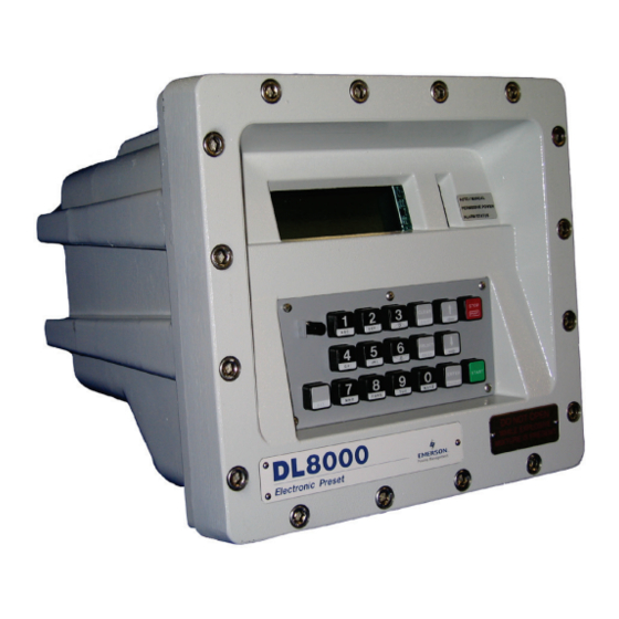
I/O modules, based on the actual devices the DL8000 monitors and controls. The DL8000 can simultaneously monitor and control operation of up to three flow meters, up to three flow control valves, and deliver up to four products. - Page 10 DL8000 Preset Instruction Manual : For specific details, refer to the technical specification DL8000 Note Preset (part D301255X012), available at www.EmersonProcess.com/Remote. Front cover bolts Display Status LEDs Weights & Measures switch Operator keypad Figure 1-2. DL8000 (in Class I, Zone 1 Enclosure) Sixteen stainless steel front cover bolts (M10 –...
-
Page 11: Electronics
(slots 1, 2, and 3) can house communication modules. The DL8000 uses a 12 volt dc Power Input module to convert 120 to 250 V ac external input power to the voltage levels required by the unit’s electronics and to monitor voltage levels to ensure proper... -
Page 12: Security Gateway
Guide (part number D301766X012). For further information, contact your Local Business Partner or the individual vendor’s website. 1.4 Additional Technical Specifications For further technical information on the DL8000, refer to the technical specification DL8000 Preset (part D301255X012), available at www.EmersonProcess.com/Remote. -
Page 13: Chapter 2 - Installation And Use
2.8.1 Keypad ..................2-24 2.8.2 LED Status Indicators ............... 2-25 This chapter describes the DL8000’s external housing, its internal electronic components (the ROC800-Series CPU), and the specifics of mechanical and electrical installation. H ousing The DL8000 uses either of two external housings: ... -
Page 14: Class I Zone 1 Housing
DL8000 Preset Instruction Manual 2.1.1 C lass I Zone 1 Housing The DL8000 Class I Zone 1 housing is cast aluminum that, when appropriately sealed, provides a flame-proof enclosure. Sixteen threaded stainless steel fasteners secure the lower portion of the housing to the hinged lid, which contains the display panel, operator keypad, and LED status display. - Page 15 DL8000 Preset Instruction Manual Figure 2-2. Standard DL8000 Enclosure : The four mounting holes on the bottom and back of the DL8000 Note case accept 10M (10mm) bolts. The DL8000’s design makes it highly adaptable to a wide variety of installations.
-
Page 16: Securing The Cover To The Class I Zone I Case
S ecuring the Cover to the Class I Zone I Case 1 0 B The DL8000 ships from the factory with the cover secured to the case with one stainless steel fastener (“bolt”). The remaining bolts are bagged and included with the DL8000. You must install all bolts. -
Page 17: Class I Div 2 Housing
DL8000 Preset Instruction Manual Figure 2-3. Bolt Tightening Sequence 2.1.3 C lass I Div 2 Housing 1 1 B The Class I, Division 2 housing includes a 14-gauge stainless steel box with 12-gauge stainless steel mounting flanges. The door is made of .090 inch thick aluminum and is secured to the box via a stainless steel... -
Page 18: Card Cage
Figure 2-4. Class I Division 2 DL8000 Housing C ard Cage The DL8000 uses electronic modules which fit into a card cage. The card cage rests inside the cast housing. See Figure 2-5 for a view of the card cage as it would appear when the housing is opened. -
Page 19: Backplane
DL8000 Preset Instruction Manual Power module Module cover Wire channel covers (removed) Figure 2-5. Card Cage (with modules) 2.2.1 B ackplane 1 2 B The backplane has connectors for the CPU, the power input module, and all the I/O and communication modules. When a module is completely inserted into the module slot, the connector on the module fits into one of the connectors on the backplane. -
Page 20: Central Processor Unit (Cpu)
DL8000 Preset Instruction Manual C entral Processor Unit (CPU) The CPU contains the microprocessor, the firmware, connectors to the backplane, three built-in communication ports (two with LEDs), a LED low power wakeup button, a RESET button, the application license key connectors, a STATUS LED indicating system integrity, and the main processor. -
Page 21: Ethernet
DL8000 Preset Instruction Manual Series 1 CPU (Green) Series 2 CPU (Black) Battery LED Button RJ-45 port License keys RESET button RJ-45 port RS-232 port Microprocessor Figure 2-7. CPU Connectors Table 2-1. CPU Connector Locations CPU Number Series 1 Series 2... -
Page 22: Installing And Removing Wire Channel Covers
Firmware update is flashing image. Do not restart the DL8000. As a power-saving feature, you can enable or disable the LEDs on the DL8000 (with the exception of the LED on the power module). You can ™ also use the ROCLINK 800 software to configure how long the LEDs remains on after the LED button on the CPU module is pressed. -
Page 23: Removing And Installing Module Covers
(see Figure 2-5) over the empty module slots in which you intend to install the modules. Although you are not required to remove the power to the DL8000 to perform this procedure, caution is always advisable when working with a powered DL8000. -
Page 24: Installing The Cpu Module
: “Critical” data may include your device configuration file, Note device alarms and events history, or displays. Remove power from the DL8000. Remove the wire channel cover. Unscrew the two captive screws on the front of the CPU module and remove the faceplate. -
Page 25: Installing A License Key
The term “license key” refers to the physical piece of hardware (see Figure 2-8 and Figure 2-9) that can contain up to seven different licenses. Each DL8000 can have none, one, or two installed license keys. If you remove a license key after enabling an application, the firmware disables the task from running. -
Page 26: Removing A License Key
: “Critical” data may include your device configuration file, Note device alarms and events history, or displays. Refer to Saving and Retrieving Configurations in the ROCLINK 800 Configuration Software User Manual (for DL8000) (part D301259X012) for further information. Remove power from the DL8000. Remove the wire channel cover. -
Page 27: Installation Planning
Installation planning consists of the following three major tasks. Assure that the DL8000 contains the required number and type of process I/O boards to monitor and control the other devices in the product delivery system. -
Page 28: Planning Considerations
The operator panel is hinged at the bottom side and opens down for maintenance access. Route all conduit to the rear, sides, or bottom of the unit. Do not locate any object under the DL8000 or in front of the conduit connections for a distance of approximately 533 mm (21 inches) below the instrument. - Page 29 19 mm (0.75 inch) from the edge. The case has a taper to the rear. The standard case may need a shim at the rear pair of screws to level the DL8000. Level the case to allow for the best conduit alignment.
-
Page 30: Electrical Installation
2 0 B Use any of three cable entries located on the bottom of the housing for wiring access to the DL8000. A threaded 25.4 mm (1-inch) female NPSM connection on the left side of the unit (for AC power and control / status signals). -
Page 31: Electrical Wire And Cable Selection And Installation
Following are recommendations for 115/230 Volts ac power wiring: Use multi-strand copper conductor wire and cable when connecting the DL8000 to the power source and the field devices. Ensure that all wire and cable is in new condition and adheres to the manufacturer's quality standards with the size, type of insulation, and voltage rating. -
Page 32: Input/Output Field Signal Wiring
The wire and cable markers should be legible and permanent. Check all wiring connected to the DL8000 for continuity, proper size, and proper classification. Verify the source or destination of each circuit before connecting to the DL8000 and related devices. - Page 33 Additionally, the ground rods must be interconnected with a continuous stranded wire, sized as indicated below. • When several DL8000 units are located in close proximity, each single-point equipment ground must be inter-connected to the single point grounds of the other DL8000s. These inter- enclosure equipment grounding connections must be “daisy-...
-
Page 34: Wire Conduit Selection And Installation
Where applicable, install explosion-proof seals in the conduit. Install drain fittings at the lowest point in the conduit run and install seals at the point of entry to the DL8000 to prevent vapor passage and accumulation of moisture. -
Page 35: Operator Interface
DL8000 Preset Instruction Manual O perator Interface : Refer to Appendix E, DL8000 Keypad Display, in this manual Note for a complete discussion of the features and functionalities of the DL8000 keypad display. The DL8000’s keypad display has the following parts:... -
Page 36: Keypad
DL8000 Preset Instruction Manual 2.8.1 K eypad 2 6 B The DL8000 keypad enables the operator to select recipes, enter the desired preset quantity, control batch deliveries, and (with appropriate authority) program the DL8000. See Figure 2-11. A: Weights & Measures Switch Figure 2-11. -
Page 37: Led Status Indicators
DL8000 is operating in Manual mode. Note: Local operation is identical in either Manual or Auto mode. Auto DL8000 is operating in Auto mode (linked to a host computer and operating as a slave unit. Flashing Two short pulses each second: case ... - Page 38 DL8000 Preset Instruction Manual This page is intentionally left blank. 2-26 Installation and Use Revised February-2016...
-
Page 39: Chapter 3 - Modules
3.1 Power Input Module The DL8000 uses a Power Input module to convert the voltage from the AC power supply to the voltage levels the DL8000 unit’s electronics require and to monitor voltage levels to ensure proper operation. All DL8000 applications use the 12 volt Power Input module. -
Page 40: Volt Dc Power Input Module
The CHG+ and CHG– terminals comprise an Analog Input channel that allows you to monitor a voltage, such as an external charging source from a solar panel. These inputs are not normally used for the DL8000. The AUX+ / AUX – terminals can be used to supply reverse-polarity- protected source voltage to external devices, such as a radio or solenoid. -
Page 41: Input/Output Modules
3.2 Input/Output Modules The I/O modules typically consist of a terminal block for field wiring and connectors to the backplane. The DL8000 supports up to nine I/O modules, and can accommodate a wide range of process inputs and outputs. Each I/O module electrically connects to field wiring by a removable terminal block. -
Page 42: I/O
I/O Slot #4 I/O Slot #7 (AC I/O module) Figure 3-3. Optional I/O Module Locations Available I/O modules for the DL8000 include: Analog Input (AI) modules that provide the ability to monitor various analog field values. Discrete Input (DI) (for DC) and Pulse Input (PI) modules that provide the ability to monitor various discrete and pulse input field values. -
Page 43: General Installation
Transducer (HART) protocol as either Analog Inputs or Analog Outputs. Each module rests in a module slot at the front of the DL8000 housing. I/O modules easily install into and remove from the module slots. You can install and remove modules while the DL8000 is powered up (hot- swappable). -
Page 44: Installing An I/O Module
DL8000 Preset Instruction Manual You can insert or remove the I/O modules while power is connected to the DL8000. If the DL8000 is powered, exercise caution while performing the following steps to install a module. : After you install a new I/O module or replace an existing I/O Note module, it may be necessary to reconfigure the DL8000. -
Page 45: Removing An I/O Module
DL8000 Preset Instruction Manual Configure the I/O point. 3.2.3 Removing an I/O Module To remove an I/O module: Remove the wire channel cover. Unscrew the two captive screws holding the module in place. Gently pull the module’s lip out and remove the module from the slot. - Page 46 For example, one module can provide +12 Volts dc for powering low-power analog transmitters, while another module in the same DL8000 controller can provide +24 Volts dc for powering conventional 4 to 20 mA transmitters. See Figure 3-5.
-
Page 47: Analog Output (Ao) Modules
The 16-bit Analog Output (AO) module has four channels that provide a current output for powering analog devices. Analog outputs are analog signals the DL8000 controller generates to regulate equipment, such as control valves or any device requiring analog control. -
Page 48: Discrete Input (Di) Modules
DL8000 Preset Instruction Manual +T 12 / 24 V dc Jumper Figure 3-7. Analog Output Jumper J4 (Shown Set to +12V) Representative Field Wiring Internal Circuit CURRENT LOOP CONTROL CURRENT LOOP DEVICE 4-20mA CURRENT LOOP ROC809 POWERED CONTROL CURRENT LOOP... - Page 49 DL8000 that the relay contacts have closed. When the contacts open, current flow interrupts, and the DI module signals the electronics in the DL8000 that the relay contacts have opened. A DL8000 can read a DI a maximum of 250 times per second.
-
Page 50: Pulse Input (Pi) Modules
+12 Volts dc or +24 Volts dc field transmitter power on a per module basis. For example, one module can provide +12 Volts dc power, while another module in the same DL8000 controller can provide +24 Volts dc power. See Figures 3-11 and 3-12. -
Page 51: Externally Powered Pulse Input Module Field Wiring
DL8000 Preset Instruction Manual +T 12 / 24 V dc Jumper Figure 3-10. Pulse Input J4 Jumper (Set to +12 V) Representative Field Wiring Internal Circuit OPEN DRAIN TYPE 12KHz PI FILTER & LEVEL DETECTION OPEN COLLECTOR DEVICE EXTERNALLY POWERED 12KHz PI FILTER &... -
Page 52: Discrete Output (Do) Modules
OPEN DRAIN TYPE DEVICE ROC800 POWERED METER COIL 2 CHAN DOC0511A Figure 3-12. DL8000 Powered Pulse Input Module Field Wiring You can induce ground loops by tying commons from various modules Caution together. 3.2.9 Discrete Output (DO) Modules The five-channel Discrete Output (DO) module provides two-state outputs to energize solid-state relays and power small electrical loads. -
Page 53: Discrete Output Relay (Dor) Modules
DL8000 Preset Instruction Manual The Discrete Output module only operates with non-powered discrete Caution devices, such as relay coils or solid-state switch inputs. Using the module with powered devices may cause improper operation or damage. The DO modules draw power for the active circuitry from the backplane. -
Page 54: Discrete Output Relay Module Field
DL8000 Preset Instruction Manual Figure 3-14 displays the field wiring connections to the output circuit of the DO Relay module. : The Discrete Output Relay module operates only with discrete Note devices having their own power source. When a request is made to change the state of a DOR, the request is immediately sent to the DOR module. -
Page 55: Resistance Temperature Detector (Rtd) Input Modules
It may be more convenient to perform calibration before connecting the field wiring. However, if the field wiring between the DL8000 and the RTD probe is long enough to add a significant resistance, then perform calibration in a manner that considers this. -
Page 56: Alternating Current Input/Output (Ac I/O) Module
DL8000 Preset Instruction Manual Signal Terminal Designation CH 2 (+) V+ RTD CH 2 (–) V– RTD CH 2 (RET) Constant Current – Not Connected You can induce ground loops by tying commons from various modules Caution together. 4-Wire RTD... - Page 57 DL8000 Preset Instruction Manual corresponding channel to output mode. Placing a switch in the OFF position sets the channel to input mode. Dual-color light-emitting diodes (LEDs) indicate the current status for each channel. Red means AC source is being output. Green means the module has detected AC on an input channel.
-
Page 58: Ac I/O
DL8000 Preset Instruction Manual : If the label on your AC I/O module does not indicate 120/240V, Note your module is designed for use only with 120V. Additionally, all AC wiring must be shielded. AC Discrete Inputs You can configure each channel as an AC input/detector. Each channel can detect the presence of an AC signal between 90 and 265 Vrms at 47 to 63 Hz. -
Page 59: Multiple Ac I/O Modules
6 channel can be configured as an input or an output. Multiple AC I/O If you need to install more than one AC I/O module in the DL8000, Modules wire the modules as shown in Figures 3-19 and 3-20. - Page 60 DL8000 Preset Instruction Manual Figure 3-19. Wiring with Multiple AC I/O Modules 3-22 Modules Revised February-2016...
-
Page 61: Advance Pulse Module (Apm)
Field wiring and DIP switch settings provide this flexibility. See Figures 3-21 through 3-30. : The DL8000 supports up to nine APMs. Note For densitometer inputs, you can designate channel 3 as a pulse input using a frequency input channel with hardware filtering for the Micro ®... -
Page 62: Generic Densitometer Wiring On
DL8000 Preset Instruction Manual EXTERNALLY POWERED DEVICE OPEN COLLECTOR OPEN DRAIN TYPE MICROMOTION ROC800 POWERED DEVICE 7835 / 7845 OPEN COLLECTOR DENSITOMETER OPEN DRAIN TYPE METER COIL Figure 3-21. Pulse Input Wiring on APM Figure 3-22. MicroMotion 7835/7845 Wiring on... -
Page 63: Independent Detector Wiring On Apm
DL8000 Preset Instruction Manual EXTERNALLY POWERED PREAMP EXTERNALLY POWERED METER PREAMP COIL 1 DET SW 1 DET SW 2 METER METER COIL 2 Figure 3-27. Independent Detector Wiring on APM Figure 3-28. Two-Pulse Turbine Pulse Input Wiring on APM NO CONNECTION... - Page 64 DL8000 Preset Instruction Manual Figure 3-30. DIP Switches on APM Table 3-6. APM DIP Switch Settings Switch Channel Side Function Switch Position Standard PI Current Modulated Densitometer Down Left 10 kΩ Pullup to 12 V dc Left No Pullup Resistor...
-
Page 65: Thermocouple (Tc) Input Module
DL8000 Preset Instruction Manual 3.2.14 Thermocouple (TC) Input Module Caution The TC2 module is NOT supported in the Series 1 CPU. The four-channel Thermocouple Input module monitors types B, C, E, J, K, N, R, S, or T thermocouples, based on how you configure the module with ROCLINK 800 Configuration software. -
Page 66: Thermocouple Input Module Wiring
DL8000. Minimize connections and make sure connections are tight. If you use any dissimilar metals (such as copper wire) to connect a thermocouple to the DL8000, you can create the junction of dissimilar metals that can generate millivolt signals and increase reading errors. - Page 67 DL8000 Preset Instruction Manual signals higher than the millivolt levels generated from a thermocouple. The TC modules can reject common mode noise (signals that are the same on both wires), but rejection is not perfect, so minimize noise where possible.
-
Page 68: Highway Addressable Remote Transducer (Hart ® ) Module
The HART-2 module (labeled HART-2 with black faceplate) replaces the HART module (with gray faceplate). The DL8000 supports up to 5 HART modules located in slots 1-5. The HART-2 module allows a DL8000 to communicate with HART devices using the HART protocol. The HART-2 module receives signals from and transmits signals to HART devices. - Page 69 DL8000 Preset Instruction Manual A DL8000 equipped with a HART-2 module is considered to be a HART Host (primary master) interface with a Class 1 Conformance classification. The HART-2 module can also be configured with ROCLINK 800 Configuration software for use as a secondary master in redundant applications.
-
Page 70: Communication Modules And Ports
Figure 3-37. Output Wiring on HART-2 Module 3.3 Communication Modules and Ports The built-in communications and the optional communication modules provide communications between the DL8000 and a host system or external devices. The DL8000 allows up to six communication ports. Three communication ports are built-in on the CPU and up to three additional ports may be added with communication modules. -
Page 71: Communication Ports
The communications modules consist of a communications module (card), a communications port, wiring terminal block, LEDs, and connectors to the backplane. The DL8000 can hold up to three communication modules in the first three module slots. See Figure 3-38. Built-in EIA-232 (RS-232) (Comm2) -
Page 72: Wiring Communications
DL8000 Preset Instruction Manual Table 3-8. Communication LED Indicator Definitions Signals Action Clear To Send indicates the modem is ready to send. Data Carrier Detect (DCD) indicates a valid carrier signal tone detected. Data Set Ready for ring indicator communication signal. -
Page 73: Local Operator Interface (Loi - Local Port)
The LOI port supports ROC Plus and Modbus protocol communications. The LOI also supports the log-on security feature of the DL8000 if you enable the Security on LOI feature in ROCLINK 800 software. Table 3-9 shows the signal routing of the CPU connections. Figure 3-39 shows the RJ-45 pin out. -
Page 74: Using The Loi
Order CBL8A from your Remote Automation Solutions salesperson. 3.3.3 Using the LOI Plug the LOI cable into the LOI connector on the DL8000 CPU. Connect the LOI cable to the D-Sub 9 pin (F) to RJ-45 modular converter. - Page 75 DL8000 Preset Instruction Manual MAC mechanism is based on Carrier Sense Multiple Access with Collision Detection (CSMA/CD). If two stations begin to transmit a packet at the same instant, the stations stop transmitting (Collision Detection). Transmission is rescheduled at a random time interval to avoid the collision.
-
Page 76: Rs-232) Serial Communications
DL8000 Preset Instruction Manual about noise. If you suspect noise related data errors, it may be necessary to either reroute the cable or eliminate the source of the impulse noise. Multi-pair, PVC 24 AWG telephone cables have an attenuation of approximately 8 to 10 dB/100 m at 200°C (392°F). -
Page 77: Eia-422/485 (Rs-422/485) Serial Communications Module
DL8000. The EIA-232 (RS-232) communication provides essential hand-shaking lines required for radio communications, such as DTR and RTS. -
Page 78: Eia-422/485 (Rs-422/485) Jumpers And Termination Resistors
DL8000 Preset Instruction Manual The default values for the EIA-422/485 (RS-422/485) communications are: 19200 Baud rate, 8 data bits, 1 stop bit, and no parity. The maximum rate is 57.6K bps. EIA-422/485 (RS-422/485) communication modules include LED indicators that display the status of receive and transmit activity. See Tables 3-14 and 3-15. -
Page 79: Dial-Up Modem Communications Module
DL8000 Preset Instruction Manual Figure 3-41. EIA-422/485 (RS-422/485) J4 Jumper Table 3-16. EIA-422 (RS-422) Module Terminated Not Terminated Jumper Half Full Half Full Table 3-17. EIA-485 (RS-485) Module Terminated Not Terminated Jumper Half Full Half Full 3.3.8 Dial-up Modem Communications Module The dial-up modem module interfaces to a Public-Switched Telephone Network (PSTN) line. - Page 80 DL8000 Preset Instruction Manual : When installing a dial-up modem module, you must remove Note power from the DL8000. The dial-up modem provides communications with speeds up to 14.4K bps with V.42 bis and V.42, MNP2-4 and MNP10 error correction.
-
Page 81: Additional Technical Information
DL8000 Preset Instruction Manual Additional Technical Information Refer to the following technical documentation (available at www.EmersonProcess.com/Remote) for additional and most-current information on each of the modules. Table 3-20. I/O Module Technical Specifications Name Form Number Part Number ROC800-Series Analog Input Modules... - Page 82 DL8000 Preset Instruction Manual [This page is intentionally left blank.] 3-44 Modules Revised February-2016...
-
Page 83: Appendix A - Glossary
DL8000 Preset. American Gas Association. A professional organization that oversees the AGA3 (orifice), AGA5 (heating value), AGA7 (turbine), AGA8 (compressibility), and AGA11 (ultrasonic) gas flow calculation standards. - Page 84 Blending The process of mixing two or more liquid components to form a composite delivered stream. The DL8000 controls blending based on a predetermined recipe by either the sequential (automatic or manual) or the inline (proportional or non-proportional) method. The quantity of each component in a blend is typically greater than two to four percent of the blended product.
- Page 85 DL8000 Preset Instruction Manual Decibel. A unit for expressing the ratio of the magnitudes of two electric signals on a logarithmic scale. Data Carrier Detect modem communications signal. In addition, Discrete Control Device – A discrete control device energizes a set of discrete outputs for a given setpoint and matches the desired result against a set of discrete inputs (DI).
- Page 86 Integral Multiplier Value, used in AGA3 (orifice) calculations. Indicated The change in the flow meter reading that occurs during a product flow measurement Quantity operation. (Not displayed by the DL8000 calculation: indicated quantity = end reading minus start reading.) Input Digital input, a bit to be read.
- Page 87 DL8000 Preset Instruction Manual Input Register Input numeric value to be read. Input/Output. I/O Module Module that plugs into an I/O slot on a ROC to provide an I/O channel. IP-252 Institute of Petroleum standard 252. A British standard for pulse fidelity and security for pulse output type flow meters.
- Page 88 The K-factor is used to derive a mathematical factor, known as meter factor, which is used to adjust results of the internal flow calculations the DL8000 performs. Note: The flow meter is not re-calibrated; determining the meter factor allows the operator to manually re-calibrate the DL8000 so that the flow meter’s...
- Page 89 Personal Computer. Permissive A discrete signal from a device that is input to a discrete input in the DL8000. The DL8000 uses this signal to allow a product delivery to be initiated or allow a product delivery to continue. Permissive contacts are CLOSED in the normal or safe state and OPEN in the abnormal or unsafe state.
- Page 90 Recipe A pre-entered delivery/blending/control description that allows the DL8000 to automatically control the product quantity or total quantity based on percentages of multiple components during a batch delivery operation. The DL8000 supports up to thirty recipes. Radio Frequency Interference. Ring Indicator modem communications signal.
- Page 91 DL8000 Preset Instruction Manual SAMA Scientific Apparatus Maker’s Association. Script An uncompiled text file (such as keystrokes for a macro) that a program interprets in order to perform certain functions. Typically, the end user can easily create or edit scripts to customize the software.
- Page 92 DL8000 Preset Instruction Manual Volts. Volume The actual space occupied by the product measured, indicated in one of the following actual units: cubic meters, liters, barrels, gallons. Wild Stream Wild stream is the uncontrolled stream, often referring to the gasoline product. This is because the gasoline product cannot be exclusively metered, controlled, or measured.
-
Page 93: Appendix B - Modbus Communications
FST Registers, user programs, and DS800 programs. The DL8000 can also send commands to set outputs and write data to a slave device. For more information on Modbus master configuration and functionality, refer to Section A.6, Modbus Master Table. -
Page 94: Modbus Configuration
DL8000 Preset Instruction Manual Modbus Configuration From the ROCLINK 800 menu bar, select Configure > MODBUS. The Modbus Configuration screen displays, showing the General tab (see Figure B-1). Use the individual tabs to: General Defines basic communication parameters Scale Values... -
Page 95: Modbus Configuration General Tab
DL8000 Preset Instruction Manual B.2.1 Modbus Configuration General Tab Complete the following steps to configure the Modbus Configuration screen’s General tab. Review the values in the following fields: Field Description Comm Port Indicates the port to configure. Click to display additional available ports. - Page 96 Requests sequence. Timeout Indicates, in seconds, the actual amount of time the DL8000 waits to receive a value message after it sends a request to the device. Note: Do not enter zero (0) in this field. Retries Controls the number of times (in addition to the...
-
Page 97: Modbus Configuration Scale Values Tab
DL8000 Preset Instruction Manual Click Apply to save any changes you have made to this screen. Proceed to Section B.2.2 to define scale values. B.2.2 Modbus Configuration Scale Values Tab Select the Scale Values tab to enter up to eight low and high floating point scale values and one low and high integer values for converting floating point numbers to a scaled integer. - Page 98 DL8000 Preset Instruction Manual only on analog I/O specified by the I/O: AI raw A/D input (Type 3, Parameter 17) and AO raw D/A output (Type 4, Parameter 17). Float In host systems that do not accept floating point numbers, you can specific up to eight sets of floating point ranges.
-
Page 99: Modbus History
1980. For example, if the current year is 2007, the year (YY) for the date stamp would be 07. The DL8000 maps history collection on the Modbus History Table. -
Page 100: Modbus Configuration History Table Tab
Daily history values and Event/Alarm records for retrieval through Modbus Protocol, using Function Code 03. You define three registers to retrieve the current date in the DL8000, the current time in the DL8000, and Event/Alarm records. You can also use the Modbus History Table to define the Periodic and Daily registers for up to twenty groups of history points. - Page 101 Events/Alarms log (default 32). The Current Date and Current Time values identify the current date and time on the DL8000 and are most useful if you want the date and time as floating point numbers in the format DDMMYY and HHMM.
- Page 102 Group Identifies a contiguous group of history points from a single segment whose values the DL8000 can access through a Modbus Function Code 03 request for a user-defined Modbus register. You can define up to 20 groups.
-
Page 103: Modbus Events & Alarms Functionality
When the DL8000 receives a Function Code 03 request referencing defined Events/Alarms Register (usually 32), the DL8000 begins to collect records from first the Event Log and then the Alarm Log, starting where the last poll left off. The DL8000 then collects records until either there are no more new events/alarms or the maximum of twelve records have been collected. -
Page 104: Modbus Registers
DL8000 Preset Instruction Manual Table B-4. Modbus Events and Alarms Log Contents Byte Contents of Event Log Record Contents of Alarm Log Record Operator change (Event Log) bit map (16-bit Alarm change bit map (16-bit integer). See Table integer). See Table B-5. - Page 105 TLP’s data type is appropriate for the function code. Notes If the native DL8000 data type does not meet the requirements of the Modbus host device, conversion codes are available to convert the data to the required data type. Contact technical support personnel.
-
Page 106: Modbus Configuration Registers Tab
DL8000 Preset Instruction Manual B.5.1 Modbus Configuration Registers Tab To access this screen: Select Configure > MODBUS. The Modbus Configuration screen displays. Select the Registers tab. The Modbus Registers screen displays. Figure B-4: Modbus Configuration – Registers Tab Review the values in the following fields:... - Page 107 Note: Certain Modbus host devices transmit the register 40101 as 100. In those cases, place 100 in this field, since the DL8000 uses the actual host-send value. For example, a host device requests start register 500 through end register 700.
- Page 108 Conversion Indicates the type of data conversion (if any) required before the data is either sent to the host or written to the DL8000. Conversions accommodate differences in data types between slave and master devices. See Table B-6. Note: Conversion codes affect Function Codes 3, 4, 6, 8, and 16.
-
Page 109: Modbus Conversion
Modbus History screens) to specify the type of conversion required, if any, on the data before it is sent to the host or before it is written to the DL8000. The conversions are used to account for differences in data types between the master and slave devices. -
Page 110: Modbus
Description Definition Code Function conversion changes a transmitted floating point Any type to Unsigned Short 3,4,6,16 value to the correct data type for the DL8000 TLP. Integer Any type to Unsigned Long 3,4,6,16 Integer 30 to 32 No Conversion No Conversion... -
Page 111: Modbus Master Table
Each master request you configure must have a corresponding entry in the Modbus Registers table. When using Modbus Function Codes 1 to 4, the DL8000 reads data from a slave device and writes it to the TLP specified in the Modbus Registers table. When using Modbus Function Codes 5, 6, 15, and 16, the DL8000 reads data from the TLP specified in the Modbus Registers table and writes it to the slave device. -
Page 112: Modbus Configuration Master Table Tab
DL8000 Preset Instruction Manual slaves. The DL8000 will retry three times to establish a connection with a slave. You can create an FST to schedule Modbus Master requests. The FST must set the Start Polling checkbox on the Modbus Configuration screen’s General tab (Configure >... - Page 113 Indicates the starting Modbus register number for the query on this slave device. Master Register Indicates the starting Modbus register number where the queried data is stored on the master DL8000 device. Number of Indicates the total number of registers in the range.
-
Page 114: Modbus Master Modem
Modbus slave RTU addresses to their respective phone numbers. Up to six different Modbus slaves can be dialed through one communication port. The DL8000 retries three times to establish a connection with a slave. B.7.1 Modbus Configuration Master Modem Tab To access this screen: Select Configure >... - Page 115 Indicates the telephone number (connect command) Command to be sent to the slave device. Click Apply to save any changes you have made to this screen. This completes the process of configuring the DL8000 for Modbus communications. Revised February-2016 Modbus Communications...
-
Page 116: Hmi Information
DL8000 Preset Instruction Manual HMI Information This section provides two tables that indicate how the DL8000 monitors batching status via Modbus. B.8.1 Sequential Blending Table B-8 lists the monitoring codes for sequential blending in manual mode. Table B-8. Sequential Blending Status Codes... -
Page 117: Ratio Blending
DL8000 Preset Instruction Manual Status Status Name Request for Aux 4 Data Archive Transaction B.8.2 Ratio Blending Table B-9 lists the monitoring codes for ratio blending in manual mode. Table B-9. Ratio Blending Status Codes Status Status Name Select Recipe... - Page 118 DL8000 Preset Instruction Manual This page is intentionally left blank. B-26 Modbus Communications Revised February-2016...
-
Page 119: Appendix C - Wiring Diagrams
DL8000 Preset Instruction Manual Appendix C – Wiring Diagrams This appendix presents wiring examples for several standard Emerson devices. For other devices, refer to the manufacturer’s specifications. Daniel Senior Sonic Meter to PI Module DANIEL SENIOR SONIC METER 12KHz PI FILTER &... -
Page 120: Daniel 1818A And 1838 Turbine Pre-Amp To Pi Module
DL8000 Preset Instruction Manual Daniel 1818A and 1838 Turbine Pre-Amp to PI Module DANIEL PREAMP TURBINE 1818A PICKUP METER COIL 15-28 VDC 12KHz PI FILTER & LEVEL DETECTION SQR. WAVE COMMON 12KHz PI FILTER & TURBINE LEVEL DETECTION PICKUP METER... -
Page 121: Micro Motion Rft9739 & 2400S Transmitters To Pi Module
DL8000 Preset Instruction Manual Micro Motion RFT9739 & 2400S Transmitters to PI Module MICRO MOTION RFT9739 TRANSMITTER 12KHz PI FILTER & LEVEL DETECTION 12KHz PI FILTER & LEVEL DETECTION MICRO MOTION RFT9739 TRANSMITTER DOC0740A MICRO MOTION 2400S TRANSMITTER 12KHz PI FILTER &... -
Page 122: Micro Motion Rft9739 & 2400S Transmitters To Apm Module
DL8000 Preset Instruction Manual Micro Motion RFT9739 & 2400S Transmitters to APM Module MICRO MOTION RFT9739 TRANSMITTER MICRO MOTION RFT9739 TRANSMITTER MICRO MOTION 2400S TRANSMITTER MICRO MOTION 2400S TRANSMITTER Wiring Diagrams Revised February-2016... -
Page 123: 3- And 4-Wire Rtd To Rtd Module
DL8000 Preset Instruction Manual 3- and 4-Wire RTD to RTD Module 4 - WIRE RTD 3 - WIRE RTD Revised February-2016 Wiring Diagrams... -
Page 124: Daniel Senior Sonic Meter To Apm Module
DL8000 Preset Instruction Manual Daniel Senior Sonic Meter to APM Module DANIEL SENIOR SONIC METER DANIEL SENIOR SONIC METER Wiring Diagrams Revised February-2016... -
Page 125: Daniel 1818A And 1838 Dual Turbine Pre-Amp To Apm Module
DL8000 Preset Instruction Manual Daniel 1818A and 1838 Dual Turbine Pre-Amp to APM Module DANIEL PREAMP TURBINE 1818A PICKUP METER COIL 15-28 VDC SQR. WAVE COMMON TURBINE PICKUP METER COIL 15-28 VDC SQR. WAVE COMMON DANIEL PREAMP 1818A TURBINE PICKUP... -
Page 126: Daniel 1818A And 1838 Turbine Pre-Amp To Apm Module
DL8000 Preset Instruction Manual Daniel 1818A and 1838 Turbine Pre-Amp to APM Module DANIEL PREAMP TURBINE 1818A PICKUP METER COIL 15-28 VDC SQR. WAVE COMMON PICKUP 15-28 VDC COIL SQR. WAVE COMMON DANIEL PREAMP 1818A TURBINE PICKUP DANIEL PREAMP METER... -
Page 127: Two-Stage Valve With Two Limit Switches To Apm Module
DL8000 Preset Instruction Manual Two-Stage Valve with Two Limit Switches to APM Module PERMISSIVE POWER AC L1 PERMISSIVE NEUTRAL UPSTR N.O. MICRO SWITCH DNSTR N.C. MICRO SWITCH UPSTREAM SOLENOID N.O. DOWNSTREAM SOLENOID N.C. Revised February-2016 Wiring Diagrams... -
Page 128: Micro Motion 1700 & 2700 Transmitter To Pi Module
DL8000 Preset Instruction Manual C.10 Micro Motion 1700 & 2700 Transmitter to PI Module MICRO MOTION 1700 & 2700 TRANSMITTER L1 120 Vac 12KHz PI FILTER & LEVEL DETECTION NEUTRAL 12KHz PI FILTER & LEVEL DETECTION DOC0848A C-10 Wiring Diagrams... -
Page 129: Appendix D - Communications Protocols
[X,Y,Z] where X is the point type number, Y is the logical number, and Z is the parameter number. For that reason we also cite pertinent DL8000 parameters in the format [X,Y,Z] and, when necessary, include specific code values. -
Page 130: Communication Channels
If you have configured a comm port for either Modbus or DanLoad 6000 protocol and the TAS is in automatic mode, the system scans for communications failures. It raises an alarm when the DL8000 does not receive a valid request on the specified comm port within the configured time. -
Page 131: Supported Protocols
The TAS can communicate with a DL8000 using either the Modbus protocol or the DanLoad 6000 protocol. Modbus You can configure a DL8000 to use either Modbus RTU or ASCII Protocol transmission modes, and either Most Significant Byte (MSB) or Least Significant Byte (LSB) orders. - Page 132 BCC with the received BCC. Any differences indicate a data error; the destination does not reply to such command frames. The DL8000 knows which function code to expect from the TAS. If it receives hex 41h when it expects hex 42h or vice versa (and the...
-
Page 133: Configuration
Manual (Part Number 3-9000-674, Revision 2.1, publication date September 1998) for details on the DanLoad 6000 protocol and command request or query frame. D.1.4 Configuration To set up a serial port in the DL8000, use the following configurations: Value Description Device Address Sets the DL8000’s address [91,0,0]. -
Page 134: Commands
If the system finds no exceptions during the processing of commands, it sets and resets any required status flags [63,0,119] and controls the DL8000 based on the command. Refer to Section D.9 and D.10 for a list of exception codes the Modbus or DanLoad 6000 protocols might raise. -
Page 135: Status Flags
D.1.6 Status Flags The Status Flags parameter [63,0,119] maintains various process values which the TAS uses to monitor the status of both the DL8000 and the overall batching operation. : These values accumulate in the TLP and do not currently appear Note on any system report or screen. -
Page 136: Batch Control In Auto Mode
TAS. D.2.1 Steps for Authorizing a Transaction The DL8000 allows you to load a preset volume of a product, blend, or recipe as a “batch.” The operator or the TAS sets the (preset) volume. - Page 137 Before a transaction can begin an operator must select a recipe. The TAS can use the Prompt Recipe (hex 0x01) command and request the DL8000 to prompt the operator for a recipe selection. The DL8000 then displays a recipe selection screen on which the recipe names display beginning with the first recipe up to the maximum number of configured recipes [63,0,26].
- Page 138 TLP. When the operator enters data from the keypad, DL8000 sets a flag (bit 7 in [63,0,119]) to indicate when keypad data is available. Based on the auxiliary data item number, the system writes data entered from the keypad as Data Item 1 [63,0,188], Data Item 2 [63,0,190], Data Item 3 [63,0,192], Data Item 4 [63,0,194] and Data Item 5 [63,0,196].
-
Page 139: Steps For Authorizing A Batch
Preset Volume for Batch The TAS can command the DL8000 to prompt the operator for a preset volume using the Prompt Preset Volume command (hex 0x08). When the TAS issues this command, the DL8000 displays a preset selection screen. -
Page 140: Stop/End Of Batch
[63,0,171]. If the batch is aborted (that is, if the operator presses Stop instead of Start or the DL8000 times out waiting for the Start key to be pressed), the DL8000 sets the batch aborted and timeout flags (bits 14 and 3), resets the batch authorized flag (bit 17 in [63,0,119]), and reduces the batch sequence number [63,0,125] by 1. -
Page 141: End Of Transaction
Current Alarm Type [63,0,64] has a value more than 1). A batch that is stopped because of these conditions may be restarted. The DL8000 sets a flag (bit 21 in [63,0,119]) to indicate that the batch has stopped and can be restarted. -
Page 142: Batching Status States
D.2.5 Batching Status States The Batching Status parameter [63,0,9] maintains various process values which the TAS uses to monitor the status of both the DL8000 and the overall batching operation. : These values accumulate in the TLP and do not currently appear Note on any system report or screen. -
Page 143: Communications Commands
Table D-1 lists the executable commands available in the Modbus protocol. These commands are called “executables” since they force the DL8000 to perform certain kind of activities. The table also specifies the operation mode in which each command is valid. -
Page 144: Prompt Recipe (0X01)
Reading status flags and totalizers Reading alarm status Prompt Recipe Allows the TAS to let an operator select a recipe at the DL8000. The command locks out the keypad and display (K&D) to the TAS. [0x01] The DL8000 displays a recipe selection screen to operator on which the recipe names displayed starting from first recipe up to the number of recipes [63,0,26] configured. -
Page 145: Prompt Additives (0X03)
This command does not result in an additive selection being set in the DL8000. It just allows the TAS to obtain a possible additive selection from an operator at the DL8000. The TAS can change the additive selection by writing its own value at [63,0,60] (using Modbus write function code), but only when the transaction is not authorized and the Operation Timed Out flag is not set. -
Page 146: Timeout Operation (0X05)
DL8000 Preset Instruction Manual Timeout Operation If this command is issued when the DL8000 is prompting for a recipe, for additives, for a preset volume, for keypad input, displaying a message, or [0x05] waiting for the operator to start or abort a batch, then the current operation times out. - Page 147 set) Additive user program is not running in DL8000 Additives module is running in DL8000 and suggested additive method [63,0,170] is not either 0 or 1. Returns Invalid additive selection method exception. Suggested additive method [63,0,170] is 0 and ...
- Page 148 If an operator presses Stop while a transaction is in progress and the batch is not in progress or the batch is stopped, then the DL8000 sets the Transaction End Requested flag (bit 19 in [63,0,119]) to indicate the request for a transaction end.
-
Page 149: Authorize Batch (0X0A
Modbus read function code. Authorize Batch Authorizes the batch for given preset volume [63,0,39]. When the batch authorizes, the DL8000 displays a loading screen. This also increments the [0x0A] batch sequence number [63,0,125] by 1 (which may roll from 9999 to 0) to indicate the prospective sequence number if the batch starts. - Page 150 [63,0,171]. If the batch aborts (that is, the operator presses Stop instead of Start or the DL8000 times out waiting for the Start key to be pressed), the DL8000 sets the Batch Aborted and Operation...
- Page 151 Use this command to “remote control” a DL8000 when an operator cannot be in the proximity of the DL8000. In these circumstances the TAS can entirely control the DL8000, which may not even be fitted with a display or keypad. Flags Immediately Set...
-
Page 152: Stop Batch (0X0F)
If Stop key action is Immediate (1), then batch is stopped immediately and no pump stop delay used. The DL8000 sets a flag to indicate that the batch has stopped (and is restartable). Flags Immediately Set Batch Stopped (if batch gets stopped) ... - Page 153 Program Mode (0x16 bit) When the DL8000 is in program mode, it can reset only the Program Mode flag; otherwise an exception occurs. Note: If any of the flags requested to be reset are not allowed to be reset, then no flag resets out of those requested to be reset.
- Page 154 [0x1C] If auxiliary data index [63,0,178] is non-zero and is less than or equal to the number of data items [63,0,186], then the DL8000 displays a prompt to the operator (using appropriate data prompt message [63,0,187;189;191;193;195]) to enter/request the appropriate data item before authorizing a new transaction.
- Page 155 [63,0,178]. Set Date and Time Sets the date and time (if transaction is not authorized in the DL8000) written in TA Set Time (63,0,174) to battery-backed real-time clock. [0x29] The date and time is written as a 4-byte integer and represents the number of seconds elapsed since January 1, 1970, at 12AM.
- Page 156 Results As above Change Operating Allows the TAS to change the DL8000’s operating mode as written in the TAS’s operating mode [63,0,180] with options (0=Auto, 1=Manual). If the Mode DL8000 is already in the desired mode, the command is just acknowledged.
- Page 157 Raising an alarm based on conditions that are either not input to or not detectable by the DL8000 (such as a fire detection system or a PLC being used to monitor a rail car’s position). Stopping a batch with a situation-specific message. In this case, the TAS ...
-
Page 158: Danload 6000 Protocol Commands
D.3.2 DanLoad 6000 Protocol Commands The following table lists the DanLoad 6000 protocol commands, indicates which DanLoad 6000 protocol commands the DL8000 supports, designates the operating mode (automatic or manual) in which the command is valid, and notes which commands which are purely read or write. - Page 159 DL8000 Preset Instruction Manual Cmd No Cmd No Command Name Valid modes Command Type (decimal) (hex) (Automatic/Manual) supported Transaction data by Read component Initialize Transaction Storage Start Communication Request program code Read values and attributes Set program code value Write...
-
Page 160: Exception Codes
September 1998) for a definitive discussion of commands and request and response frames for the DanLoad 6000 protocol. Prompt Recipe Enables an operator to select a recipe at the DL8000. The TAS is locked out of the keypad and display. [0x01]... - Page 161 This command does not result in an additive selection being set in the DL8000. It just enables the TAS to obtain a possible additive selection from an operator at the DL8000. The TAS can set the additive selection using the Authorize Transaction command.
- Page 162 in Progress. Request Enables the TAS to request—once the DL8000 sets the additive flag (bit 5 in [63,0,119]) to indicate that the operator has selected additives—the selected Selected Additives additive using this command. The TAS specifies an additive selection in the [0x04] Authorize Transaction command.
-
Page 163: Authorize Transaction (0X06
Transaction operator selection and provide a new recipe, additive, or data items as part of [0x06] this command. DL8000 displays the “Transaction Auth” and “Please Wait” messages. Note: The TAS can read user-entered data items using the Display Message command (0x1C). - Page 164 DL8000 and suggested additive method received is 0 and forced additive bitmap received is non-zero. Additives module is running in DL8000 and suggested additive selection method received is not 0 or 1. Returns Invalid additive selection method exception.
-
Page 165: Prompt Preset Volume (0X08)
DL8000 displays “Trans Ended” and “Please wait” messages until it receives the next command. If an operator presses Stop when transaction is in progress and the batch is not in progress, then the DL8000 sets the Transaction End Requested flag (bit 19 in [63,0,119]). Flags Immediately Set... - Page 166 Volume Entered flag. The TAS uses the Request Preset Volume command to Preset Volume request that preset volume, as well as further validate the operator-entered [0x09] preset volume, and sets the volume in the DL8000 using the Authorize Batch [0x0A] command. Flags Immediately Set None...
- Page 167 Start within the timeout time [63,0,171]. If the batch aborts (that is, the operator presses Stop instead of Start or the DL8000 times out waiting for the Start key to be pressed), the DL8000 sets the Batch Aborted and Operation Timed Out flags (bits 14 and 3) and resets the Batch Authorized flag (bit 17 in [63,0,119]).
- Page 168 [72,x,8]. The units of gravity or density should be same as those configured in the DL8000 at parameter Density Units Option [70,0,3]. If there is an online input to the TAS, update the backup densities or gravities using the Authorize Batch [0x0A] command.
- Page 169 Use this command to “remote control” a DL8000 when an operator cannot be in the proximity of the DL8000. In these circumstances the TAS can entirely control the DL8000, which may not even be fitted with a display or keypad. Flags Immediately Set...
-
Page 170: Start/Restart Batch (0X0E)
If Stop key action is Immediate (1), then the batch stops immediately without using a pump stop delay. The DL8000 sets a flag to indicate that the batch has stopped (and is restartable). Flags Immediately Set Batch Stopped (if batch gets stopped) ... - Page 171 DL8000 Preset Instruction Manual Batch Data Once a batch ends, the DL8000 sets a flag to indicate that the batch has ended and cannot be restarted. The TAS system can then use this command by Component to request the data for the batch.
-
Page 172: Additive Totalizer (0X11
Deviations None Request Status Displays the overall status of the DL8000. For the command response, see the Results section. [0x12] Status flags is a binary representation of the DL8000’s 32 status flags. Safety circuit status is the current logical state (“open” or “closed”) of 8 general purpose safety circuit inputs. - Page 173 [63,0,111] – returned alarm code is in terms of DanLoad 6000. Value stored at this parameter is alarm code used by DL8000 which may not match with alarm code of DanLoad 6000. Alarm bitmaps of ten bytes (returned in terms ...
- Page 174 [0x14] This enables the TAS operator to automatically reset the primary alarm “remotely” without requiring a DL8000 operator logging into program mode. The system raises an Unable exception if it is unable to reset the alarm (that is, a configuration-corrupted alarm cannot be reset if count of corrupt configuration parameters [63,0,2] is more than 0.)
-
Page 175: Meter Totalizers (0X15)
DL8000 Preset Instruction Manual Reset Deviations Some DL8000 alarms may not map directly to DanLoad 6000 alarms. Primary Alarms [0x14] Additional exceptions are supported such as invalid alarm ID and Unable to reset the alarm. DL8000 allows reset of non-primary alarms;... -
Page 176: Unauthorized Flow (0X17)
(Use the Reset Primary Alarms command to reset an unauthorized flow alarm or reset the alarm at the DL8000 itself.) Flags Immediately Set None... - Page 177 Max average over 1 sec flow rate Number of pulses received at different flow rate set points Pulse count is a 4-byte value in DL8000 and a 2-byte value in DanLoad 6000. For this reason, value may not be accurate beyond 65535.
- Page 178 [69,x,13;14;15;16;17] Actual component % in batch [69,x,59] Deviations None Request Power Fail Reads date and time at which DL8000 last lost its power. This value stores in the system parameters [91,0,47]. Date and Time [0x1B] Flags Immediately Set None...
- Page 179 If the timeout time received in the command request frame is less than 0, then the DL8000 uses the configured timeout time [63,0,171]. If timeout is set as zero then a timeout never occurs (that is, a message or prompt displays until the DL8000 receives a Timeout Operation command [0x05]).
- Page 180 Request Retrieves input requested via Display Message command [0x1C]. When keypad input is terminated, the DL8000 sets a flag to indicate that the keypad Keypad Data data is available. [0x1D] Flags Immediately Set...
- Page 181 % 10000 where % is the C language modulus operator. On warm up booting, the DL8000 calculates the current transaction and batch record lengths. If the current transaction record length does not equal the stored transaction record length [61,0,120], the system raises a transaction configuration error [61,0,133].
-
Page 182: Transaction Data By Component (0X1F)
Transaction Data by Requests data for the transaction after the current transaction has ended. The DL8000 sets a flag indicating that the transaction has ended. In manual Component operating mode, press Stop to end a transaction when there is a transaction [0x1F] in progress and no batch in progress. - Page 183 Preset Additive option [64,0,26] is additional feature not available in DanLoad 6000 protocol (applicable for Version 2.0 and later). Swing arm side is not supported in DL8000, so its value returned in the command response frame is always 1 (applicable only for Version Initialize Transaction Clears all stored transaction history records and initializes them at zero.
-
Page 184: Initialize Transaction Storage (0X20)
Communication failure alarm reset. The TAS can start or initiate communication with the DL8000 using this command. If communications are already started when this command is received, then the communication link is re-initialized but operations at the DL8000 are unaffected. The command resets the alternating function code sequence, using function codes 41h or 42h for the query. - Page 185 Request Program Code A program code value is a number. A program code identifies a variable (parameter) in DanLoad 6000. This parameter is mapped to DL8000. A Values and Attributes program code value is the value of variable identified by the program code [0x22] and can be a number of byte length depending on the program code.
-
Page 186: Set Program Code Value (0X23)
The other flags are not supported. Set Program Use this to configure the DL8000 from a TAS. The DL8000 validates the program code value being sent and responds with exception code 45h if it is Code Value not valid. - Page 187 (flag=1) for different recipes on the same DL8000. This is a function of the size of meter (and thus the usable range of flow rates) through which the component flows. You may need to modify the overall recipe low and high flow rates [68,x,23 and 24] if you modify component percentages through communications.
-
Page 188: Get Date And Time (0X28)
Set Date and Time Validates the date and time received in the command request frame the TAS issues. If both the date and time are valid, the DL8000 sets its battery-backed [0x29] real-time clock in point type 136 (ROC Clock). -
Page 189: Last Key Pressed (0X31)
The DL8000 has only one CPU, and responds with the version number of the user programs. Reset Unit Initiates a warm restart of the DL8000 (similar to a power-up), and restarts all user program. This command cannot be issued when a transaction is in [0x30] progress. - Page 190 For Version 2.0: In auto mode, if alarm raises then mode changes to manual and current batch completed before ending the transaction. If transaction is authorized and this command is issued then the DL8000 ends the current transaction. The operating mode changes after the current transaction ends.
- Page 191 Use this command to request the transaction record from the (transaction storage) transaction file. You can configure the format of the transaction Transaction record and the DL8000 only archives the configured parameters. Valid [0x39] transaction sequence numbers are 0 through 9999.
- Page 192 Each history data is returned as consecutive 4-bytes data. All the parameters of double data type in DL8000 will be returned as 4- bytes unsigned long and all others will be returned as 4-bytes float data.
- Page 193 Request Stored Use this command to request the batch record from the (transaction storage) batch file. You can configure the format of the batch record; the DL8000 Batch archives only the configured parameters. Valid batch sequence numbers are [0x3A] 0 through 9999.
- Page 194 DL8000 Preset Instruction Manual The command response frame differs from that of the DanLoad 6000 protocol: struct Tasr Unsigned char dfl // datafield length Unsigned char cmdcode; // command code Unsigned long transactionSeqNum; // transaction sequence no. for this batch Unsigned long configMode;...
- Page 195 Each history data is returned as consecutive 4-bytes data. All the parameters of double data type in DL8000 are returned as 4-bytes unsigned long and all others will be returned as 4-bytes float data.
- Page 196 Communication failure alarm reset. the TAS can start or initiate communication with the DL8000 using this command. If communications are already started when this command is received, then the communication link is re-initialized but operations at the DL8000 are unaffected. The command resets the alternating function code sequence, using function codes 41h or 42h for the query.
- Page 197 Language used [63,0,14] Deviations The Temperature correction option [71,x,28] values the DL8000 returns do not directly map to the DanLoad 6000 program codes 432, 435, etc. for all values. The Pressure correction option [71,x,29] values the DL8000 returns do not directly map to the DanLoad 6000 program codes 444, 447, etc.
- Page 198 DL8000 Preset Instruction Manual Enhanced Request Status This command can be issued at any time to know the overall status of DL8000 unit. This command is an alternative to Request Status command [0x12]. [0x3C] This command has the following advantages over the Request Status [0x12]...
- Page 199 [63,0,111] – returned alarm code is in terms of DanLoad 6000. Value stored at this parameter is alarm code used by DL8000 which may not match with alarm code of DanLoad 6000. Alarm bitmaps of ten bytes (returned in terms ...
- Page 200 Raising an alarm based on conditions that are either not input to or detectable by DL8000 (such as a fire detection system or a PLC being used to monitor a rail car’s position). Stopping a batch with a situation-specific message. In this case, the ...
-
Page 201: Mapping Modbus Registers
ROCLINK 800 provides Modbus register tables you use to map Modbus registers to TLP (Point Type, Logical, and Parameter) numbers in the DL8000. To access these tables, select Configure > Modbus > Registers from the ROCKLINK 800 menu bar. The Modbus Registers screen displays. - Page 202 : If the native data type does not meet the requirements of the Note Modbus Host device, conversion codes are available to convert the data to the required data type. For the DL8000, you can select to have the mapping apply to all communication ports or on a selected port only.
- Page 203 DL8000 Preset Instruction Manual table for Modbus Function 3, 4, or 16 up to the limit of 240 bytes. This type of data table allows access to all its data with one request. Periodic (Hourly) or Daily History Index registers should be mapped to the TLP for the Periodic Index (Point Type 124, Parameter 5) or Daily Index (Point Type 124, Parameter 6).
-
Page 204: Danload 6000 Protocol Frame
DL8000 Preset Instruction Manual DanLoad 6000 Protocol Frame The DanLoad 6000 protocol supports a maximum of 256 bytes in one Request/Response frame. Numeric data is transmitted in binary with LSB byte first and MSB byte last. Frame queries, responses, and exception responses using the following... -
Page 205: Bcc Calculation
DL8000 Preset Instruction Manual BCC Calculation The destination station uses block check characters (BCCs) to verify the accuracy of received data. The transmitting station calculates the BCC for each message and transmits them. The receiving station then calculates the BCC for each message it receives and then compares the calculated BCCs to the received BCCs. -
Page 206: Checksum Table
DL8000 Preset Instruction Manual CRC-16 Checksum Table Use the following database to calculate CRC-16 values for the DanLoad 6000 protocol frame. Table D-3. CRC-16 Checksum Const unsigned short crc16Table[256] = 0x0000, 0xc1c0, 0x81c1, 0x4001, 0x01c3, 0xc003, 0x8002, 0x41c2, 0x01c6, 0xc006, 0x8007, 0x41c7, 0x0005, 0xc1c5, 0x81c4, 0x4004,... - Page 207 DL8000 Preset Instruction Manual 0x0182, 0xc042, 0x8043, 0x4183, 0x0041, 0xc181, 0x8180, 0x4040}; Revised February-2016 Communications Protocols D-79...
-
Page 208: Status Flags Description [63,0,119
TAS issues End Batch command for authorized batch which is not in progress (in auto mode). DL8000 powers up for a previously authorized batch which was not in progress when DL8000 powered down. Note: If authorized batch was running, flag resets. - Page 209 0Dh bit (in auto mode). Batch halts (due to alarm or operator pressing Stop) and cannot be restarted. Operating mode changes. DL8000 powers on; batch was in progress when DL8000 powered down. Batch in Progress Batch starts/restarts. Batch ends (sets 0Dh).
- Page 210 TAS, keypad, auto to manual by TAS or or digital input. keypad. Operation Timed Out DL8000 is waiting for recipe Prompt Recipe, Prompt selection, additive selection, Additive, Prompt Preset preset volume entry, for start of...
- Page 211 DL8000 Preset Instruction Manual Status Flag Flag sets when… Flag resets when… does not change. mode). Prompt Recipe command received. Recipe selection screen is prompted (in manual mode). Operating mode changes. DL8000 powers up. Clear Status command received ...
- Page 212 DL8000 Preset Instruction Manual Status Flag Flag sets when… Flag resets when… Transaction Authorized Transaction authorizes (in DL8000 powers up. manual mode) Transaction ends or aborts. Authorize Transaction Operating mode changes and command received (in auto transaction authorizes.
-
Page 213: Exception Codes
Exception Codes In automatic mode, the TAS sends various commands to control the DL8000. Each command code can be accepted or rejected based on the DL8000 status. If the command is rejected, then the DL8000 generates an exception and writes the exception code to the TAS exception code [63,0,168]. - Page 214 DL8000 Preset Instruction Manual Exception # (hex value) Description Operating mode is manual No preset volume entered No recipe selected No additive selection made Data items not entered No key pressed Diagnostic not running. Transaction not on file Batch not on file...
-
Page 215: New/Unused Danload 6000 Exception Codes
D.10 New/Unused DanLoad 6000 Exception Codes The following exception codes have been added to the DanLoad 6000 protocol to support the DL8000. These codes are not present in the original DanLoad 6000 protocol. Table D-6. New/Unused DanLoad 6000 Exception Codes... -
Page 216: Alarm Logs
DL8000 Preset Instruction Manual D.11 Alarm Logs The DL8000 uses the following alarms. Table D-7. Alarm Logs Alarm Name Alarm ID Name in Event Log Unable to maintain blend Blend Fail X Configuration corrupted Config corrupt Parameter restored Param restored Over flow preset quantity O.F. - Page 217 DL8000 Preset Instruction Manual Group Alarm Name Alarm ID Name in Event Log Flow rate too high – meter X 105 + High Flow X meter no Timed-out no flow detected – 115 + No Flow X meter X meter no...
-
Page 218: Error Codes
DL8000 Preset Instruction Manual D.12 Error Codes Following are error codes for the DL8000 protocol. Table D-8. Error Codes Error Code [63,0,95] Reasons No Error Invalid recipe number Incorrect delivery sequence or low proportion Incorrect component ratios. This exception is raised if either of the following conditions is not satisfied. -
Page 219: Appendix E - Dl8000 Keypad Display
The keypad display uses port 2 (RS-232 on the CPU module) to Warning communicate with the DL8000. The required baud rate for this port is 57.6K. Changing these values or assigning any other functionality to port 2 (such as the DanLoad 6000 or Modbus protocol) causes a communication failure to the keypad display. -
Page 220: E.1.1 Keypad
E.1.1 Keypad Using the keypad, you can select recipes, enter the desired preset quantity, control batch deliveries, and—with appropriate authority— program the DL8000. See Figure E-2. A. Weights & Measures Switch Figure E-2. DL8000 Keypad : The Weights & Measures switch, located in the left upper corner... - Page 221 DL8000 Preset Instruction Manual : The program validates what you can enter in any field. If a field Note accepts only numeric values, pressing ALT+1 generates only the decimal. If the field accepts both alphabetic and numeric values, pressing ALT+1 displays A, B, C, and the decimal.
-
Page 222: Led Status Indicators
Function YELLOW Manual DL8000 is operating in Manual mode. Auto DL8000 is operating in Auto mode (linked to a host computer and operating as a slave unit). Two short pulses each second: case Flashing internal temperature is too high. -
Page 223: Liquid Crystal Display (Lcd
Weights & Measures switch. E.1.4 Power Failure If power fails to the keypad display (but not to the DL8000 itself) for more than 5 seconds or if communications fail to the keypad display for more than 5 seconds, the system generates the Keypad Display Communications Failure (K &... -
Page 224: Operational Modes
The following screens show the screen sequences during normal batch setup and delivery operations. : Since you can easily change the content of the DL8000 displays, Note the screen in this section are only examples and may not correspond exactly to the appearance of the displays on your DL8000s. -
Page 225: Invalid Recipe Selection
14/02/12 13:58:59 Invalid Recipe (Press CLEAR) (Info message) E.2.3 Additive Selection If the system has at least one additive, the DL8000 displays the Additive Selection screen. The operator can then select the required additives. 14/02/12 13:58:59 Recipe #1... -
Page 226: Preset Quantity
DL8000 Preset Instruction Manual : If you defined multiple data items, the DL8000 displays a Note data item screen for each data item defined. 14/02/12 13:58:59 Recipe #1 Enter data item #n (ENTER to Continue) E.2.5 Preset Quantity The operator uses this screen to enter the preset quantity. - Page 227 DL8000 Preset Instruction Manual Table E-3 lists the possible status messages that could display on the Loading screen during various stages during the load: Table E-3. Loading Screen Status Messages Message Description Start to Load Press Start key to start loading...
-
Page 228: Transaction End Prompt
If the operator selects at least one end transaction prompt, this screen displays during the transaction end sequence (n indicates the end transaction prompt). : If you defined multiple transaction prompts, the DL8000 Note displays all defined end transaction prompts in sequence. - Page 229 DL8000 Preset Instruction Manual Table E-4. Net Totalizers TLP No. Meter Parameter 75,X,7 Meter Net Std Volume (Unathorized) 75,X,12 Meter Net Std Volume (Batch) 75,X,17 Meter Net Std Volume (Authorized) 75,X,35 Transaction Start Net Std Reading 75,X,38 Transaction End Net Std Reading...
-
Page 230: Program Mode
Note Weights & Measures icon. E.3.1 ROCLINK 800 Configuration You must set DL8000 security to enable an operator ID to access program mode. Alternately, you may use one of the two personal identification numbers (PINs) ROCLINK 800 provides to permit administrative access to the keypad display program. -
Page 231: Log In
DL8000 Preset Instruction Manual The Navigation Setup screen displays. Select the PINs tab to display the PINs screen: A. Default administrative PINs Figure E-5. PINs Screen PIN 1 has a factory default of 8000; PIN 2 is blank. Define four-digit codes appropriate to your organization. -
Page 232: Initial Menu
DL8000 Preset Instruction Manual 14/02/12 13:58:59 Enter PIN E.3.3 Initial Menu When you press Enter, the system display the Program main menu. The right-hand screen shows menu options. 14/02/12 13:58:59 Clear Alarms Select Language Choose an Option Print Record... -
Page 233: E.3.5 Select Language
<– (Press for Menu) E.3.5 Select Language This screen displays when you select Select Language on the Program Mode screen. Use it to adjust the language displayed for the DL8000 prompts. 14/02/12 13:58:59 Current language: ENGLISH (SELECT to change <–... -
Page 234: E.3.7 Display Setting
DL8000 Preset Instruction Manual E.3.7 Display Setting This screen displays when you select Display Setting on the Program Mode screen. Use it to adjust the backlighting and contrast on the display. 14/02/12 13:58:59 Display Setting Contrast Adjust Backlight Adjust <–... - Page 235 DL8000 Preset Instruction Manual Press ENTER to continue. The program displays the Current Status menu: 14/02/12 13:58:59 System General Stream Batch Additive Transaction Meter Recipe Alarm (Pg:1/1) The keypad display program does not display all the TLPs in the preset.
-
Page 236: Alarm
DL8000 Preset Instruction Manual SYSTEM Menu Transaction Headings (Submenu Page 1) (1 logical, point types 63 & 64) Trans Number 63,0,124 Trans Gross Del 63,0,140 Trans Mass Del 63,0,143 Trans Srt Dt Tm 63,0,230 Trans End Dt Tm 63,0,231 Trans Net Std Del... - Page 237 DL8000 Preset Instruction Manual STREAM Menu Headings (Submenu Page 3) Low CompTemp 69,X,44 High CompTemp 69,X,46 Low CompPress 69,X,48 High CompPress 69,X,50 Low CompDens 69,X,52 High CompDens 69,X,54 Headings (Submenu Page 4) Low TempTimestamp 69,X,45 High TempTimestamp 69,X,47 Low PressTimestamp...
- Page 238 DL8000 Preset Instruction Manual METER Menu Running Totals Headings (Submenu Page 1) (4 logicals, point type 75) Meter Mass 75,X,18 Meter GrsVol 75,X,15 Meter Net Vol 75,X,17 UnauthMtr Mass 75,X,8 UnauthMtr GrsVol 75,X,5 UnauthMtr Net Vol 75,X,7 Alarm Headings (Submenu Page 1)
-
Page 239: Apm
DL8000 Preset Instruction Manual String on Menu Submenu Submenu Submenu Parameter Display Screen API Level Liquid Turbine Pulse sec. Status Auditor Check 1 APM level 62,0,187 Turb1 Liquid Turbine Pulse sec. 2 APM level 62,0,188 Turb2 Liquid Turbine Pulse sec. -
Page 240: E.3.9 Setup/ Configuration
DL8000 Preset Instruction Manual String on Menu Submenu Submenu Submenu Parameter Display Screen Component Component Status Auditor Details Comp. Name 69,x,6 Meter Factor/K- M-Fact/K- Factor Option 69,x,74 Fact Optn Meter Factor 69,x,9 M-Fact K-Factor 69,x,8 K-Fact Master Meter Master M-... - Page 241 DL8000 Preset Instruction Manual 14/02/12 13:58:59 For traversing use System | DOWN Component LEFT | RIGHT Meter ENTER To Continue Valve EXIT To Go Back Recipe EXIT To Quit Additive (Pg:1/3) 14/02/12 13:58:59 For traversing use History | DOWN...
- Page 242 DL8000 Preset Instruction Manual An option may have additional options or may immediately display modifiable parameters: 14/02/12 13:58:59 PRESET:1/1 Language English Unit Type Seg. Auto Valve Type Std Digital Date Format DD/MM/YY Operating Mode Manual Preset Del Type Gross vol...
- Page 243 DL8000 Preset Instruction Manual (TLP) Parameter accepts a TLP value [0,0,0]. To define a TLP, press SELECT. The system displays valid IO module values. Press ENTER to define a module. (If you select a module which is not installed the message Req. Card not in Sys displays). The system prompts you to choose a logical.
- Page 244 DL8000 Preset Instruction Manual Table E-7. Menus & Submenus in Setup/Configuration Menu Sub-menu Sub-menu System General Flush Inline Config Prompt Driver Verificn End O/P Alarm Flow Alarm Process Alarm System Alarm Safety Alarm I/O Alarm Component General Delivery Meter Fac.Curve...
- Page 245 DL8000 Preset Instruction Manual Menu Sub-menu Sub-menu ROC Settings General Keypad Display Display Properties Generic TLP entry Direct TLP Access COM port Settings COM Parameters BaudRate Generator PortOwn. & Timeout PID Settings PID Settings Online Help Help Menu Help Parameter Table E-8 shows the parameters and associated TLPs under each sub menu.
- Page 246 DL8000 Preset Instruction Manual SYSTEM Menu Headings (Submenu Page 3) Min. Preset 63,0,27 Max. Preset 63,0,28 Max Trans Limit 63,0,4 Batches/Trans 63,0,126 Display Qty Type 63,0,30 Gross vol Net Std vol Mass Legal Record 63,0,39 No record Printout History Headings (Submenu Page 4)
- Page 247 DL8000 Preset Instruction Manual SYSTEM Menu Prompt Headings (Submenu Page 1) (1 logical, point type 63) No of End prom 63,0,228 Data prompt 1 63,0,187 Data prompt 2 63,0,189 Data prompt 3 63,0,191 Data prompt 4 63,0,193 Data prompt 5...
- Page 248 DL8000 Preset Instruction Manual SYSTEM Menu Lock Unit RampDownAlmAct 63,0,35 Display Stop Batch Close Contact Lock Unit UnderFlowAlmAct 63,0,42 Display Stop Batch Close Contact Lock Unit Headings (Submenu Page 2) Low Flow Time 63,0,38 High Flow Time 63,0,40 No Flow Time...
- Page 249 DL8000 Preset Instruction Manual SYSTEM Menu Alarm, Process Alarm Headings (Submenu Page 1) (1 logical, point type 63) Min Comp Temp 63,0,157 Max Comp Temp 63,0,158 Min Comp Dens 63,0,163 Max Comp Dens 63,0,164 Min Comp Press 63,0,160 Max Comp Press...
- Page 250 DL8000 Preset Instruction Manual SYSTEM Menu Calc Bound Alm Act 64,0,13 Display Stop Batch Close Contact Lock Unit Alarm, Safety Alarm Headings (Submenu Page 1) (1 logical, point types 63 & 64) Circuit1 Alm Act 63,0,65 Display Stop Batch Close Contact...
- Page 251 DL8000 Preset Instruction Manual SYSTEM Menu Circuit 4 Type 64,0,13 Side indepn If ldng at S1 If idng at S2 Headings (Submenu Page 3) Circuit 5 Type 63,0,81 Side indepn If ldng at S1 If idng at S2 Circuit 6 Type...
- Page 252 DL8000 Preset Instruction Manual COMPONENT Menu Low Flw Strt Qty 69,X,0 Low Flw Stop Qty 69,X,2 Low Flw Rstrt Qty 69,X,1 LP High Flow Rate 69,X,57 Headings (Submenu Page 2) Stop Flow Rate 69,X,56 Meter Fac. Curve Headings (Submenu Page 1)
- Page 253 DL8000 Preset Instruction Manual METER Menu General Headings (Submenu Page 1) (4 logicals, point type 75) Meter ID 75,X,1 Mtr Flow Direction 75,X,52 Normal flow Revs flow Rev Meter Vlv Sov1 75,X,85 Rev Meter Vlv Sov2 75,X,86 Sov1 Ret time...
- Page 254 DL8000 Preset Instruction Manual METER Menu Temp Probe 2 TLP 75,X,32 VALVE Menu Digital Vlv. Cntrl Headings (Submenu Page 1) (1 logical, point type 63) Recovery Retries 63,0,22 Recovery Delay(s) 63,0,31 Fallback Delay(s) 63,0,23 Digital Vlv. Band Headings (Submenu Page 1)
- Page 255 DL8000 Preset Instruction Manual RECIPE Menu Adtv 10 cntrlComp 68,X,52 Recipe Additives 68,X,53 Adtv. Injection Mtd, Adtv. Headings (Submenu Page 1) Multirate Add 1 Ratio Qty 68,X,7 (30 logicals, point type 68) Add 2 Ratio Qty 68,X,8 Add 3 Ratio Qty...
- Page 256 DL8000 Preset Instruction Manual ADDITIVE Menu AddSelectionMthd 63,0,102 Inch3 Gallons (US) Liters Barrels Prompt Preset Add Option 64,0,26 Discrete I/P Recp Sel Recp Mlti Rt Add PumpStopDelay 63,0,106 Exclusive Inclusive Delivery Headings (Submenu Page 1) (10 logicals, point type 67)
- Page 257 DL8000 Preset Instruction Manual HISTORY Menu Headings (Submenu Page 2) Clear History Opt 61,0,124 Choose An Option Clr Num of Records Release & Acquire Batch Hist Config Headings (Submenu Page 1) (1 logical, point type 61 & 65) Pressure (FWA)
- Page 258 DL8000 Preset Instruction Manual HISTORY Menu Component MF 61,0,206 Disabled Enabled Component CTL 61,0,215 Disabled Enabled Component CPL 61,0,216 Disabled Enabled Headings (Submenu Page 5) NetForward Mass 65,0,12 Disabled Enabled Reverse Meter Mass 65,0,14 Disabled Enabled Meter Mass Batch 65,0,19...
- Page 259 DL8000 Preset Instruction Manual HISTORY Menu Adtv Gross Qty 61,0,39 Disabled Enabled Headings (Submenu Page 4) Swing Arm Side 61,0,231 Disabled Enabled Trans Hist Errors Headings (Submenu Page 1) (1 logical, point type 61) Trans. Cfg Error 61,0,133 Read only...
- Page 260 DL8000 Preset Instruction Manual UNIT Menu Flow Rate Option 70,0,8 Per Minute Per Hour Per Second Per Day LIQUID SETUP Menu Liquid Preference Headings (Submenu Page 1) (1 logical, point type 70) Press Unit Option 70,0,1 Kg/cm2 Temp Units Option...
- Page 261 DL8000 Preset Instruction Manual LIQUID SETUP Menu Liquid Product Headings (Submenu Page 1) (5 logicals, point type 72) Fluid Type 72,X,1 Gasoline Jet fuel Fuel oil Lube oil Special Appn Light Hydrocarbon Ethanol Crude oil PetroMeas TableOpt 72,X,2 Table_2004_API Table_1980_API...
- Page 262 DL8000 Preset Instruction Manual COM PORT SETTINGS Menu BaudRate Generator Headings (Submenu Page 1) (1 logical, point type 91) BaudRate Gen 0 91,0,31 BaudRate Gen 1 91,0,32 BaudRate Gen 2 91,0,33 BaudRate Gen 3 91,0,34 Port Own. & Timeout Headings (Submenu Page 1)
-
Page 263: Clear Alarms
DL8000 Preset Instruction Manual PID SETTINGS Menu Output High Limit 110,X,42 E.3.10 Generic TLP for Setup and Status The keypad display program cannot display all the TLPs available in the preset. However, the program does provide a general TLP entry function you can use to access a TLP not usually available. - Page 264 DL8000 Preset Instruction Manual 14/03/12 12:26:02 Enter Type Enter Logical Enter Parameter ENTER to Continue UP | DOWN EXIT to Quit (0-9) Press to access each value. Once you define the TLP, press Enter to save your changes. The program validates the TLP you have entered.
-
Page 265: E.3.11 Online Help
DL8000 Preset Instruction Manual 14/03/12 12:26:02 TLP Entered Current value Param Attribute Read Write Cndl Pls Open WM Switch ENTER to Continue And Try again EXIT to Go Back Press ATL+CLEAR to exit and return to the TLP entry screen. You can either enter a new value or open the W&M switch and press ENTER to... - Page 266 DL8000 Preset Instruction Manual Select Help Menu to display this screen: 14/03/12 12:26:02 Right arrow Jump to Next page Left arrow Jump to Prev page Up arrow Jump to Next line Down arrow Jump to Prev line EXIT To go back...
-
Page 267: E.4 Calibration
During calibration, the DL8000 times-out and reconnects if left idle for Caution an extended period. In this case, you lose all calibration values and must reconnect to the DL8000 and restart the calibration. No error or warning message occurs. Each calibration process has its own menu. Select Calibration in program mode. -
Page 268: Calibrating Additive Meters
DL8000 Preset Instruction Manual 14/03/12 12:26:02 WM Switch is Closed Pls open the Switch And try again You must open the W&M switch in order to perform calibrations. E.4.1 Calibrating Additive Meters Select Additive Calib to start the additive calibration process. - Page 269 DL8000 Preset Instruction Manual Error Message Description Adtv not config The parameter maximum additives parameter [63,0,100] is set to 0 At the beginning of the calibration, the program checks for the “No additive configured” and “Additive user program not running”...
- Page 270 DL8000 Preset Instruction Manual 14/03/12 12:26:02 Enter Prover Qty. ENTER to continue) (0-9, .) Once you provide a prover volume and press ENTER, the system displays a meter factor: 14/03/12 12:26:02 Current MF 1.000000 Corrected Qty 0.000000 Additive Units New MF 0.000000...
-
Page 271: Calibrating Analog Input
DL8000 Preset Instruction Manual 14/03/12 12:26:02 For traversing use Additive Calib | DOWN Analog Calib LEFT | RIGHT RTD Calib ENTER to continue PRODUCT Calib EXIT to Go Back EXIT to quit (Pg:1/1) E.4.2 Calibrating Analog Input : The preset must have an installed AI module to calibrate AI. If... - Page 272 DL8000 Preset Instruction Manual Press ENTER to continue the calibration process and display the next screen, which shows the live value from the analog source: 14/03/12 12:26:02 Live Dead Enter ZERO EU -0.09100 Enter SPAN EU (ENTER to update (STOP to End (0-9, .)
-
Page 273: Calibrating Rtds
DL8000 Preset Instruction Manual Once the calibration completes, the program displays a summary screen. You can then accept or reject the new calibration value(s): 14/03/12 12:26:02 Live Dead Enter ZERO EU -0.09100 Enter SPAN EU 99.857282 (ENTER to accept... - Page 274 DL8000 Preset Instruction Manual 14/03/12 12:26:02 For traversing use Additive Calib | DOWN Analog Calib LEFT | RIGHT RTD Calib ENTER to continue PRODUCT Calib EXIT to Go Back EXIT to quit (Pg:1/1) The preset displays all available RTD channels. In sequence, you select...
-
Page 275: Rtd
DL8000 Preset Instruction Manual After you provide all the parameters required for calibration press ENTER to continue. The program then displays the live value from an external source with a corresponding “dead” (expected) value you can change. 14/03/12 12:26:02... - Page 276 DL8000 Preset Instruction Manual The program performs the following range checks: Set Zero: Entered value ≥ Minimum Range AND Entered value ≤ Maximum Range Set Span: Entered value > Set Zero AND Entered value ≤ Maximum Range Set Mid-points (1, 2, 3): Entered value ≥ Set Zero AND Entered value ≤...
-
Page 277: Calibrating Product Meters
E.4.4 Calibrating Product Meters Unlike the DanLoad 6000 (which required manual calibration of product meters), the DL8000 performs most of the calibration steps automatically. When appropriate, the program prompts you for required data. You can enter this information from the keypad display. - Page 278 DL8000 Preset Instruction Manual TLP [69,X,9] TLP [69,X, 78] TLP [69,X, 76] Flow Profile Figure E-6. Multiple Flow Rates with a Single Meter Factor Each flow rate in the system has a separate MF. For example, if the Multiple MF...
- Page 279 DL8000 Preset Instruction Manual : Whether you select single and multiple meter factors changes the Note process of product calibration slightly. Differences, as appropriate, are noted. Select PRODUCT Calib to start the product meter calibration process. 14/03/12 12:26:02 For traversing use...
- Page 280 DL8000 Preset Instruction Manual You can either press EXIT to quit product calibration or STOP to end the current transaction. If a transaction is in progress and you press STOP, the transaction ends and batching status moves to 1 (Select Recipe).
- Page 281 DL8000 Preset Instruction Manual 14/03/12 12:26:02 Select Component Component 1 ENTER to Continue Exit to Go Back (SELECT) Press SELECT to choose a component and then press ENTER to move to the next screen in the process. (Press EXIT to redisplay the Delivery Type selection screen.)
- Page 282 DL8000 Preset Instruction Manual component-related option using either the Setup/Configuration option on the keypad display or ROCLINK 800. If you are satisfied with the displayed meter factor/K-factor option, press ENTER to continue. The system then displays the current value for the meter factor: ...
- Page 283 DL8000 Preset Instruction Manual 14/03/12 12:26:02 Flowrate 1 0.000000 Flowrate 2 0.000000 Flowrate 3 0.000000 Flowrate 4 0.000000 | DOWN ENTER to Continue The system can display a maximum of four flow rates on one page. If you have defined more than four flow rates, they appear on the next and subsequent pages (for a maximum of three pages).
- Page 284 DL8000 Preset Instruction Manual Select Flow Point Values When calibrating with multiple meter factors, it is essential that you (Multiple MFs) proceed in steps, first calibrating product at a low flow rate and then proceeding to progressively higher flow rates. Calibrating the product at low flow rates ensures that inaccuracies at lower flow rates do not get added when calibrating at a higher flow rate.
- Page 285 DL8000 Preset Instruction Manual If the system finds any problems, displays an error message: 14/03/12 12:26:02 EXIT To Go Back Flowrate Cfg Error To resolve any configuration errors, press EXIT to return to the previous screen and re-define the flow rates.
- Page 286 DL8000 Preset Instruction Manual Disables Auto select recipe [64,0,5] (This occurs as soon as you select the Product Calibration option) Switching from After you complete the configuration, the preset automatically switches Program Mode to from program mode to loading mode. In loading mode, the preset...
- Page 287 DL8000 Preset Instruction Manual 14/02/12 13:58:59 Recipe #1 Loaded: Corrected: 60 deg F Temp: Vol Units: Gal Gross: Net: (Status Message) (Status Message) If the batch stops (“halts”) during loading due either to user intervention or an alarm halt, one of the following screens displays: ...
- Page 288 DL8000 Preset Instruction Manual Condition to check SL. No. valid batch Action taken volume. System displays a screen with updated information on Batch loaded Qty and Current MF and prompts you to enter a prover volume. User halt or alarm...
- Page 289 DL8000 Preset Instruction Manual If you enter a prover volume of zero, the system retains the old meter factor. Single MF/K-factor When you press ENTER, the system updates the meter factor parameter Option [69,X,9] with the new value and displays a screen allowing you to rerun the batch.
- Page 290 DL8000 Preset Instruction Manual Press EXIT to rerun the batch. The system displays the Rerun option screen, displaying rerun options (based on the selected MF/K-factor option). : The system does not generate an alarm for a fallback condition. Note (This is a feature of the preset.) Instead, the system monitors for...
- Page 291 DL8000 Preset Instruction Manual Multiple MF/K-factor If you are using the multiple MF/K-factors option, this screen provides Option the following options: 14/03/12 12:26:02 Rerun Batch Calib new FR SP Calib new Prod EXIT To Quit Select Rerun Batch. The system redisplays the loading screen: ...
- Page 292 DL8000 Preset Instruction Manual 14/03/12 12:26:02 Additve Calib Can Prover Analog Calib RTD Calib PRODUCT Calib (Pg:1/1) Press EXIT again to display the Calibration menu screen: 14/03/12 12:26:02 For traversing use Additive Calib | DOWN Analog Calib LEFT | RIGHT...
-
Page 293: Diagnostics
(Pg:2/2) : When diagnosing IO modules, you can either use an external Note signal source or use DL8000 modules (for example, for DI diagnostics, you can use a DO module to generate signals). E.5.1 Diagnosing Digital Outputs (DO) : The preset must have an installed DO module to diagnose the Note DO. - Page 294 DL8000 Preset Instruction Manual Figure E-8. DO Module Field Wiring Select DO to perform DO diagnostics: 14/03/12 12:26:02 For traversing use | DOWN LEFT | RIGHT ENTER to continue EXIT to Go Back ACIO EXIT to quit RS232 (Pg:1/2) The system displays a channel selection screen.
- Page 295 DL8000 Preset Instruction Manual Press SELECT to specify a DO channel number for testing: 14/03/12 12:26:02 Test DO Ch DO ch 1 Use DI Ch (SELECT) Press SELECT to specify a DI channel number which is connected to the test DO: ...
-
Page 296: Diagnosing Digital Inputs (Di
DL8000 Preset Instruction Manual 14/03/12 12:26:02 Test DO Ch DO ch 1 Use DI Ch NONE DO Current Status(SEL to toggle Sts (STOP to End Press SELECT to toggle the status of the DO channel. The DI status updates accordingly. - Page 297 DL8000 Preset Instruction Manual Figure E-9. DI Module Field Wiring Select DI to perform DI diagnostics: 14/03/12 12:26:02 For traversing use | DOWN LEFT | RIGHT ENTER to continue EXIT to Go Back ACIO EXIT to quit RS232 (Pg:1/2) The system displays a channel selection screen.
- Page 298 DL8000 Preset Instruction Manual 14/03/12 12:26:02 Test DI Ch DI ch 1 Use DO Ch DO ch 1 (SELECT) : For an external source, select None. Note 14/03/12 12:26:02 Test DI Ch DI ch 1 Use DO Ch...
-
Page 299: Diagnosing Analog Outputs (Ao
DL8000 Preset Instruction Manual If you used an external resource for the DO (the Use DO Ch option is None), the DI channel status updates according to the external contact. The system displays the following screen: 14/03/12 12:26:02 Test DI Ch... - Page 300 DL8000 Preset Instruction Manual Figure E-10. AO Module Field Wiring Select AO to perform AO diagnostics: 14/03/12 12:26:02 For traversing use | DOWN LEFT | RIGHT ENTER to continue EXIT to Go Back ACIO EXIT to quit RS232 (Pg:1/2) The system displays a channel selection screen.
- Page 301 DL8000 Preset Instruction Manual 14/03/12 12:26:02 Test AO Ch AO ch 1 Use AI Ch AI ch 1 (SELECT) : For an external source, select NONE. Note 14/03/12 12:26:02 Test AO Ch AO ch 1 Use AI Ch...
- Page 302 DL8000 Preset Instruction Manual 14/03/12 12:26:02 Test AO Ch AO ch 1 Use AI Ch AI ch 1 AO current val(EU) 10.000000 AI current val(EU) 9.911288 Set AO current val STOP to End : If you are using an external resource for analog input, the system...
-
Page 303: Diagnosing Analog Inputs (Ai
DL8000 Preset Instruction Manual Once the diagnosis is in process, the program checks only for the following AI alarms: Point fail alarm. (Terminate diagnostics) Scanning manual alarm (Info alarm) If multiple alarms occur, the system displays the alarm with the highest priority. - Page 304 DL8000 Preset Instruction Manual A. 250 Ohm precision resistor Figure E-11. AI Modules Field Wiring : Connect a 250 Ω precision resistor (as shown) for the AI-12 Note module if the AI channel carries a 4–20 mA signal. The AI-16 module has an onboard 250 Ω...
- Page 305 DL8000 Preset Instruction Manual 14/03/12 12:26:02 Test AI Ch AI ch 1 Use AO Ch AO ch 1 (SELECT) : For an external source, select NONE. Note 14/03/12 12:26:02 Test AI Ch AI ch 1 Use AO Ch...
- Page 306 DL8000 Preset Instruction Manual 14/03/12 12:26:02 Test AI Ch AI ch 1 Use AO Ch AO ch 1 AI current val(EU) 99.969406 AO current val(EU) Set AO current val STOP to End : If you are using an external resource for analog input, the system...
-
Page 307: Diagnosing Ac Input/Outputs (Ac I/O
DL8000 Preset Instruction Manual 14/03/12 12:26:02 Point Fail Alarm EXIT To Go Back Additionally, the system does not show any alarms for the AI module once diagnostics tests are in progress. : If you connect the AI with an external contact instead of an AO Note channel, the current AI value updates with the external contact. - Page 308 DL8000 Preset Instruction Manual Figure E-12. AC I/O Module Output Field Wiring Figure E-13. AC I/O Module Input Field Wiring Select ACIO to perform AC I/O diagnostics: 14/03/12 12:26:02 For traversing use | DOWN LEFT | RIGHT ENTER to continue...
- Page 309 DL8000 Preset Instruction Manual 14/03/12 12:26:02 Test AC Output Ch AC ch 7 Use AC Input Ch AC ch 1 (SELECT) Specify the ACIO channel for testing. You can test only the AC ouput, only the AC input, or both AC output and input.
- Page 310 DL8000 Preset Instruction Manual If you define an internal AC I/O module for both AC input and AC output, after you select the required channels press ENTER to start the diagnostics: 14/03/12 12:26:02 Use AC Output Ch Ac ch 7...
-
Page 311: Diagnosing Rs-232 Communication Ports
DL8000 Preset Instruction Manual 14/03/12 12:26:02 Use AC Output Ch NONE Use AC Input Ch NONEAC I/p curr Sts (SEL to toggle Sts) (STOP to End If you set Use AC Output ch to NONE and select an available AC input channel, the program interprets this to mean you have connected an external AC output to the selected input. - Page 312 DL8000 Preset Instruction Manual Select RS232 to test RS-232 communications: 14/03/12 12:26:02 For traversing use | DOWN LEFT | RIGHT ENTER to continue EXIT to Go Back ACIO EXIT to quit RS232 (Pg:1/2) The system displays a comm. port selection screen.
-
Page 313: Diagnosing Rs-485 Communication Ports
DL8000 Preset Instruction Manual After the transmission portion of the test completes, the system tests all baud rates, from lowest to highest. (Baud rates checked include 300, 600, 1200, 2400, 4800, 9600, 19200, 38400, and 57600). As the test of each baud rate completes successfully, the system adds a P (for passed) to the display. - Page 314 DL8000 Preset Instruction Manual Figure E-14. Jumpers on RS-485 Module Table E-9. Jumper Settings on RS-485 Module for Half-duplex Unterminated Mode Terminated Not Terminated Jumper Half Full Half Full Hardware/ Connect the two RS-485 modules to perform external loopback Wiring...
-
Page 315: Rs-485) Module
DL8000 Preset Instruction Manual (RS 485 Module 1) (RS 485 Module 2) Figure E-15. Two RS-485 Modules with Loopback Connection Table E-10. RS-485 Module Signals Signal RS-485 Function Terminal RX / TX + Lit when module (Comm3, Comm4, or Comm5) is currently receiving. - Page 316 DL8000 Preset Instruction Manual 14/03/12 12:26:02 Sel Main Ch RS485 ch 4 ENTER to Continue (SELECT) EXIT to Quit Press ENTER to continue (or press EXIT to redisplay the main Configuration menu). The system prompts you to select a test channel.
- Page 317 DL8000 Preset Instruction Manual Once you have at least two RS-485 modules installed and both are un- assigned to any application and you have defined both a main and a test channel, the following screen displays: 14/03/12 12:26:02 Set Port...
-
Page 318: Error Messages
Press STOP to end the test and return to the comm port selection screen. Press EXIT to display the Diagnostics main menu. E.5.8 Error Messages Table E-11 lists error messages that could appear on the DL8000 display. Table E-11. Error Messages... -
Page 319: Translated Alarm And Status Messages
Side not authorized Selected swing arm side not authorized E.5.9 Translated Alarm and Status Messages Table E-12 lists translated alarm and status messages that could appear on the DL8000 keypad display. Table E-12. Translated Alarm and Status Messages English Spanish... - Page 320 DL8000 Preset Instruction Manual English Spanish Portuguese No Flow Sin Flujo Sem Vazao Pres Fail Falla Pres. Falha Pressao NaN Found NaN encontrado Valor N recon Data Error Found Error de Datos Falha de Dados BV Fail BV Falla Falha Valv Bloq...
-
Page 321: Setup/Configuration
DL8000 Preset Instruction Manual English Spanish Portuguese Invd Primary Comp Comp.Primari Inval Comp Prim Invalido Flowrate Too High Flujo muy alto Vazao muito Alta Flowrate Too Low Flujo muy bajo Vazao muito Baixa Trans Limit Cross Lim. Trans Excedid Lim Trans Excedido... - Page 322 DL8000 Preset Instruction Manual English Spanish Portuguese Select from the \r\n Seleccionar Receta de Following Recipes entre las \r\n siguientes Selecione uma das Receitas Invd Recipe Receta inválida… Receita Invalida Press SELECT \r\n to Pulse SELECT \r\n p/ Choose elegir...
-
Page 323: Index
DL8000 Preset Instruction Manual Index DanLoad 6000 ..........D-46 Modbus ............D-25 Numbers Codes 3- & 4-Wire RTD ..........C-5 Error .............. D-90 Exception, DanLoad 6000 ......D-87 Cold Junction Compensation (CJC) ....3-27 Communication channels ........D-2 AC Discrete Inputs ..........3-20 Communication failures ........ - Page 324 3-32. Ungrounded - Sheathed ...... 3-29 1-1. Typical DL8000 Load Rack ..... 1-2 3-33. Grounded ..........3-29 1-2. DL8000 (in Class I, Zone 1 Enclosure) ... 1-4 3-34. Exposed, Ungrounded – Unsheathed . 3-29 2-1. Standard DL8000 Enclosure ....2-2 3-35.
- Page 325 DL8000 Preset Instruction Manual E-14. Jumpers on RS-485 Module ....E-96 Modbus Protocol ..........D-1 E-15. Two RS-485 Modules with Loopback Modbus Registers Connection ..........E-97 Mapping ............D-73 Modules .............. 3-1 AC I/O ............3-18 AI-12 ............... 3-7 Get Date and Time (0x28) AI-16 ...............
- Page 326 DL8000 Preset Instruction Manual Batch Data by Component (0x10) ... D-43 Prompt Preset Volume (0x08) ....D-20 Change Operating Mode (0x37) ....D-62 Prompt Recipe (0x01) ......D-16 Clear Display (0x38) ........ D-63 Report Alarm (0x3D) ........ D-29 Clear Status (0x13) ........D-46 Reset Primary Alarms (0x14) ....
- Page 327 DL8000 Preset Instruction Manual DanLoad 6000 ..........D-60 3-20. I/O Module Technical Specification ..3-43 Modbus ............D-27 B-1. RTU Message Framing ......B-3 Set Densities/Gravities (0x0B) B-2. ASCII Message Framing ......B-3 DanLoad 6000 ..........D-40 B-3. Modbus History, Event, and Alarm Set Program Code Value (0x23) Functionality ..........
- Page 328 DL8000 Preset Instruction Manual Communication modules ......3-34 Daniel Dual Turbine Pre-Amp ......C-7 Voltage ..............3-1 Daniel Senior Sonic Meter ...... C-1, C-6 Daniel Turbine Pre-Amp ......C-2, C-8 Micro Motion 1700/2700 Transmitter .... C-10 Micro Motion Transmitters ...... C-3, C-4 Weights &...
- Page 329 DL8000 Preset Instruction Manual [This page is intentionally left blank.] Revised February-2016...
- Page 330 Emerson Electric Co. Emerson Process Management, Emerson and the Emerson P.O. Box 17033 logo are trademarks and service marks of the Emerson Electric Co. All other marks are property Jebel Ali Free Zone – South 2 of their respective owners.