GE C30 Instruction Manual
Ur series
Hide thumbs
Also See for C30:
- Instruction manual (488 pages) ,
- Communications manual (532 pages) ,
- Instruction manual (342 pages)
Table of Contents
Quick Links
See also:
Instruction Manual
GE
Digital Energy
GE Digital Energy
650 Markland Street
Markham, Ontario
Canada L6C 0M1
Tel: +1 905 927 7070 Fax: +1 905 927 5098
Internet:
http://www.GEDigitalEnergy.com
*1601-0088-Y3*
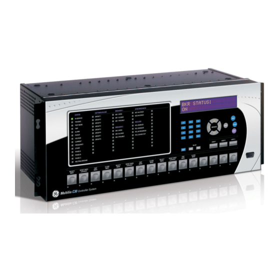
C30 Controller System
UR Series Instruction Manual
C30 Revision: 7.0x
Manual P/N: 1601-0088-Y3 (GEK-113661B)
E83849
LISTED
IND.CONT. EQ.
52TL
834718A2.CDR
GE Multilin's Quality Management
System is registered to ISO
9001:2008
QMI # 005094
UL # A3775
Table of Contents

Related Manuals for GE C30


Summary of Contents for GE C30
- Page 1 Digital Energy C30 Controller System UR Series Instruction Manual C30 Revision: 7.0x Manual P/N: 1601-0088-Y3 (GEK-113661B) 834718A2.CDR E83849 GE Digital Energy LISTED 650 Markland Street IND.CONT. EQ. 52TL Markham, Ontario GE Multilin's Quality Management Canada L6C 0M1 System is registered to ISO...
- Page 2 The contents of this manual are the property of GE Multilin Inc. This documentation is furnished on license and may not be reproduced in whole or in part without the permission of GE Multilin. The content of this manual is for informational use only and is subject to change without notice.
-
Page 3: Table Of Contents
1.3 ENERVISTA UR SETUP SOFTWARE 1.3.1 REQUIREMENTS ....................1-6 1.3.2 INSTALLATION....................1-6 1.3.3 CONFIGURING THE C30 FOR SOFTWARE ACCESS ........1-7 1.3.4 USING THE QUICK CONNECT FEATURE............. 1-10 1.3.5 CONNECTING TO THE C30 RELAY .............. 1-16 1.4 UR HARDWARE 1.4.1 MOUNTING AND WIRING................ - Page 4 USER-PROGRAMMABLE LEDS ..............5-52 5.2.11 USER-PROGRAMMABLE SELF TESTS ............5-55 5.2.12 CONTROL PUSHBUTTONS ................5-57 5.2.13 USER-PROGRAMMABLE PUSHBUTTONS............5-58 5.2.14 FLEX STATE PARAMETERS ................5-63 5.2.15 USER-DEFINABLE DISPLAYS ................5-64 5.2.16 DIRECT INPUTS AND OUTPUTS..............5-66 5.2.17 TELEPROTECTION ..................5-74 5.2.18 INSTALLATION ....................5-74 C30 Controller System GE Multilin...
- Page 5 VIRTUAL OUTPUTS ..................6-5 6.2.8 REMOTE DEVICES ................... 6-5 6.2.9 SELECTOR SWITCHES..................6-6 6.2.10 DIGITAL COUNTERS ..................6-6 6.2.11 FLEX STATES ....................6-6 6.2.12 ETHERNET......................6-6 6.2.13 REAL TIME CLOCK SYNCHRONIZING............6-7 6.2.14 DIRECT INPUTS....................6-8 GE Multilin C30 Controller System...
- Page 6 B.2 MODBUS FUNCTION CODES B.2.1 SUPPORTED FUNCTION CODES ..............B-3 B.2.2 READ ACTUAL VALUES OR SETTINGS (FUNCTION CODE 03/04H) ... B-3 B.2.3 EXECUTE OPERATION (FUNCTION CODE 05H)........... B-4 B.2.4 STORE SINGLE SETTING (FUNCTION CODE 06H)........B-4 C30 Controller System GE Multilin...
- Page 7 ACSI BASIC CONFORMANCE STATEMENT..........C-22 C.6.2 ACSI MODELS CONFORMANCE STATEMENT ..........C-22 C.6.3 ACSI SERVICES CONFORMANCE STATEMENT .........C-23 C.7 LOGICAL NODES C.7.1 LOGICAL NODES TABLE ................C-26 D. IEC 60870-5-104 D.1 IEC 60870-5-104 COMMUNICATIONS D.1.1 INTEROPERABILITY DOCUMENT ..............D-1 D.1.2 POINT LIST......................D-9 GE Multilin C30 Controller System...
- Page 8 E.2.3 COUNTERS..................... E-10 E.2.4 ANALOG INPUTS.................... E-11 F. MISCELLANEOUS F.1 CHANGE NOTES F.1.1 REVISION HISTORY..................F-1 F.1.2 CHANGES TO THE C30 MANUAL ..............F-2 F.2 ABBREVIATIONS F.2.1 STANDARD ABBREVIATIONS ................. F-4 F.3 WARRANTY F.3.1 GE MULTILIN WARRANTY................F-6 INDEX viii...
- Page 9 Ezen termék akkumulátort tartalmaz, amely az Európai Unión belül csak a kijelölt módon és helyen dobható ki. A terméken illetve a mellékelt ismertetőn olvasható a kadmium (Cd), ólom (Pb) vagy higany (Hg) tartalomra utaló betűjelzés. A hulladék akkumulátor leadható a termék forgalmazójánál új akkumulátor vásárlásakor, vagy a kijelölt elektronikai hulladékudvarokban. További információ a www.recyclethis.info oldalon. GE Multilin C30 Controller System...
- Page 10 Batteriet är märkt med denna symbol, vilket kan innebära att det innehåller kadmium (Cd), bly (Pb) eller kvicksilver (Hg). För korrekt återvinning skall batteriet returneras till leverantören eller till en därför avsedd deponering. För mer information, se: www.recyclethis.info. C30 Controller System GE Multilin...
- Page 11 905 294 6222 Latin America +55 11 3614 1700 Europe, Middle East, Africa +(34) 94 485 88 00 Asia +86 21 2401 3208 India +91 80 41314617 From GE Part Number 1604-0021-A1, GE Publication Number GEK-113574 GE Multilin C30 Controller System...
- Page 12 0.1 BATTERY DISPOSAL 0 BATTERY DISPOSAL C30 Controller System GE Multilin...
-
Page 13: Getting Started
1.1 IMPORTANT PROCEDURES 1 GETTING STARTED 1.1IMPORTANT PROCEDURES Read this chapter to help guide you through the initial setup of your new C30 Controller System. 1.1.1 CAUTIONS AND WARNINGS Before attempting to install or use the device, review all safety indicators in this document to help prevent injury, equipment damage, or downtime. -
Page 14: Inspection Checklist
For product information, instruction manual updates, and the latest software updates, visit the GE Digital Energy website at http://www.gedigitalenergy.com. If there is any noticeable physical damage, or any of the contents listed are missing, please contact GE Digital Energy immediately. -
Page 15: Overview
This new generation of equipment is easily incorporated into automation systems, at both the station and enterprise levels. The GE Multilin Uni- versal Relay (UR) series meets these goals. - Page 16 The UR-series devices operate in a cyclic scan fashion. The device reads the inputs into an input status table, solves the logic program (FlexLogic equation), and then sets each output to the appropriate state in an output status table. Any result- ing task execution is priority interrupt-driven. Figure 1–3: UR-SERIES SCAN OPERATION C30 Controller System GE Multilin...
-
Page 17: Ur Software Architecture
Employing OOD/OOP in the software architecture of the C30 achieves the same features as the hardware architecture: modularity, scalability, and flexibility. The application software for any UR-series device (for example, feeder protection, transformer protection, distance protection) is constructed by combining objects from the various functional classes. -
Page 18: Enervista Ur Setup Software
Video capable of displaying 800 x 600 or higher in high-color mode (16-bit color) • RS232 and/or Ethernet port for communications to the relay The following qualified modems have been tested to be compliant with the C30 and the EnerVista UR Setup software: • US Robotics external 56K FaxModem 5686 •... -
Page 19: Configuring The C30 For Software Access
OVERVIEW The user can connect remotely to the C30 through the rear RS485 port or the rear Ethernet port with a computer running the EnerVista UR Setup software. The C30 can also be accessed locally with a laptop computer through the front panel RS232 port or the rear Ethernet port using the Quick Connect feature. - Page 20 An Ethernet module must be specified at the time of ordering. • To configure the C30 for local access with a laptop through either the front RS232 port or rear Ethernet port, see the Using the Quick Connect Feature section.
- Page 21 1.3 ENERVISTA UR SETUP SOFTWARE 10. Click the Read Order Code button to connect to the C30 device and upload the order code. If a communications error occurs, ensure that the EnerVista UR Setup serial communications values entered in the previous step correspond to the relay setting values.
-
Page 22: Using The Quick Connect Feature
USING QUICK CONNECT VIA THE REAR ETHERNET PORTS To use the Quick Connect feature to access the C30 from a computer through Ethernet, first assign an IP address to the relay from the front panel keyboard. Press the MENU key until the SETTINGS menu displays. - Page 23 Now, assign the computer an IP address compatible with the relay’s IP address. From the Windows desktop, right-click the My Network Places icon and select Properties to open the network con- nections window. Right-click the Local Area Connection icon and select Properties. GE Multilin C30 Controller System 1-11...
- Page 24 Select the Internet Protocol (TCP/IP) item from the list, and click the Properties button. Click the “Use the following IP address” box. Enter an IP address with the first three numbers the same as the IP address of the C30 relay and the last number dif- ferent (in this example, 1.1.1.2).
- Page 25 Minimum = 0ms, Maximum = 0ms, Average = 0 ms Pinging 1.1.1.1 with 32 bytes of data: verify the physical connection between the C30 and the laptop computer, and double-check the programmed IP address in the setting, then repeat step 2.
- Page 26 Click the Quick Connect button to open the Quick Connect dialog box. Select the Ethernet interface and enter the IP address assigned to the C30, then click the Connect button. The EnerVista UR Setup software creates a site named “Quick Connect” with a corresponding device also named “Quick Connect”...
- Page 27 Set the computer to “Obtain a relay address automatically” as shown. If this computer is used to connect to the Internet, re-enable any proxy server settings after the computer has been discon- nected from the C30 relay. AUTOMATIC DISCOVERY OF ETHERNET DEVICES The EnerVista UR Setup software can automatically discover and communicate to all UR-series IEDs located on an Ether- net network.
-
Page 28: Connecting To The C30 Relay
The EnerVista UR Setup software has several quick action buttons to provide instant access to several functions that are often performed when using C30 relays. From the online window, users can select the relay to interrogate from a pull-down window, then click the button for the action they want to perform. The following quick action functions are available: •... -
Page 29: Ur Hardware
This device (catalog number F485) connects to the computer using a straight-through serial cable. A shielded twisted-pair (20, 22, or 24 AWG) connects the F485 converter to the C30 rear communications port. The converter terminals (+, –, GND) are connected to the C30 communication module (+, –, COM) terminals. See the CPU communica- tions ports section in chapter 3 for details. -
Page 30: Using The Relay
Not Programmed To put the relay in the “Programmed” state, press either of the VALUE keys once and then press ENTER. The face- plate Trouble LED turns off and the In Service LED turns on. 1-18 C30 Controller System GE Multilin... -
Page 31: Relay Passwords
See the Changing Settings section in Chapter 4 for complete instructions on setting security-level passwords. 1.5.6 FLEXLOGIC CUSTOMIZATION NOTE FlexLogic equation editing is required for setting user-defined logic for customizing the relay operations. See the FlexLogic section in Chapter 5. GE Multilin C30 Controller System 1-19... -
Page 32: Commissioning
As such, no further functional tests are required. The C30 performs a number of continual self-tests and takes the necessary action in case of any major errors (see the Relay Self-tests section in chapter 7). However, it is recommended that C30 maintenance be scheduled with other system maintenance. -
Page 33: Product Description
2.1.2 ORDERING a) OVERVIEW The C30 is available as a 19-inch rack horizontal mount or reduced-size (¾) vertical unit and consists of the following mod- ules: power supply, CPU, CT/VT, digital input and output, transducer input and output, and inter-relay communications. - Page 34 2.1 INTRODUCTION 2 PRODUCT DESCRIPTION b) STANDARD ORDER CODES The order codes for the horizontal mount units are shown below. Table 2–2: C30 ORDER CODES (HORIZONTAL UNITS) * - F - W/X Full Size Horizontal Mount BASE UNIT Base Unit...
- Page 35 2 PRODUCT DESCRIPTION 2.1 INTRODUCTION The order codes for the reduced size vertical mount units are shown below. Table 2–3: C30 ORDER CODES (REDUCED SIZE VERTICAL UNITS) * - F Reduced Size Vertical Mount (see note regarding P/R slot below)
- Page 36 2 PRODUCT DESCRIPTION c) ORDER CODES WITH PROCESS BUS MODULES The order codes for the horizontal mount units with the process bus module are shown below. Table 2–4: C30 ORDER CODES (HORIZONTAL UNITS WITH PROCESS BUS) * - F - W/X...
- Page 37 2.1 INTRODUCTION The order codes for the reduced size vertical mount units with the process bus module are shown below. Table 2–5: C30 ORDER CODES (REDUCED SIZE VERTICAL UNITS WITH PROCESS BUS) * - F Reduced Size Vertical Mount (see note regarding P/R slot below)
-
Page 38: Replacement Modules
Replacement modules can be ordered separately. When ordering a replacement CPU module or faceplate, provide the serial number of your existing unit. Not all replacement modules may be applicable to the C30 relay. Only the modules specified in the order codes are available as replacement modules. - Page 39 CT/VT Standard 4CT/4VT Sensitive Ground 4CT/4VT MODULES Standard 8CT (NOT AVAILABLE FOR THE C30) Standard 4CT/4VT with enhanced diagnostics Standard 8CT with enhanced diagnostics INTER-RELAY COMMUNICATIONS C37.94SM, 1300nm single-mode, ELED, 1 channel single-mode C37.94SM, 1300nm single-mode, ELED, 2 channel single-mode...
-
Page 40: Specifications
Pickup delay: 0.000 to 999999.999 s in steps of 0.001 tual input Dropout delay: 0.000 to 999999.999 s in steps of 0.001 Reset mode: self-reset or latched Timing accuracy: ±3% or ±4 ms, whichever is greater C30 Controller System GE Multilin... -
Page 41: Monitoring
Responding to: Rate of unreturned messages in the ring Accuracy: ±0.2% of full scale configuration Type: Passive Monitoring message count: 10 to 10000 in steps of 1 Alarm threshold: 1 to 1000 in steps of 1 GE Multilin C30 Controller System... -
Page 42: Power Supply
24 V 48 V 1.6 A 125 V 0.4 A 250 V 0.2 A Operate time: < 4 ms Contact material: silver alloy Control: separate operate and reset inputs Control mode: operate-dominant or reset-dominant 2-10 C30 Controller System GE Multilin... - Page 43 3.2 A capability L/R = 10 ms (0 to 250 V 1.6 A 10 A 10 A L/R = 20 ms L/R = 40 ms L/R = 40 ms 0.8 A L/R = 40 ms GE Multilin C30 Controller System 2-11...
-
Page 44: Communications
1300 nm Laser, –1 dBm –30 dBm 29 dB Singlemode 1550 nm Laser, +5 dBm –30 dBm 35 dB Singlemode These power budgets are calculated from the manu- facturer’s worst-case transmitter power and worst NOTE 2-12 C30 Controller System GE Multilin... -
Page 45: Environmental
Operating temperature: –40 to 60°C; the LCD contrast can be Pollution degree: impaired at temperatures less than – Overvoltage category: 20°C Ingress protection: IP20 front, IP10 back HUMIDITY Humidity: operating up to 95% (non-condensing) at 55°C (as per IEC60068-2-30 variant 1, 6 days). GE Multilin C30 Controller System 2-13... -
Page 46: Type Tests
2.2 SPECIFICATIONS 2 PRODUCT DESCRIPTION 2.2.9 TYPE TESTS C30 TYPE TESTS TEST REFERENCE STANDARD TEST LEVEL Dielectric voltage withstand EN60255-5 2.2 kV Impulse voltage withstand EN60255-5 5 kV Damped oscillatory IEC61000-4-18 / IEC60255-22-1 2.5 kV CM, 1 kV DM Electrostatic discharge... -
Page 47: Approvals
To avoid deterioration of electrolytic capacitors, power up units that are stored in a de-energized state once per year, for one hour continuously. GE Multilin C30 Controller System 2-15... - Page 48 2.2 SPECIFICATIONS 2 PRODUCT DESCRIPTION 2-16 C30 Controller System GE Multilin...
-
Page 49: Hardware
HORIZONTAL UNITS The C30 Controller System is available as a 19-inch rack horizontal mount unit with a removable faceplate. The faceplate can be specified as either standard or enhanced at the time of ordering. The enhanced faceplate contains additional user- programmable pushbuttons and LED indicators. - Page 50 VERTICAL UNITS The C30 Controller System is available as a reduced size (¾) vertical mount unit, with a removable faceplate. The face- plate can be specified as either standard or enhanced at the time of ordering. The enhanced faceplate contains additional user-programmable pushbuttons and LED indicators.
- Page 51 RS232 communications port. The relay is secured to the panel with the use of four screws supplied with the relay. 11.015” 7.482” 1.329” 13.560” 15.000” 14.025” 4.000” 9.780” 843809A1.CDR Figure 3–4: C30 VERTICAL DIMENSIONS (ENHANCED PANEL) GE Multilin C30 Controller System...
- Page 52 3.1 DESCRIPTION 3 HARDWARE Figure 3–5: C30 VERTICAL MOUNTING AND DIMENSIONS (STANDARD PANEL) For details on side mounting C30 devices with the enhanced front panel, refer to the following documents available online from the GE Multilin website. • GEK-113180: UR-series UR-V side-mounting front panel assembly instructions.
- Page 53 3 HARDWARE 3.1 DESCRIPTION Figure 3–6: C30 VERTICAL SIDE MOUNTING INSTALLATION (STANDARD PANEL) GE Multilin C30 Controller System...
-
Page 54: Module Withdrawal And Insertion
The enhanced faceplate can be opened to the left, once the thumb screw has been removed, as shown below. This allows for easy accessibility of the modules for withdrawal. The new wide-angle hinge assembly in the enhanced front panel opens completely and allows easy access to all modules in the C30. C30 Controller System... - Page 55 When the clips have locked into position, the module will be fully inserted. CPU modules have 100Base-FX connectors. These connectors must be individually disconnected from the module before it can be removed from the chassis. NOTE NOTE GE Multilin C30 Controller System...
-
Page 56: Rear Terminal Layout
(nearest to CPU module) which is indicated by an arrow marker on the terminal block. See the following figure for an example of rear terminal assignments. Figure 3–11: EXAMPLE OF MODULES IN F AND H SLOTS C30 Controller System GE Multilin... -
Page 57: Wiring
3 HARDWARE 3.2 WIRING 3.2WIRING 3.2.1 TYPICAL WIRING Figure 3–12: TYPICAL WIRING DIAGRAM GE Multilin C30 Controller System... -
Page 58: Dielectric Strength
(see the Self-test errors section in chapter 7) or control power is lost, the relay is de-energize. For high reliability systems, the C30 has a redundant option in which two C30 power supplies are placed in parallel on the bus. -
Page 59: Process Bus Modules
3.2.4 PROCESS BUS MODULES The C30 can be ordered with a process bus interface module. This module is designed to interface with the GE Multilin HardFiber system, allowing bidirectional IEC 61850 fiber optic communications with up to eight HardFiber merging units, known as Bricks. - Page 60 DC voltage source. If the 48 V DC output of the power supply is used as a source, a 500 , 10 W resistor is appropriate. In this configuration, the voltage across either the form-A contact or the resistor can be used to monitor the state of the output. 3-12 C30 Controller System GE Multilin...
- Page 61 2 Inputs Form-C ~6a, ~6c 2 Inputs Fast Form-C ~7a, ~7c 2 Inputs ~7a, ~7c 2 Inputs ~7a, ~7c 2 Inputs Fast Form-C ~8a, ~8c 2 Inputs ~8a, ~8c 2 Inputs ~8a, ~8c 2 Inputs GE Multilin C30 Controller System 3-13...
- Page 62 Not Used ~5a, ~5c 2 Inputs 2 Outputs Solid-State Solid-State ~6a, ~6c 2 Inputs 2 Outputs Not Used Not Used ~7a, ~7c 2 Inputs 2 Outputs Solid-State Solid-State ~8a, ~8c 2 Inputs Not Used 3-14 C30 Controller System GE Multilin...
- Page 63 3 HARDWARE 3.2 WIRING Figure 3–15: CONTACT INPUT AND OUTPUT MODULE WIRING (1 of 2) GE Multilin C30 Controller System 3-15...
- Page 64 CONTACT IN CONTACT IN COMMON SURGE 842763A2.CDR Figure 3–16: CONTACT INPUT AND OUTPUT MODULE WIRING (2 of 2) For proper functionality, observe correct polarity for all contact input and solid state output connec- tions. 3-16 C30 Controller System GE Multilin...
- Page 65 There is no provision in the relay to detect a DC ground fault on 48 V DC control power external output. We recom- mend using an external DC supply. NOTE GE Multilin C30 Controller System 3-17...
- Page 66 CONTACT INPUT 2 AUTO-BURNISH = ON 842751A1.CDR Figure 3–19: AUTO-BURNISH DIP SWITCHES The auto-burnish circuitry has an internal fuse for safety purposes. During regular maintenance, check the auto- burnish functionality using an oscilloscope. NOTE 3-18 C30 Controller System GE Multilin...
-
Page 67: Transducer Inputs/Outputs
3.2.7 RS232 FACEPLATE PORT A 9-pin RS232C serial port is located on the C30 faceplate for programming with a computer. All that is required to use this interface is a computer running the EnerVista UR Setup software provided with the relay. Cabling for the RS232 port is shown in the following figure for both 9-pin and 25-pin connectors. -
Page 68: Cpu Communication Ports
This common voltage is implied to be a power supply common. Some systems allow the shield (drain wire) to be used as common wire and to connect directly to the C30 COM terminal (#3); others function cor- rectly only if the common wire is connected to the C30 COM terminal, but insulated from the shield. - Page 69 62.5 µm for 100 Mbps. For optical power budgeting, splices are required every 1 km for the transmitter/receiver pair. When splicing optical fibers, the diameter and numerical aperture of each fiber must be the same. GE Multilin C30 Controller System 3-21...
-
Page 70: Irig-B
Figure 3–24: OPTIONS FOR THE IRIG-B CONNECTION Using an amplitude modulated receiver causes errors up to 1 ms in event time-stamping. NOTE 3-22 C30 Controller System GE Multilin... -
Page 71: Direct Input/Output Communications
3.3DIRECT INPUT/OUTPUT COMMUNICATIONS 3.3.1 DESCRIPTION The C30 direct inputs and outputs feature makes use of the type 7 series of communications modules, which allow direct messaging between devices. The communications channels are normally connected in a ring configuration as shown in the following figure. The trans- mitter of one module is connected to the receiver of the next module. - Page 72 These modules are listed in the following table. All fiber modules use ST type connectors. Not all the direct input and output communications modules may be applicable to the C30 relay. Only the modules specified in the order codes are available as direct input and output communications modules.
-
Page 73: Fiber: Led And Eled Transmitters
The following figure shows the configuration for the 72, 73, 7D, and 7K fiber-laser module. Figure 3–29: LASER FIBER MODULES When using a laser Interface, attenuators can be necessary to ensure that you do not exceed the maximum optical input power to the receiver. GE Multilin C30 Controller System 3-25... -
Page 74: Interface
Remove the top cover by sliding it towards the rear and then lift it upwards. Set the timing selection switches (channel 1, channel 2) to the desired timing modes. Replace the top cover and the cover screw. 3-26 C30 Controller System GE Multilin... - Page 75 For connection to a higher order system (UR- to-multiplexer, factory defaults), set to octet timing (S1 = ON) and set timing mode to loop timing (S5 = OFF and S6 = OFF). GE Multilin C30 Controller System 3-27...
- Page 76 G.703 line side of the interface while the other lies on the differential Manchester side of the interface. DMR = Differential Manchester Receiver DMX = Differential Manchester Transmitter G7X = G.703 Transmitter G7R = G.703 Receiver 842775A1.CDR Figure 3–34: G.703 DUAL LOOPBACK MODE 3-28 C30 Controller System GE Multilin...
-
Page 77: Rs422 Interface
UR–RS422 channels is synchronized via the send timing leads on data module 1 as shown below. If the terminal timing feature is not available or this type of connection is not desired, the G.703 interface is a viable option that does not impose timing restrictions. GE Multilin C30 Controller System 3-29... - Page 78 Figure 3–37: TIMING CONFIGURATION FOR RS422 TWO-CHANNEL, 3-TERMINAL APPLICATION Data module 1 provides timing to the C30 RS422 interface via the ST(A) and ST(B) outputs. Data module 1 also provides timing to data module 2 TT(A) and TT(B) inputs via the ST(A) and AT(B) outputs. The data module pin numbers have been omitted in the figure above since they vary by manufacturer.
-
Page 79: Rs422 And Fiber Interface
G.703 and fiber interfaces. When using a laser Interface, attenuators can be necessary to ensure that you do not exceed the maximum optical input power to the receiver. Figure 3–40: G.703 AND FIBER INTERFACE CONNECTION GE Multilin C30 Controller System 3-31... -
Page 80: Ieee C37.94 Interface
IEEE C37.94 standard, as shown below. The UR-series C37.94 communication module has six (6) switches that are used to set the clock configuration. The func- tions of these control switches are shown below. 3-32 C30 Controller System GE Multilin... - Page 81 Once the clips have cleared the raised edge of the chassis, engage the clips simultaneously. When the clips have locked into position, the module is fully inserted. Figure 3–41: IEEE C37.94 TIMING SELECTION SWITCH SETTING GE Multilin C30 Controller System 3-33...
- Page 82 • Solid yellow — FPGA is receiving a "yellow bit" and remains yellow for each "yellow bit" • Solid red — FPGA is not receiving a valid packet or the packet received is invalid 3-34 C30 Controller System GE Multilin...
-
Page 83: C37.94Sm Interface
For the internal timing mode, the system clock is generated internally. Therefore, the timing switch selection should be internal timing for relay 1 and loop timed for relay 2. There must be only one timing source configured. GE Multilin C30 Controller System 3-35... - Page 84 Once the clips have cleared the raised edge of the chassis, engage the clips simultaneously. When the clips have locked into position, the module is fully inserted. Figure 3–43: C37.94SM TIMING SELECTION SWITCH SETTING 3-36 C30 Controller System GE Multilin...
- Page 85 • Solid yellow — FPGA is receiving a "yellow bit" and remains yellow for each "yellow bit" • Solid red — FPGA is not receiving a valid packet or the packet received is invalid GE Multilin C30 Controller System 3-37...
- Page 86 3.3 DIRECT INPUT/OUTPUT COMMUNICATIONS 3 HARDWARE 3-38 C30 Controller System GE Multilin...
-
Page 87: Human Interfaces
In online mode, you can communicate with the device in real-time. The EnerVista UR Setup software is provided with every C30 relay and runs on Microsoft Windows 95, 98, NT, 2000, ME, and XP. This chapter provides a summary of the basic EnerVista UR Setup software interface features. The EnerVista UR Setup Help File provides details for getting started and using the EnerVista UR Setup software interface. - Page 88 Site List window are automatically sent to the online communicating device. g) FIRMWARE UPGRADES The firmware of a C30 device can be upgraded, locally or remotely, via the EnerVista UR Setup software. The correspond- ing instructions are provided by the EnerVista UR Setup Help file under the topic “Upgrading Firmware”.
-
Page 89: Enervista Ur Setup Main Window
Device data view windows, with common tool bar Settings file data view windows, with common tool bar Workspace area with data view tabs Status bar 10. Quick action hot links 842786A2.CDR Figure 4–1: ENERVISTA UR SETUP SOFTWARE MAIN WINDOW GE Multilin C30 Controller System... -
Page 90: Extended Enervista Ur Setup Features
Select the Template Mode > Edit Template option to place the device in template editing mode. Enter the template password then click OK. Open the relevant settings windows that contain settings to be specified as viewable. C30 Controller System GE Multilin... - Page 91 The following procedure describes how to add password protection to a settings file template. Select a settings file from the offline window on the left of the EnerVista UR Setup main screen. Selecting the Template Mode > Password Protect Template option. GE Multilin C30 Controller System...
- Page 92 Template Mode > View In Template Mode command. The template specifies that only the Pickup Curve Phase time overcurrent settings window without template applied. settings be available. 842858A1.CDR Figure 4–4: APPLYING TEMPLATES VIA THE VIEW IN TEMPLATE MODE COMMAND C30 Controller System GE Multilin...
- Page 93 Select an installed device or settings file from the tree menu on the left of the EnerVista UR Setup main screen. Select the Template Mode > Remove Settings Template option. Enter the template password and click OK to continue. GE Multilin C30 Controller System...
-
Page 94: Securing And Locking Flexlogic Equations
Click on Save to save and apply changes to the settings template. Select the Template Mode > View In Template Mode option to view the template. Apply a password to the template then click OK to secure the FlexLogic equation. C30 Controller System GE Multilin... - Page 95 FlexLogic entries in a settings file have been secured, use the following procedure to lock the settings file to a specific serial number. Select the settings file in the offline window. Right-click on the file and select the Edit Settings File Properties item. GE Multilin C30 Controller System...
-
Page 96: Settings File Traceability
When a settings file is transferred to a C30 device, the date, time, and serial number of the C30 are sent back to EnerVista UR Setup and added to the settings file on the local PC. This infor- mation can be compared with the C30 actual values at any later date to determine if security has been compromised. - Page 97 4.2 EXTENDED ENERVISTA UR SETUP FEATURES The transfer date of a setting file written to a C30 is logged in the relay and can be viewed via EnerVista UR Setup or the front panel display. Likewise, the transfer date of a setting file saved to a local PC is logged in EnerVista UR Setup.
- Page 98 ONLINE DEVICE TRACEABILITY INFORMATION The C30 serial number and file transfer date are available for an online device through the actual values. Select the Actual Values > Product Info > Model Information menu item within the EnerVista UR Setup online window as shown in the example below.
-
Page 99: Faceplate Interface
LED panel 1 LED panel 2 LED panel 3 Display Front panel RS232 port Small user-programmable User-programmable Keypad (control) pushbuttons 1 to 7 pushbuttons 1 to 12 827801A . Figure 4–16: UR-SERIES STANDARD HORIZONTAL FACEPLATE PANELS GE Multilin C30 Controller System 4-13... -
Page 100: Led Indicators
The status indicators in the first column are described below. • IN SERVICE: This LED indicates that control power is applied, all monitored inputs, outputs, and internal systems are OK, and that the device has been programmed. 4-14 C30 Controller System GE Multilin... - Page 101 PHASE C: This LED indicates phase C was involved. • NEUTRAL/GROUND: This LED indicates that neutral or ground was involved. In the C30 Controller System, only the OTHER indicator is applicable and indicates that a digital element was involved. NOTE The user-programmable LEDs consist of 48 amber LED indicators in four columns.
- Page 102 User customization of LED operation is of maximum benefit in installations where languages other than English are used to communicate with operators. Refer to the User-programmable LEDs section in chapter 5 for the settings used to program the operation of the LEDs on these panels. 4-16 C30 Controller System GE Multilin...
-
Page 103: Custom Labeling Of Leds
EnerVista UR Setup software is installed and operational • The C30 settings have been saved to a settings file • The C30 front panel label cutout sheet (GE Multilin part number 1006-0047) has been downloaded from http://www.gedigitalenergy.com/products/support/ur/URLEDenhanced.doc and printed •... - Page 104 Enter the text to appear next to each LED and above each user-programmable pushbuttons in the fields provided. Feed the C30 front panel label cutout sheet into a printer and press the Print button in the front panel report window.
- Page 105 4.3 FACEPLATE INTERFACE Bend the tab at the center of the tool tail as shown below. The following procedure describes how to remove the LED labels from the C30 enhanced front panel and insert the custom labels. Use the knife to lift the LED label and slide the label tool underneath. Make sure the bent tabs are pointing away from the relay.
- Page 106 Slide the new LED label inside the pocket until the text is properly aligned with the LEDs, as shown below. The following procedure describes how to remove the user-programmable pushbutton labels from the C30 enhanced front panel and insert the custom labels.
- Page 107 Slide the label tool under the user-programmable pushbutton label until the tabs snap out as shown below. This attaches the label tool to the user-programmable pushbutton label. Remove the tool and attached user-programmable pushbutton label as shown below. GE Multilin C30 Controller System 4-21...
- Page 108 The panel templates provide relative LED locations and located example text (x) edit boxes. The following procedure demonstrates how to install/uninstall the custom panel labeling. Remove the clear Lexan Front Cover (GE Multilin part number: 1501-0014). Push in...
-
Page 109: Display
INTRODUCTION The C30 can interface with associated circuit breakers. In many cases the application monitors the state of the breaker, that can be presented on faceplate LEDs, along with a breaker trouble indication. Breaker operations can be manually initiated from faceplate keypad or automatically initiated from a FlexLogic operand. -
Page 110: Menus
Press the MENU key to select a header display page (top-level menu). The header title appears momentarily followed by a header display page menu item. Each press of the MENU key advances through the following main heading pages: • Actual values • Settings • Commands • Targets • User displays (when enabled) 4-24 C30 Controller System GE Multilin... - Page 111 FLASH MESSAGE Properties. TIME: 1.0 s To view the remaining settings associated with the Display Properties subheader, DEFAULT MESSAGE repeatedly press the MESSAGE DOWN key. The last message appears as shown. INTENSITY: 25% GE Multilin C30 Controller System 4-25...
-
Page 112: Changing Settings
ENTERING ALPHANUMERIC TEXT Text settings have data values which are fixed in length, but user-defined in character. They can be upper case letters, lower case letters, numerals, and a selection of special characters. 4-26 C30 Controller System GE Multilin... -
Page 113: Settings
When the "NEW SETTING HAS BEEN STORED" message appears, the relay is in "Programmed" state and the In Service LED turns on. e) ENTERING INITIAL PASSWORDS The C30 supports password entry from a local or remote connection. GE Multilin C30 Controller System... - Page 114 When an incorrect command or setting password has been entered via the faceplate interface three times within a 3-minute time span, the FlexLogic operand is set to “On” and the C30 does not allow settings or command LOCAL ACCESS DENIED...
- Page 115 FlexLogic operand is set to “On” and the REMOTE ACCESS DENIED C30 does not allow Settings or Command access via the any external communications interface for the next ten minutes. FlexLogic operand is set to “Off” after the expiration of the ten-minute timeout.
- Page 116 4.3 FACEPLATE INTERFACE 4 HUMAN INTERFACES 4-30 C30 Controller System GE Multilin...
-
Page 117: Overview
INSTALLATION See page 5-74. SETTINGS BREAKERS See page 5-77. SYSTEM SETUP SWITCHES See page 5-81. SETTINGS FLEXLOGIC See page 5-96. FLEXLOGIC EQUATION EDITOR GE Multilin C30 Controller System... - Page 118 REMOTE OUTPUTS See page 5-127. UserSt BIT PAIRS RESETTING See page 5-127. DIRECT INPUTS See page 5-128. DIRECT OUTPUTS See page 5-128. TELEPROTECTION See page 5-132. C30 Controller System GE Multilin...
- Page 119 See page 5-139. SETTINGS TEST MODE See page 5-141. TESTING FUNCTION: Disabled TEST MODE FORCING: See page 5-141. FORCE CONTACT See page 5-142. INPUTS FORCE CONTACT See page 5-143. OUTPUTS GE Multilin C30 Controller System...
-
Page 120: Introduction To Elements
The DPO event is created when the measure and decide comparator output transits from the pickup state (logic 1) to the dropout state (logic 0). This could happen when the element is in the operate state if the reset delay time is not 0. C30 Controller System GE Multilin... -
Page 121: Product Setup
When entering a settings or command password via EnerVista or any serial interface, the user must enter the correspond- ing connection password. If the connection is to the back of the C30, the remote password must be used. If the connection is to the RS232 port of the faceplate, the local password must be used. - Page 122 The remote password settings are only visible from a remote connection via the EnerVista UR Setup software. Select the Settings > Product Setup > Password Security menu item to open the remote password settings window. C30 Controller System GE Multilin...
- Page 123 INVALID ATTEMPTS BEFORE LOCKOUT The C30 provides a means to raise an alarm upon failed password entry. Should password verification fail while accessing a password-protected level of the relay (either settings or commands), the FlexLogic operand is UNAUTHORIZED ACCESS asserted.
- Page 124 When this timer expires, local setting access is ACCESS AUTH TIMEOUT immediately denied. If access is permitted and an off-to-on transition of the FlexLogic operand is detected, the timeout is restarted. The status of this timer is updated every 5 seconds. C30 Controller System GE Multilin...
-
Page 125: Cybersentry Security
Ethernet-to-RS485 gateway is not supported. Because these gateways do not support the secure protocols necessary to communicate with such devices, the connection cannot be established. Use the device as a non-CyberSentry device. GE Multilin C30 Controller System... -
Page 126
UR device for successful authentication, and the shortname is a short, optional alias that can be used in place of the IP address. client 10.0.0.2/24 { secret = testing123 shortname = private-network-1 e. In the
\etc\raddb folder, create a file called dictionary.ge and add the following content. # ########################################################## # GE VSA's ############################################################ VENDOR... - Page 127 Set up the RADIUS client on the UR as follows. Access Device > Settings > Product Setup > Security. Configure the IP address and ports for the RADIUS server. Leave the GE vendor ID field at the default of 2910. Update the RADIUS shared secret as specified in the CLIENTS.CONF file.
- Page 128 Observer role requires a password. • The default password is “ChangeMe1#”. • Once the passwords are set, the Administrator with Supervisor approval can change the role associated password. • In CyberSentry, password encryption is not supported. 5-12 C30 Controller System GE Multilin...
- Page 129 Disabled Range: Enabled, Disabled FACTORY SERVICE: MESSAGE MODE: Disabled SELF TESTS See below MESSAGE Range: Enabled, Disabled SUPERVISOR ROLE: MESSAGE Disabled Range: 1 to 9999 minutes SERIAL INACTIVITY MESSAGE TIMEOUT: 1 min GE Multilin C30 Controller System 5-13...
- Page 130 Example: If this setting is "Yes" and an attempt is made to change settings or upgrade the firmware, the UR device denies the setting changes and denies upgrading the firmware. If this setting is "No", the UR device accepts setting changes and firmware upgrade. This role is disabled by default. 5-14 C30 Controller System GE Multilin...
- Page 131 Settings Lock: If this setting is Enabled then an unauthorized write attempt to a setting for a given role activates this self test. PATH: SETTINGS PRODUCT SETUP SECURITY SUPERVISORY SELF TESTS FAILED AUTHENTICATE Range: Enabled, Disabled FAILED FAILED AUTHENTICATE: AUTHENTICATE Enabled GE Multilin C30 Controller System 5-15...
-
Page 132: Display Properties
Some customers prefer very low currents to display as zero, while others prefer the current be displayed even when the value reflects noise rather than the actual signal. The C30 applies a cut- off value to the magnitudes and angles of the measured currents. -
Page 133: Clear Relay Records
Selected records can be cleared from user-programmable conditions with FlexLogic operands. Assigning user-programma- ble pushbuttons to clear specific records are typical applications for these commands. Since the C30 responds to rising edges of the configured FlexLogic operands, they must be asserted for at least 50 ms to take effect. -
Page 134: Communications
0 ms The C30 is equipped with up to two independent serial communication ports. The faceplate RS232 port is intended for local use and is fixed at 19200 baud and no parity. The rear COM2 port is RS485. The RS485 port has settings for baud rate and parity. - Page 135 The topology shown in the following figure allows communications to SCADA, local configuration/monitoring through EnerVista, and access to the public network shared on the same LAN. No redundancy is provided. Figure 5–2: NETWORK CONFIGURATION FOR SINGLE LAN GE Multilin C30 Controller System 5-19...
- Page 136 LAN2, to which port 2 (P2) is connected and communications with SCADA on LAN3, to which port 3 (P3) is connected. There is no redundancy. Figure 5–4: MULTIPLE LANS, NO REDUNDANCY 5-20 C30 Controller System GE Multilin...
- Page 137 When any TCP/UDP port number or any user map setting (when used with DNP) is changed, it becomes active when power to the relay has been cycled (off-on). NOTE GE Multilin C30 Controller System 5-21...
- Page 138 MODBUS SLAVE ADDRESS RS485 port, each C30 must have a unique address from 1 to 254. Address 0 is the broadcast address which all Modbus slave devices listen to. Addresses do not have to be sequential, but no two devices can have the same address or conflicts resulting in errors will occur.
- Page 139 DEFAULT VARIATION: 1 Range: 0 to 32 in steps of 1 DNP NUMBER OF PAIRED MESSAGE CONTROL POINTS: 0 Range: 10 to 7200 s in steps of 1 DNP TCP CONNECTION MESSAGE TIMEOUT: 120 s GE Multilin C30 Controller System 5-23...
- Page 140 DNP analog input points that are voltages will be returned with values 1000 times smaller (for example, a value of 72000 V on the C30 will be returned as 72). These settings are useful when analog input values must be adjusted to fit within cer- tain ranges in DNP masters.
- Page 141 When the DNP data points (analog inputs and/or binary inputs) are configured for Ethernet-enabled relays, check the “DNP Points Lists” C30 web page to view the points lists. This page can be viewed with a web browser by enter- ing the C30 IP address to access the C30 “Main Menu”, then by selecting the “Device Information Menu” > “DNP NOTE Points Lists”...
- Page 142 60870-5-104 point lists must be in one continuous block, any points assigned after the first “Off” point are ignored. NOTE Changes to the DNP / IEC 60870-5-104 point lists will not take effect until the C30 is restarted. NOTE 5-26...
- Page 143 The C30 supports the Manufacturing Message Specification (MMS) protocol as specified by IEC 61850. MMS is supported over two protocol stacks: TCP/IP over Ethernet. The C30 operates as an IEC 61850 server. The Remote inputs and outputs section in this chapter describe the peer-to-peer GSSE/GOOSE message scheme.
- Page 144 IEC 61850 GSSE application ID name string sent as part of each GSSE message. This GSSE ID string identifies the GSSE message to the receiving device. In C30 releases previous to 5.0x, this name string was repre- sented by the setting.
- Page 145 DESTINATION MAC address; the least significant bit of the first byte must be set. In C30 releases previous to 5.0x, the destination Ethernet MAC address was determined automatically by taking the sending MAC address (that is, the unique, local MAC address of the C30) and setting the multicast bit.
- Page 146 The C30 has the ability of detecting if a data item in one of the GOOSE datasets is erroneously oscillating. This can be caused by events such as errors in logic programming, inputs improperly being asserted and de-asserted, or failed station components.
- Page 147 Configure the transmission dataset. Configure the GOOSE service settings. Configure the data. The general steps required for reception configuration are: Configure the reception dataset. Configure the GOOSE service settings. Configure the data. GE Multilin C30 Controller System 5-31...
- Page 148 MMXU1 HZ DEADBAND change greater than 45 mHz, from the previous MMXU1.MX.mag.f value, in the source frequency. The C30 must be rebooted (control power removed and re-applied) before these settings take effect. The following procedure illustrates the reception configuration. Configure the reception dataset by making the following changes in the ...
- Page 149 IEC61850 GOOSE ANALOG INPUT 1 UNITS The GOOSE analog input 1 can now be used as a FlexAnalog value in a FlexElement or in other settings. The C30 must be rebooted (control power removed and re-applied) before these settings take effect.
- Page 150 DNA and UserSt bit pairs that are included in GSSE messages. To set up a C30 to receive a configurable GOOSE dataset that contains two IEC 61850 single point status indications, the following dataset items can be selected (for example, for configurable GOOSE dataset 1): “GGIO3.ST.Ind1.stVal” and “GGIO3.ST.Ind2.stVal”.
- Page 151 CPU resources. When server scanning is disabled, there will be not updated to the IEC 61850 logical node sta- tus values in the C30. Clients will still be able to connect to the server (C30 relay), but most data values will not be updated.
- Page 152 (_) character, and the first character in the prefix must be a letter. This conforms to the IEC 61850 standard. Changes to the logical node prefixes will not take effect until the C30 is restarted. The main menu for the IEC 61850 MMXU deadbands is shown below.
- Page 153 The GGIO2 control configuration settings are used to set the control model for each input. The available choices are “0” (status only), “1” (direct control), and “2” (SBO with normal security). The GGIO2 control points are used to control the C30 virtual inputs.
- Page 154 GGIO1 (binary status values). The settings allow the selection of FlexInteger values for each GGIO5 integer value point. It is intended that clients use GGIO5 to access generic integer values from the C30. Additional settings are provided to allow the selection of the number of integer values available in GGIO5 (1 to 16), and to assign FlexInteger values to the GGIO5 integer inputs.
- Page 155 ITEM 64 attributes supported by the C30. Changes to the dataset will only take effect when the C30 is restarted. It is recommended to use reporting service from logical node LLN0 if a user needs some (but not all) data from already existing GGIO1, GGIO4, and MMXU4 points and their quantity is not greater than 64 minus the number items in this dataset.
- Page 156 Menu”. Web pages are available showing DNP and IEC 60870-5-104 points lists, Modbus registers, event records, fault reports, and so on. First connect the UR and a computer to an Ethernet network, then enter the IP address of the C30 into the “Address”...
- Page 157 NUMBER: The Trivial File Transfer Protocol (TFTP) can be used to transfer files from the C30 over a network. The C30 operates as a TFTP server. TFTP client software is available from various sources, including Microsoft Windows NT. The dir.txt file obtained from the C30 contains a list and description of all available files (event records, oscillography, etc.).
- Page 158 M_ME_NC_1 analog point. Whenever power is removed and re-applied to the C30, the default thresholds are in effect. setting decides whether multiple client connections are accepted or not. If redundancy is set to Yes, IEC REDUNDANCY two simultaneous connections can be active at any given time.
- Page 159 MESSAGE (Modbus register address range) Fast exchanges (50 to 1000 ms) are generally used in control schemes. The C30 has one fast exchange (exchange 1) and two slow exchanges (exchange 2 and 3). The settings menu for the slow EGD exchanges is shown below: ...
-
Page 160: Modbus User Map
EXCH 1 DATA ITEM 1 to 20/50: These settings specify the data items that are part of this EGD exchange. Almost any data from the C30 memory map can be configured to be included in an EGD exchange. The settings are the starting Modbus register address for the data item in decimal format. - Page 161 The relay implements PTP according to IEEE Std 1588 2008 and the equivalent IEC 61588:2009(E), sometimes referred to as version 2 PTP. It does not support the previous version of the standard (version 1). NOTE GE Multilin C30 Controller System 5-45...
- Page 162 With the strict power profile setting enabled, the relay will only select as master clocks displaying the IEEE_C37_238 identification codes. It will use a port only when the peer delay mechanism is operational. With the strict power profile 5-46 C30 Controller System GE Multilin...
- Page 163 The C30 supports the Simple Network Time Protocol specified in RFC-2030. With SNTP, the C30 can obtain clock time over an Ethernet network. The C30 acts as an SNTP client to receive time values from an SNTP/NTP server, usually a ded- icated product using a GPS receiver to provide an accurate time.
- Page 164 DST rules of the local time zone. DAYLIGHT SAVINGS TIME (DST) Note that when IRIG-B time synchronization is active, the local time in the IRIG-B signal contains any daylight savings time offset and so the DST settings are ignored. 5-48 C30 Controller System GE Multilin...
-
Page 165: Oscillography
64 samples per cycle; that is, it has no effect on the fundamental calculations of the device. When changes are made to the oscillography settings, all existing oscillography records will be CLEARED. NOTE GE Multilin C30 Controller System 5-49... - Page 166 IB signal on terminal 2 of the CT/VT module in slot F. If there are no CT/VT modules and analog input modules, no analog traces will appear in the file; only the digital traces will appear. 5-50 C30 Controller System GE Multilin...
-
Page 167: Data Logger
490920 s 436380 s 254460 s 3600000 ms 2727.5 235645200 s 340.9 29455200 s 26182800 s Changing any setting affecting data logger operation will clear any data that is currently in the log. NOTE GE Multilin C30 Controller System 5-51... -
Page 168: User-Programmable Leds
When enabled, the LED test can be initiated from any digital input or user-programmable condition such as user-program- mable pushbutton. The control operand is configured under the setting. The test covers all LEDs, LED TEST CONTROL including the LEDs of the optional user-programmable pushbuttons. The test consists of three stages. 5-52 C30 Controller System GE Multilin... - Page 169 Assume one needs to check if any of the LEDs is “burned” through user-programmable pushbutton 1. The following set- tings should be applied. Configure user-programmable pushbutton 1 by making the following entries in the SETTINGS menu: PRODUCT SETUP USER-PROGRAMMABLE PUSHBUTTONS USER PUSHBUTTON 1 GE Multilin C30 Controller System 5-53...
- Page 170 “Latched”, the LED, once lit, remains so until reset by the faceplate RESET button, from a remote device via a communica- tions channel, or from any programmed operand, even if the LED operand state de-asserts. 5-54 C30 Controller System GE Multilin...
-
Page 171: User-Programmable Self Tests
Range: Disabled, Enabled. SFP MODULE FAIL MESSAGE FUNCTION: Disabled All major self-test alarms are reported automatically with their corresponding FlexLogic operands, events, and targets. Most of the minor alarms can be disabled if desired. GE Multilin C30 Controller System 5-55... - Page 172 ANY MINOR ALARM ANY SELF-TEST mode, minor alarms continue to function along with other major and minor alarms. Refer to the Relay self-tests section in chapter 7 for additional information on major and minor self-test alarms. 5-56 C30 Controller System GE Multilin...
-
Page 173: Control Pushbuttons
The location of the control pushbuttons are shown in the following figures. Control pushbuttons 842813A1.CDR Figure 5–6: CONTROL PUSHBUTTONS (ENHANCED FACEPLATE) An additional four control pushbuttons are included on the standard faceplate when the C30 is ordered with the twelve user-programmable pushbutton option. STATUS EVENT CAUSE... -
Page 174: User-Programmable Pushbuttons
Range: 0 to 60.00 s in steps of 0.05 PUSHBTN 1 DROP-OUT MESSAGE TIME: 0.00 s Range: FlexLogic operand PUSHBTN 1 LED CTL: MESSAGE Range: Disabled, Normal, High Priority PUSHBTN 1 MESSAGE: MESSAGE Disabled Range: Disabled, Enabled PUSHBUTTON 1 MESSAGE EVENTS: Disabled 5-58 C30 Controller System GE Multilin... - Page 175 The pushbutton is reset (deactivated) in latched mode by asserting the operand assigned to the set- PUSHBTN 1 RESET ting or by directly pressing the associated active front panel pushbutton. GE Multilin C30 Controller System 5-59...
- Page 176 This timer is reset upon release of the pushbutton. Note that any pushbutton operation will require the pushbutton to be pressed a minimum of 50 ms. This minimum time is required prior to activating the pushbutton hold timer. 5-60 C30 Controller System GE Multilin...
- Page 177 “Normal” if the setting is “High Priority” or “Normal”. PUSHBTN 1 MESSAGE • PUSHBUTTON 1 EVENTS: If this setting is enabled, each pushbutton state change will be logged as an event into event recorder. GE Multilin C30 Controller System 5-61...
- Page 178 Off = 0 SETTING SETTING Autoreset Delay Autoreset Function = Enabled = Disabled SETTING Drop-Out Timer TIMER FLEXLOGIC OPERAND 200 ms PUSHBUTTON 1 ON 842021A3.CDR Figure 5–11: USER-PROGRAMMABLE PUSHBUTTON LOGIC (Sheet 1 of 2) 5-62 C30 Controller System GE Multilin...
-
Page 179: Flex State Parameters
PATH: SETTINGS PRODUCT SETUP FLEX STATE PARAMETERS Range: FlexLogic operand FLEX STATE PARAMETER PARAMETERS Range: FlexLogic operand PARAMETER MESSAGE Range: FlexLogic operand PARAMETER MESSAGE Range: FlexLogic operand PARAMETER 256: MESSAGE GE Multilin C30 Controller System 5-63... -
Page 180: User-Definable Displays
INVOKE AND SCROLL play, not at the first user-defined display. The pulses must last for at least 250 ms to take effect. INVOKE AND SCROLL 5-64 C30 Controller System GE Multilin... - Page 181 While viewing a user display, press the ENTER key and then select the ‘Yes” option to remove the display from the user display list. Use the MENU key again to exit the user displays menu. GE Multilin C30 Controller System 5-65...
- Page 182 See page 5–72. MESSAGE CRC ALARM CH2 See page 5–72. MESSAGE UNRETURNED See page 5–73. MESSAGE MESSAGES ALARM CH1 UNRETURNED See page 5–73. MESSAGE MESSAGES ALARM CH2 5-66 C30 Controller System GE Multilin...
-
Page 183: Direct Inputs And Outputs
Delivery time for direct input and output messages is approximately 0.2 of a power system cycle at 128 kbps and 0.4 of a power system cycle at 64 kbps, per each ‘bridge’. GE Multilin C30 Controller System 5-67... - Page 184 The following application examples illustrate the basic concepts for direct input and output configuration. Please refer to the Inputs and outputs section in this chapter for information on configuring FlexLogic operands (flags, bits) to be exchanged. 5-68 C30 Controller System GE Multilin...
- Page 185 UR-series chassis. The problem is solved by adding an extra UR-series IED, such as the C30, to satisfy the additional input and output and programmable logic requirements. The two IEDs are connected via single-channel digital communication cards as shown in the figure below.
- Page 186 The complete application requires addressing a number of issues such as failure of both the communications rings, failure or out-of-service conditions of one of the relays, etc. Self-monitoring flags of the direct inputs and outputs feature would be primarily used to address these concerns. 5-70 C30 Controller System GE Multilin...
- Page 187 Inputs and outputs section. A blocking pilot-aided scheme should be implemented with more security and, ideally, faster message delivery time. This could be accomplished using a dual-ring configuration as shown below. GE Multilin C30 Controller System 5-71...
- Page 188 EVENTS: Disabled The C30 checks integrity of the incoming direct input and output messages using a 32-bit CRC. The CRC alarm function is available for monitoring the communication medium noise by tracking the rate of messages failing the CRC check. The monitoring function counts all incoming messages, including messages that failed the CRC check.
- Page 189 MESSAGE EVENTS: Disabled The C30 checks integrity of the direct input and output communication ring by counting unreturned messages. In the ring configuration, all messages originating at a given device should return within a pre-defined period of time. The unreturned messages alarm function is available for monitoring the integrity of the communication ring by tracking the rate of unre- turned messages.
-
Page 190: Teleprotection
TERMINAL 1 ID NUMBER 5.2.18 INSTALLATION PATH: SETTINGS PRODUCT SETUP INSTALLATION Range: Not Programmed, Programmed INSTALLATION RELAY SETTINGS: Not Programmed Range: up to 20 alphanumeric characters RELAY NAME: MESSAGE Relay-1 5-74 C30 Controller System GE Multilin... - Page 191 "Programmed" state. UNIT NOT PROGRAMMED setting allows the user to uniquely identify a relay. This name will appear on generated reports. RELAY NAME GE Multilin C30 Controller System 5-75...
-
Page 192: Remote Resources Configuration
Bricks. Remote resources settings configure the point-to-point connection between specific fiber optic ports on the C30 process card and specific Brick. The relay is then configured to measure spe- cific currents, voltages and contact inputs from those Bricks, and to control specific outputs. -
Page 193: System Setup
0.000 s Range: 0.000 to 65.535 s in steps of 0.001 MANUAL CLOSE RECAL1 MESSAGE TIME: 0.000 s Range: FlexLogic operand BREAKER 1 OUT OF SV: MESSAGE Range: Disabled, Enabled BREAKER 1 EVENTS: MESSAGE Disabled GE Multilin C30 Controller System 5-77... - Page 194 1. The number of breaker control elements is dependent on the number of CT/VT modules specified with the C30. The follow- ing settings are available for each breaker control element.
- Page 195 5 SETTINGS 5.4 SYSTEM SETUP Figure 5–20: DUAL BREAKER CONTROL SCHEME LOGIC (Sheet 1 of 2) IEC 61850 functionality is permitted when the C30 is in “Programmed” mode and not in the local control mode. NOTE GE Multilin C30 Controller System...
- Page 196 5.4 SYSTEM SETUP 5 SETTINGS Figure 5–21: DUAL BREAKER CONTROL SCHEME LOGIC (Sheet 2 of 2) 5-80 C30 Controller System GE Multilin...
-
Page 197: Disconnect Switches
For greater security in determination of the switch pole position, both the 89/a and 89/b auxiliary contacts are used with reporting of the discrepancy between them. The number of available disconnect switches depends on the number of the CT/VT modules ordered with the C30. •... - Page 198 SWITCH 1 ALARM DELAY: This setting specifies the delay interval during which a disagreement of status among the three-pole position tracking operands will not declare a pole disagreement. This allows for non-simultaneous operation of the poles. IEC 61850 functionality is permitted when the C30 is in “Programmed” mode and not in the local control mode. NOTE 5-82...
- Page 199 5 SETTINGS 5.4 SYSTEM SETUP Figure 5–22: DISCONNECT SWITCH SCHEME LOGIC GE Multilin C30 Controller System 5-83...
-
Page 200: Flexlogic
Figure 5–23: UR ARCHITECTURE OVERVIEW The states of all digital signals used in the C30 are represented by flags (or FlexLogic operands, which are described later in this section). A digital “1” is represented by a 'set' flag. Any external contact change-of-state can be used to block an ele- ment from operating, as an input to a control feature in a FlexLogic equation, or to operate a contact output. - Page 201 Some types of operands are present in the relay in multiple instances; e.g. contact and remote inputs. These types of oper- ands are grouped together (for presentation purposes only) on the faceplate display. The characteristics of the different types of operands are listed in the table below. Table 5–6: C30 FLEXLOGIC OPERAND TYPES OPERAND TYPE STATE...
- Page 202 5.5 FLEXLOGIC 5 SETTINGS The operands available for this relay are listed alphabetically by types in the following table. Table 5–7: C30 FLEXLOGIC OPERANDS (Sheet 1 of 4) OPERAND TYPE OPERAND SYNTAX OPERAND DESCRIPTION CONTROL CONTROL PUSHBTN 1 ON Control pushbutton 1 is being pressed...
- Page 203 5 SETTINGS 5.5 FLEXLOGIC Table 5–7: C30 FLEXLOGIC OPERANDS (Sheet 2 of 4) OPERAND TYPE OPERAND SYNTAX OPERAND DESCRIPTION ELEMENT: Dig Element 1 PKP Digital Element 1 is picked up Digital elements Dig Element 1 OP Digital Element 1 is operated...
- Page 204 5.5 FLEXLOGIC 5 SETTINGS Table 5–7: C30 FLEXLOGIC OPERANDS (Sheet 3 of 4) OPERAND TYPE OPERAND SYNTAX OPERAND DESCRIPTION ELEMENT: TELEPRO INPUT 1-1 On Flag is set, Logic =1 Teleprotection inputs/outputs TELEPRO INPUT 1-16 On Flag is set, Logic =1...
- Page 205 5 SETTINGS 5.5 FLEXLOGIC Table 5–7: C30 FLEXLOGIC OPERANDS (Sheet 4 of 4) OPERAND TYPE OPERAND SYNTAX OPERAND DESCRIPTION LED INDICATORS: LED TEST IN PROGRESS An LED test has been initiated and has not finished. LED test LED INDICATORS: LED USER 1 Asserted when user-programmable LED 1 is on.
-
Page 206: Flexlogic Rules
A timer operator (for example, "TIMER 1") or virtual output assignment (for example, " = Virt Op 1") may only be used once. If this rule is broken, a syntax error will be declared. 5-90 C30 Controller System GE Multilin... -
Page 207: Flexlogic Evaluation
(i.e. Virtual Output 3). The final output must also be assigned to a virtual output as virtual output 4, which will be programmed in the contact output section to oper- ate relay H1 (that is, contact output H1). GE Multilin C30 Controller System 5-91... - Page 208 Until accustomed to using FlexLogic, it is suggested that a worksheet with a series of cells marked with the arbitrary parameter numbers be prepared, as shown below. 5-92 C30 Controller System GE Multilin...
- Page 209 99: The final output of the equation is virtual output 4 which is parameter “= Virt Op 4". 98: The operator preceding the output is timer 2, which is operand “TIMER 2". Note that the settings required for the timer are established in the timer programming section. GE Multilin C30 Controller System 5-93...
- Page 210 It is now possible to check that the selection of parameters will produce the required logic by converting the set of parame- ters into a logic diagram. The result of this process is shown below, which is compared to the logic for virtual output 4 dia- gram as a check. 5-94 C30 Controller System GE Multilin...
- Page 211 In the expression above, the virtual output 4 input to the four-input OR is listed before it is created. This is typical of a form of feedback, in this case, used to create a seal-in effect with the latch, and is correct. GE Multilin C30 Controller System 5-95...
-
Page 212: Flexlogic Equation Editor
TIMER 1 PICKUP DELAY: Sets the time delay to pickup. If a pickup delay is not required, set this function to "0". • TIMER 1 DROPOUT DELAY: Sets the time delay to dropout. If a dropout delay is not required, set this function to "0". 5-96 C30 Controller System GE Multilin... -
Page 213: Flexelements
The element can be programmed to respond either to a signal level or to a rate-of-change (delta) over a pre-defined period of time. The output operand is asserted when the operating signal is higher than a threshold or lower than a threshold as per user's choice. GE Multilin C30 Controller System 5-97... - Page 214 The FLEXELEMENT 1 DIRECTION following figure explains the application of the FLEXELEMENT 1 DIRECTION FLEXELEMENT 1 PICKUP FLEXELEMENT 1 HYS- settings. TERESIS 5-98 C30 Controller System GE Multilin...
- Page 215 FLEXELEMENT DIRECTION = Under; FLEXELEMENT INPUT MODE = Signed; FlexElement 1 OpSig FLEXELEMENT 1 PKP FLEXELEMENT DIRECTION = Under; FLEXELEMENT INPUT MODE = Absolute; FlexElement 1 OpSig 842706A2.CDR Figure 5–33: FLEXELEMENT INPUT MODE SETTING GE Multilin C30 Controller System 5-99...
- Page 216 “Delta”. FLEXELEMENT 1 COMP MODE This setting specifies the pickup delay of the element. The setting FLEXELEMENT 1 PKP DELAY FLEXELEMENT 1 RST DELAY specifies the reset delay of the element. 5-100 C30 Controller System GE Multilin...
-
Page 217: Non-Volatile Latches
FLEXLOGIC OPERANDS Off=0 LATCH 1 ON Dominant LATCH 1 OFF Previous Previous SETTING State State LATCH 1 SET: Off=0 RESET 842005A1.CDR Figure 5–34: NON-VOLATILE LATCH OPERATION TABLE (N = 1 to 16) AND LOGIC GE Multilin C30 Controller System 5-101... -
Page 218: Control Elements
Upon power-up, either the previous position is restored or the relay synchronizes to the current three-bit word (user set- ting). Basic alarm functionality alerts the user under abnormal conditions; for example, the three-bit control input being out of range. 5-102 C30 Controller System GE Multilin... - Page 219 The change is automatic and does not require explicit confirmation to change the selector position. When set to “Acknowledge”, the selector changes its posi- GE Multilin C30 Controller System 5-103...
- Page 220 The selector position pre-selected via the stepping up control input has not been confirmed before the time out. SELECTOR 1 BIT ALARM The selector position pre-selected via the three-bit control input has not been confirmed before the time out. 5-104 C30 Controller System GE Multilin...
- Page 221 3BIT A1 3BIT A2 POS 1 POS 2 POS 3 POS 4 POS 5 POS 6 POS 7 BIT 0 BIT 1 BIT 2 STP ALARM BIT ALARM ALARM 842737A1.CDR Figure 5–35: TIME-OUT MODE GE Multilin C30 Controller System 5-105...
- Page 222 Make the following changes to selector switch element in the SETTINGS CONTROL ELEMENTS SELECTOR SWITCH menu to assign control to user programmable pushbutton 1 and contact inputs 1 through 3: SELECTOR SWITCH 1 5-106 C30 Controller System GE Multilin...
- Page 223 3-bit acknowledge SELECTOR 1 BIT ALARM 3-bit position out SELECTOR 1 ALARM SELECTOR 1 PWR ALARM SELECTOR 1 BIT 0 SELECTOR 1 BIT 1 SELECTOR 1 BIT 2 842012A2.CDR Figure 5–37: SELECTOR SWITCH LOGIC GE Multilin C30 Controller System 5-107...
-
Page 224: Digital Elements
Some versions of the digital input modules include an active voltage monitor circuit connected across form-A contacts. The voltage monitor circuit limits the trickle current through the output circuit (see technical specifications for form-A). 5-108 C30 Controller System GE Multilin... - Page 225 The settings to use digital element 1 to monitor the breaker trip circuit are indicated below (EnerVista UR Setup example shown): The PICKUP DELAY setting should be greater than the operating time of the breaker to avoid nuisance alarms. NOTE GE Multilin C30 Controller System 5-109...
- Page 226 “Off”. In this case, the settings are as follows (EnerVista UR Setup example shown). Figure 5–40: TRIP CIRCUIT EXAMPLE 2 The wiring connection for two examples above is applicable to both form-A contacts with voltage monitoring and solid-state contact with voltage monitoring. NOTE 5-110 C30 Controller System GE Multilin...
-
Page 227: Digital Counters
–2,147,483,648 counts, the counter will rollover to +2,147,483,647. • COUNTER 1 BLOCK: Selects the FlexLogic operand for blocking the counting operation. All counter operands are blocked. GE Multilin C30 Controller System 5-111... - Page 228 COUNTER 1 RESET: COUNTER 1 FROZEN: Off = 0 STORE DATE & TIME Date & Time SETTING COUNT1 FREEZE/RESET: Off = 0 827065A1.VSD SETTING COUNT1 FREEZE/COUNT: Off = 0 Figure 5–41: DIGITAL COUNTER SCHEME LOGIC 5-112 C30 Controller System GE Multilin...
-
Page 229: 8-Bit Switches
If the control operand is in the "Off" state, the first (A) input is switched to the output. If the control operand is in the "On" state, the second (B) input is switched to the output. The switching takes place instantaneously. GE Multilin C30 Controller System 5-113... - Page 230 8BIT SW 1 ARG A7: FLEXLOGIC OPERAND Off = 0 8BIT SW 1 ARG B7: 8BIT SWITCH 1 BIT 7 Off = 0 SETTING 8BIT SW 1 CONTROL: Off = 0 842017A1.CDR Figure 5–42: 8-BIT SWITCH LOGIC 5-114 C30 Controller System GE Multilin...
-
Page 231: Pid Regulator
Range: 1 to 20 s in steps of 1 PID 1 DEAD TIME: MESSAGE 1.00 sec Range: FlexLogic operand PID 1 BLK: MESSAGE Range: Self-reset, Latched, Disabled PID 1 MESSAGE TARGET: Self-reset Range: Enabled, Disabled PID 1 MESSAGE EVENTS: Disabled GE Multilin C30 Controller System 5-115... - Page 232 AW is a flag which enables anti-windup. The incremental form of the above equation is: Du k u k u k 1 – – (EQ 5.2) Dp k Di k Dd k Where: 5-116 C30 Controller System GE Multilin...
- Page 233 , N, Antiwindup: ACTUAL VALUE u Enabled = 1 PID 1 DELTA OUT SETTING SETTING Process: max, min Setpoint: ACTUAL VALUE Tracking: Out=MAX(min,MIN(max,u)) PID 1 OUT ACTUAL VALUE SETPOINT Figure 5–44: PID REGULATOR LOGIC GE Multilin C30 Controller System 5-117...
-
Page 234: Inputs And Outputs
The DC input voltage is compared to a user-settable threshold. A new contact input state must be maintained for a user- settable debounce time in order for the C30 to validate the new contact state. In the figure below, the debounce time is set at 2.5 ms;... - Page 235 Event Records menu, make the following settings changes: "Breaker Closed (52b)" CONTACT INPUT H5A ID: "Enabled" CONTACT INPUT H5A EVENTS: Note that the 52b contact is closed when the breaker is open and open when the breaker is closed. GE Multilin C30 Controller System 5-119...
-
Page 236: Virtual Inputs
“Virtual Input 1 to ON = 1” “Virtual Input 1 to OFF = 0” VIRTUAL INPUT 1 ID: (Flexlogic Operand) Virt Ip 1 VIRTUAL INPUT 1 TYPE: Latched Self - Reset 827080A2.CDR Figure 5–46: VIRTUAL INPUTS SCHEME LOGIC 5-120 C30 Controller System GE Multilin... -
Page 237: Contact Outputs
The most dependable protection of the initiating contact is provided by directly measuring current in the tripping circuit, and using this parameter to control resetting of the initiating relay. This scheme is often called trip seal-in. This can be realized in the C30 using the FlexLogic operand to seal-in the contact output as follows: CONT OP 1 ION “Cont Op 1"... - Page 238 5 SETTINGS The C30 latching output contacts are mechanically bi-stable and controlled by two separate (open and close) coils. As such they retain their position even if the relay is not powered up. The relay recognizes all latching output contact cards and pop- ulates the setting menu accordingly.
-
Page 239: Virtual Outputs
Logic equations. Any change of state of a virtual output can be logged as an event if programmed to do so. For example, if Virtual Output 1 is the trip signal from FlexLogic and the trip relay is used to signal events, the settings would be programmed as follows: GE Multilin C30 Controller System 5-123... -
Page 240: Remote Devices
The remote input/output facility provides for 64 remote inputs and 64 remote outputs. b) LOCAL DEVICES: ID OF DEVICE FOR TRANSMITTING GSSE MESSAGES In a C30 relay, the device ID that represents the IEC 61850 GOOSE application ID (GoID) name string sent as part of each GOOSE message is programmed in the ... -
Page 241: Remote Inputs
This setting identifies the Ethernet application identification in the GOOSE message. It should match the corre- sponding settings on the sending device. setting provides for the choice of the C30 fixed (DNA/UserSt) dataset (that is, containing REMOTE DEVICE 1 DATASET DNA and UserSt bit pairs), or one of the configurable datasets. -
Page 242: Remote Double-Point Status Inputs
INPUTS/OUTPUTS REMOTE OUTPUTS DNA BIT PAIRS REMOTE OUTPUTS DNA- 1(32) BIT PAIR Range: FlexLogic operand REMOTE OUTPUTS DNA- 1 OPERAND: DNA- 1 BIT PAIR Range: Disabled, Enabled DNA- 1 EVENTS: MESSAGE Disabled 5-126 C30 Controller System GE Multilin... -
Page 243: Resetting
FlexLogic operand. Each individual source of a RESET command also creates its individual operand RESET OP to identify the source of the command. The setting RESET OP (PUSHBUTTON) RESET OP (COMMS) RESET OP (OPERAND) shown above selects the operand that will create the operand. RESET OP (OPERAND) GE Multilin C30 Controller System 5-127... -
Page 244: Direct Inputs/Outputs
FlexLogic operand that determines the state of this direct output. c) APPLICATION EXAMPLES The examples introduced in the earlier Direct inputs and outputs section (part of the Product Setup section) are continued below to illustrate usage of the direct inputs and outputs. 5-128 C30 Controller System GE Multilin... - Page 245 UR-series chassis. The problem is solved by adding an extra UR-series IED, such as the C30, to satisfy the additional inputs/outputs and programmable logic requirements. The two IEDs are connected via single-channel digital communication cards as shown below.
- Page 246 "3" (effectively, this is a message from IED 1) DIRECT INPUT 6 BIT NUMBER: UR IED 2: "1" DIRECT INPUT 5 DEVICE ID: "2" DIRECT INPUT 5 BIT NUMBER: "3" DIRECT INPUT 6 DEVICE ID: "2" DIRECT INPUT 6 BIT NUMBER: 5-130 C30 Controller System GE Multilin...
- Page 247 In three-terminal applications, both the remote terminals must grant permission to trip. Therefore, at each terminal, direct inputs 5 and 6 should be ANDed in FlexLogic and the resulting operand configured as the permission to trip ( HYB POTT RX1 setting). GE Multilin C30 Controller System 5-131...
-
Page 248: Teleprotection Inputs And Outputs
The “Latest/On” and “Latest/Off” values freeze the input in case of lost communications. If the latest state is not known, such as after relay power-up but before the first communication exchange, then the input defaults to logic 1 for “Latest/On” and logic 0 for “Latest/Off”. 5-132 C30 Controller System GE Multilin... - Page 249 (On 3-terminal system or 2-terminal (same for 1-2...1-16) SETTING with redundant channel) FLEXLOGIC OPERAND TELEPROT OUTPUT 2-1: (same for 2-2...2-16) Fail TELEPRO INPUT 2-1 On Off (Flexlogic Operand) (same for 1-2...1-16) 842750A2.CDR Figure 5–52: TELEPROTECTION INPUT/OUTPUT PROCESSING GE Multilin C30 Controller System 5-133...
-
Page 250: Iec 61850 Goose Analogs
GOOSE ANALOG 1 PU: This setting specifies the per-unit base factor when using the GOOSE analog input FlexAna- log values in other C30 features, such as FlexElements. The base factor is applied to the GOOSE analog input Flex- Analog quantity to normalize it to a per-unit quantity. The base units are described in the following table. -
Page 251: Iec 61850 Goose Integers
“Default Value”, then the value of the GOOSE uinteger input is defined by the setting. UINTEGER 1 DEFAULT The GOOSE integer input FlexInteger values are available for use in other C30 functions that use FlexInteger values. GE Multilin C30 Controller System... -
Page 252: Transducer Inputs And Outputs
–20 to +180 MW; in this case the value would be “–20” and the DCMA INPUT F1 MIN VALUE DCMA INPUT F1 MAX value “180”. Intermediate values between the min and max values are scaled linearly. VALUE 5-136 C30 Controller System GE Multilin... -
Page 253: Rtd Inputs
1.5 pu. FlexElement operands are available to FlexLogic for further interlocking or to operate an output contact directly. Refer to the following table for reference temperature values for each RTD type. GE Multilin C30 Controller System 5-137... - Page 254 224.92 15.61 168.47 280.77 233.97 16.00 172.46 291.96 243.30 16.39 175.84 303.46 252.88 16.78 179.51 315.31 262.76 17.17 183.17 327.54 272.94 17.56 186.82 340.14 283.45 17.95 190.45 353.14 294.28 18.34 194.08 366.53 305.44 18.73 5-138 C30 Controller System GE Multilin...
-
Page 255: Dcma Outputs
– MAX VAL MIN VAL MAX VAL < 0.1 pu. The resulting characteristic is illustrated in the following figure. DRIVING SIGNAL MIN VAL MAX VAL 842739A1.CDR Figure 5–53: DCMA OUTPUT CHARACTERISTIC GE Multilin C30 Controller System 5-139... - Page 256 (i.e. if DCMA OUTPUT F1 MIN VAL DCMA OUTPUT F1 MAX VAL is set to FlexAnalog value based on power factor measurement). DCMA OUTPUT F1 SOURCE NOTE 5-140 C30 Controller System GE Multilin...
-
Page 257: Testing
TEST MODE FORCING: MESSAGE The C30 provides a test facility to verify the functionality of contact inputs and outputs, some communication channels and the phasor measurement unit (where applicable), using simulated conditions. The test mode is indicated on the relay face- plate by a Test Mode LED indicator. -
Page 258: Force Contact Inputs
Following a restart, power up, settings TEST MODE FUNCTION upload, or firmware upgrade, the test mode will remain at the last programmed value. This allows a C30 that has been placed in isolated mode to remain isolated during testing and maintenance activities. On restart, the TEST MODE FORCING setting and the force contact input and force contact output settings all revert to their default states. -
Page 259: Force Contact Outputs
USER PUSHBUTTON 1 PUSHBUTTON 1 FUNCTION input 1 to initiate the Test mode, make the following changes in the menu: SETTINGS TESTING TEST MODE “Enabled” and “ ” TEST MODE FUNCTION: TEST MODE INITIATE: GE Multilin C30 Controller System 5-143... - Page 260 5.9 TESTING 5 SETTINGS 5-144 C30 Controller System GE Multilin...
-
Page 261: Actual Values
EGD PROTOCOL See page 6-9. STATUS TELEPROT CH TESTS See page 6-10. COMM STATUS See page 6-10. REMAINING CONNECT ACTUAL VALUES FLEXELEMENTS See page 6-11. METERING GE Multilin C30 Controller System... - Page 262 RECORDS OSCILLOGRAPHY See page 6-13. DATA LOGGER See page 6-14. ACTUAL VALUES MODEL INFORMATION See page 6-15. PRODUCT INFO FIRMWARE REVISIONS See page 6-15. C30 Controller System GE Multilin...
-
Page 263: Contact Inputs
The state displayed will be that of the remote point unless the remote device has been established to be “Offline” in which case the value shown is the programmed default state for the remote input. GE Multilin C30 Controller System... -
Page 264: Remote Double-Point Status Inputs
The present state of the contact outputs is shown here. The first line of a message display indicates the ID of the contact output. For example, ‘Cont Op 1’ refers to the contact output in terms of the default name-array index. The second line of the display indicates the logic state of the contact output. C30 Controller System GE Multilin... -
Page 265: Virtual Outputs
GSSE/GOOSE message, without a state change, is sent. When the GSSE/GOOSE message trasmits a state change, the resets to 0. This number rolls over to zero when a count of 4,294,967,295 is incre- SQNUM mented. GE Multilin C30 Controller System... -
Page 266: Selector Switches
PATH: ACTUAL VALUES STATUS ETHERNET Range: Fail, OK ETHERNET ETHERNET PRI LINK STATUS: Fail Range: Fail, OK ETHERNET SEC LINK MESSAGE STATUS: Fail Range: Fail, OK ETHERNET TRD LINK MESSAGE STATUS: Fail C30 Controller System GE Multilin... -
Page 267: Real Time Clock Synchronizing
PTP-— IRIG-B DELTA being received via PTP and that being received via IRIG-B. A positive value indicates that PTP time is fast compared to IRIG-B time. GE Multilin C30 Controller System... -
Page 268: Direct Inputs
STATUS STATUS: Offline Range: Offline, Online DIRECT DEVICE 2 MESSAGE STATUS: Offline Range: Offline, Online DIRECT DEVICE 16 MESSAGE STATUS: Offline These actual values represent the state of direct devices 1 through 16. C30 Controller System GE Multilin... -
Page 269: Iec 61850 Goose Integers
UINT INPUT 16 MESSAGE The C30 Controller System is provided with optional IEC 61850 communications capability. This feature is specified as a software option at the time of ordering. Refer to the Ordering section of chapter 2 for addi- tional details. -
Page 270: Teleprotection Channel Tests
UR over Ethernet, the Modbus TCP status shows 3. If the EnerVista application is closed, the Modbus TCP status shows 4. Note that the maximum number of PMU TCP connections matches the number of aggregators. 6-10 C30 Controller System GE Multilin... -
Page 271: Metering
ANALOG INPUT 32 MESSAGE 0.000 The C30 Controller System is provided with optional IEC 61850 communications capability. This feature is specified as a software option at the time of ordering. Refer to the Ordering section of chapter 2 for addi- tional details. - Page 272 RTD INPUT xx -50 °C Actual values for each RTD input channel that is enabled are displayed with the top line as the programmed channel ID and the bottom line as the value. 6-12 C30 Controller System GE Multilin...
-
Page 273: Records
5 for additional details. A trigger can be forced here at any time by setting “Yes” to the command. Refer to the FORCE TRIGGER? COMMANDS menu for information on clearing the oscillography records. CLEAR RECORDS GE Multilin C30 Controller System 6-13... -
Page 274: Data Logger
It counts up at the defined sampling rate. If the data logger channels are defined, then both values are static. Refer to the menu for clearing data logger records. COMMANDS CLEAR RECORDS 6-14 C30 Controller System GE Multilin... -
Page 275: Product Information
6.5PRODUCT INFORMATION 6.5.1 MODEL INFORMATION PATH: ACTUAL VALUES PRODUCT INFO MODEL INFORMATION Range: standard GE Multilin order code format; MODEL INFORMATION ORDER CODE LINE 1: example order code shown C30-E00-HCH-F6A-H6A Range: standard GE Multilin order code format... - Page 276 6.5 PRODUCT INFORMATION 6 ACTUAL VALUES 6-16 C30 Controller System GE Multilin...
-
Page 277: Commands And Targets
The states of up to 64 virtual inputs are changed here. The first line of the display indicates the ID of the virtual input. The second line indicates the current or selected status of the virtual input. This status will be a state off (logic 0) or on (logic 1). GE Multilin C30 Controller System... - Page 278 The complete date, as a minimum, must be entered to allow execution of this command. The new time (if entered) and date will take effect at the moment the ENTER key is clicked. The timescale of the entered time should be local time, including daylight time where and when applicable. C30 Controller System GE Multilin...
-
Page 279: Relay Maintenance
Various self-checking diagnostics are performed in the background while the C30 is running, and diagnostic information is stored on the non-volatile memory from time to time based on the self-checking result. Although the diagnostic information is cleared before the C30 is shipped from the factory, the user may want to clear the diagnostic information for themselves under certain circumstances. - Page 280 Operator Logoff: Selecting ‘Yes’ allows the Supervisor to forcefully logoff an operator session. • Clear Security Data: Selecting ‘Yes’ allows the Supervisor to forcefully clear all the security logs and clears all the operands associated with the self-tests. C30 Controller System GE Multilin...
-
Page 281: Targets Menu
The critical fail relay on the power supply module is de-energized. • All other output relays are de-energized and are prevented from further operation. • The faceplate In Service LED indicator is turned off. • event is recorded. RELAY OUT OF SERVICE GE Multilin C30 Controller System... - Page 282 Contact Factory (xxx) • Latched target message: Yes. • Description of problem: One or more installed hardware modules is not compatible with the C30 order code. • How often the test is performed: Module dependent. • What to do: Contact the factory and supply the failure code noted in the display. The “xxx” text identifies the failed mod- ule (for example, F8L).
- Page 283 • What to do: Verify that all the items in the GOOSE data set are supported by the C30. The EnerVista UR Setup soft- ware will list the valid items. An IEC61850 client will also show which nodes are available for the C30.
- Page 284 “4L” module. • How often the test is performed: Upon initiation of a contact output state change. • What to do: Verify the state of the output contact and contact the factory if the problem persists. C30 Controller System GE Multilin...
- Page 285 Description of problem: The ambient temperature is greater than the maximum operating temperature (+80°C). • How often the test is performed: Every hour. • What to do: Remove the C30 from service and install in a location that meets operating temperature standards. UNEXPECTED RESTART: Press “RESET” key •...
- Page 286 Bricks, or faults in the Brick input conditioning hardware. If the error was annunciated the first time significant signal was encountered, suspect the former cause and check the copper connections external to the Brick. Where multiple UR-series devices have self-test errors, look for common causes. 7-10 C30 Controller System GE Multilin...
- Page 287 Brick output failing to respond to an output command can only be detected while the command is active, and so in this case the target is latched. A latched target can be unlatched by pressing the faceplate reset key if the command has ended, however the output may still be non-functional. GE Multilin C30 Controller System 7-11...
- Page 288 7.2 TARGETS 7 COMMANDS AND TARGETS 7-12 C30 Controller System GE Multilin...
-
Page 289: Security
To add user accounts: Select the Security > User Management menu item to open the user management window. Enter a username in the User field. The username must be 4 to 20 characters in length. GE Multilin C30 Controller System... -
Page 290: Modifying User Privileges
The user modifying the privileges must have administrator rights • The EnerVista security management system must be enabled To modify user privileges: Select the Security > User Management menu item to open the user management window. Locate the username in the User field. C30 Controller System GE Multilin... -
Page 291: Password Requirements
Password must contain characters from all of the following four categories: - English uppercase characters (A through Z) - English lowercase characters (a through z) - Base 10 digits (0 through 9) - Non-alphabetic characters (for example, ~, !, @, #, $,%, &) GE Multilin C30 Controller System... -
Page 292: Cybersentry
(Administrator, Engineer, Supervisor, Observer, Operator) as login names and the associated passwords are stored on the UR device. As such, when using the local accounts, access is not user-attributable. C30 Controller System GE Multilin... - Page 293 > Product Setup > Security, accessible from the top-level menu. NOTE No password or security information are displayed in plain text by the EnerVista software or UR device, nor are they ever transmitted without cryptographic protection. GE Multilin C30 Controller System...
-
Page 294: Security Menu
This setting must following (Shared) Secret meet the CyberSentry password password requirements. section for requirements RADIUS Authentication method used by RADIUS EAP-TTLS EAP-TTLS EAP-TTLS Administrator Authentication server. Currently fixed to EAP-TTLS. Method C30 Controller System GE Multilin... - Page 295 See the Change Text The specified role protected. All RADIUS users are password- following following Me1# and Administrator, protected. password password except for section for section for Supervisor, where requirements requireme it is only itself GE Multilin C30 Controller System...
- Page 296 |--------------- Real Time Clock |--------------- Oscillography |--------------- Data Logger |--------------- Demand User Programmable |--------------- LEDs User Programmable |--------------- self test |--------------- Control Pushbuttons User programmable |--------------- Pushbuttons |--------------- Flex states User definable dis- |--------------- plays |--------------- Direct I/O C30 Controller System GE Multilin...
- Page 297 |------------ Virtual Inputs |------------ Clear Records |------------ Set date and time User Displays Targets Actual Values |------------ Front Panel Labels Designer |------------ Status |------------ Metereing |------------ Transducer I/O |------------ Records |------------ Product Info Maintenance |------------ Modbus Analyzer GE Multilin C30 Controller System...
- Page 298 Remote user IDs must reside on an external RADIUS server, and must be provided with the requisite user role (see the fol- lowing example). Users are specified in the RADIUS server configuration file for users. Roles are specified in the RADIUS server dictionary. Example: In the file ‘users’: exampleusername User-Password == "examplepassword" 8-10 C30 Controller System GE Multilin...
-
Page 299: Parameter Lists
RTD input 1 actual value 13553 RTD Inputs 2 Value RTD input 2 actual value 13554 RTD Inputs 3 Value RTD input 3 actual value 13555 RTD Inputs 4 Value RTD input 4 actual value GE Multilin C30 Controller System... - Page 300 RTD Inputs 48 Value RTD input 48 actual value 13600 Ohm Inputs 1 Value Ohms Ohm inputs 1 value 13601 Ohm Inputs 2 Value Ohms Ohm inputs 2 value 14189 PTP–IRIG-B Delta PTP time minus IRIG-B time C30 Controller System GE Multilin...
- Page 301 IEC 61850 GOOSE analog input 13 45610 GOOSE Analog In 14 IEC 61850 GOOSE analog input 14 45612 GOOSE Analog In 15 IEC 61850 GOOSE analog input 15 45614 GOOSE Analog In 16 IEC 61850 GOOSE analog input 16 GE Multilin C30 Controller System...
-
Page 302: Flexinteger Items
IEC61850 GOOSE UInteger input 13 9994 GOOSE UInt Input 14 IEC61850 GOOSE UInteger input 14 9996 GOOSE UInt Input 15 IEC61850 GOOSE UInteger input 15 9998 GOOSE UInt Input 16 IEC61850 GOOSE UInteger input 16 C30 Controller System GE Multilin... -
Page 303: Modbus Rtu Protocol
Broadcast mode is only recognized when associated with function code 05h. For any other function code, a packet with broadcast mode slave address 0 will be ignored. GE Multilin C30 Controller System... -
Page 304: Algorithm
No: go to 8; Yes: G (+) A --> A and continue. Is j = 8? No: go to 5; Yes: continue i + 1 --> i Is i = N? No: go to 3; Yes: continue A --> CRC C30 Controller System GE Multilin... -
Page 305: Modbus Function Codes
125. See the Modbus memory map table for exact details on the data registers. Since some PLC implementations of Modbus only support one of function codes 03h and 04h. The C30 interpretation allows either function code to be used for reading one or more consecutive data registers. -
Page 306: Execute Operation (Function Code 05H
DATA STARTING ADDRESS - high DATA STARTING ADDRESS - low DATA STARTING ADDRESS - low DATA - high DATA - high DATA - low DATA - low CRC - low CRC - low CRC - high CRC - high C30 Controller System GE Multilin... -
Page 307: Store Multiple Settings (Function Code 10H
EXAMPLE (HEX) PACKET FORMAT EXAMPLE (HEX) SLAVE ADDRESS SLAVE ADDRESS FUNCTION CODE FUNCTION CODE CRC - low order byte ERROR CODE CRC - high order byte CRC - low order byte CRC - high order byte GE Multilin C30 Controller System... -
Page 308: File Transfers
Cleared Date to the present date and time. To read binary COMTRADE oscillography files, read the following filenames: OSCnnnn.CFG and OSCnnn.DAT Replace “nnn” with the desired oscillography trigger number. For ASCII format, use the following file names OSCAnnnn.CFG and OSCAnnn.DAT C30 Controller System GE Multilin... -
Page 309: Modbus Password Operation
When entering a settings or command password via EnerVista or any serial interface, the user must enter the correspond- ing connection password. If the connection is to the back of the C30, the remote password must be used. If the connection is to the RS232 port of the faceplate, the local password must be used. - Page 310 When entering a settings or command password via EnerVista or any serial interface, the user must enter the correspond- ing connection password. If the connection is to the back of the C30, the remote password must be used. If the connection is to the RS232 port of the faceplate, the local password must be used.
-
Page 311: Memory Mapping
0 (Off) 0414 Virtual Input 21 State 0 to 1 F108 0 (Off) 0415 Virtual Input 22 State 0 to 1 F108 0 (Off) 0416 Virtual Input 23 State 0 to 1 F108 0 (Off) GE Multilin C30 Controller System... - Page 312 ...Repeated for Digital Counter 3 0818 ...Repeated for Digital Counter 4 0820 ...Repeated for Digital Counter 5 0828 ...Repeated for Digital Counter 6 0830 ...Repeated for Digital Counter 7 0838 ...Repeated for Digital Counter 8 B-10 C30 Controller System GE Multilin...
- Page 313 0 to 65535 F500 1606 Field shared output operand states 0 to 65535 F500 1607 Field latching output open operand states 0 to 65535 F500 1608 Field latching output close operand states 0 to 65535 F500 GE Multilin C30 Controller System B-11...
- Page 314 IEC 61850 GGIO5 uinteger input 3 operand F612 26B3 IEC 61850 GGIO5 uinteger input 4 operand F612 26B4 IEC 61850 GGIO5 uinteger input 5 operand F612 26B5 IEC 61850 GGIO5 uinteger input 6 operand F612 B-12 C30 Controller System GE Multilin...
- Page 315 Size of currently-available data block 0 to 65535 F001 3203 Block of data from requested file (122 items) 0 to 65535 F001 Security (Read Only) 328A Administrator alphanumeric password status 0 to 1 F102 0 (Disabled) GE Multilin C30 Controller System B-13...
- Page 316 DCMA Inputs 6 Value -9999999 to 9999999 F004 34CC DCMA Inputs 7 Value -9999999 to 9999999 F004 34CE DCMA Inputs 8 Value -9999999 to 9999999 F004 34D0 DCMA Inputs 9 Value -9999999 to 9999999 F004 B-14 C30 Controller System GE Multilin...
- Page 317 -32768 to 32767 °C F002 3513 RTD Input 36 Value -32768 to 32767 °C F002 3514 RTD Input 37 Value -32768 to 32767 °C F002 3515 RTD Input 38 Value -32768 to 32767 °C F002 GE Multilin C30 Controller System B-15...
- Page 318 F205 "U1" 3806 Field Unit 1 Function 0 to 1 F102 0 (Disabled) 3807 Field Unit 1 Type 0 to 3 F243 0 (CC-05) 3808 Field Unit 1 Serial Number 0 to1 F205 "000000000000" B-16 C30 Controller System GE Multilin...
- Page 319 392C ...Repeated for Field Contact Input 5 3937 ...Repeated for Field Contact Input 6 3942 ...Repeated for Field Contact Input 7 394D ...Repeated for Field Contact Input 8 3958 ...Repeated for Field Contact Input9 GE Multilin C30 Controller System B-17...
- Page 320 ...Repeated for Field Shared Input 16 Field Unit Contact Outputs (Read/Write Setting) (8 modules) 3B90 Field Contact Output 1 ID (6 items) F205 "FCO U /OUT" 3BB4 Field Output 1 Operate (6 items) 0 to 4294967295 F300 B-18 C30 Controller System GE Multilin...
- Page 321 0 to 2 F259 0 (100 Ohm Nickel) 3F08 ...Repeated for Field Unit RTD 2 3F10 ...Repeated for Field Unit RTD 3 3F18 ...Repeated for Field Unit RTD 4 3F20 ...Repeated for Field Unit RTD 5 GE Multilin C30 Controller System B-19...
- Page 322 5 to 480 F001 User Display Invoke (Read/Write Setting) 4040 Invoke and Scroll Through User Display Menu Operand 0 to 4294967295 F300 LED Test (Read/Write Setting) 4048 LED Test Function 0 to 1 F102 0 (Disabled) B-20 C30 Controller System GE Multilin...
- Page 323 DNP message fragment size 30 to 2048 F001 40C2 DNP client address 3 0 to 4294967295 F003 40C4 DNP client address 4 0 to 4294967295 F003 40C6 DNP client address 5 0 to 4294967295 F003 GE Multilin C30 Controller System B-21...
- Page 324 0 to 1 F126 0 (No) Data Logger (Read/Write Setting) 4181 Data Logger Channel Settings (16 items) F600 4191 Data Logger Mode 0 to 1 F260 0 (continuous) 4192 Data Logger Trigger 0 to 4294967295 F300 B-22 C30 Controller System GE Multilin...
- Page 325 ...Repeated for User-Programmable LED 15 42ED ...Repeated for User-Programmable LED 16 42F0 ...Repeated for User-Programmable LED 17 42F3 ...Repeated for User-Programmable LED 18 42F6 ...Repeated for User-Programmable LED 19 42F9 ...Repeated for User-Programmable LED 20 GE Multilin C30 Controller System B-23...
- Page 326 0 to 4294967295 F300 47D9 Breaker 1 phase A / three-pole closed 0 to 4294967295 F300 47DB Breaker 1 phase B closed 0 to 4294967295 F300 47DD Breaker 1 phase C closed 0 to 4294967295 F300 B-24 C30 Controller System GE Multilin...
- Page 327 F002 4E15 Raw Field Data AC8 Mag 0 to 0.001 0.001 F003 4E17 Raw Field Data AC8 Angle 0 to 0.01 degree F002 4E18 Raw Field Data DC1 0 to 0.001 0.001 F002 GE Multilin C30 Controller System B-25...
- Page 328 ...Repeated for RTD Input 19 557C ...Repeated for RTD Input 20 5590 ...Repeated for RTD Input 21 55A4 ...Repeated for RTD Input 22 55B8 ...Repeated for RTD Input 23 55CC ...Repeated for RTD Input 24 B-26 C30 Controller System GE Multilin...
- Page 329 ...Repeated for FlexLogic Timer 21 58A8 ...Repeated for FlexLogic Timer 22 58B0 ...Repeated for FlexLogic Timer 23 58B8 ...Repeated for FlexLogic Timer 24 58C0 ...Repeated for FlexLogic Timer 25 58C8 ...Repeated for FlexLogic Timer 26 GE Multilin C30 Controller System B-27...
- Page 330 ...Repeated for User Programmable Pushbutton 4 7C20 ...Repeated for User Programmable Pushbutton 5 7C50 ...Repeated for User Programmable Pushbutton 6 7C80 ...Repeated for User Programmable Pushbutton 7 7CB0 ...Repeated for User Programmable Pushbutton 8 B-28 C30 Controller System GE Multilin...
- Page 331 EGD Slow Producer Exchange 1 Data Item 1 (50 items) 0 to 65535 F001 846E Reserved (50 items) F001 84D0 ...Repeated for EGD Exchange 2 FlexState Settings (Read/Write Setting) 8800 FlexState Parameters (256 items) 0 to 4294967295 F300 GE Multilin C30 Controller System B-29...
- Page 332 ...Repeated for Digital Element 39 8D5A ...Repeated for Digital Element 40 8D70 ...Repeated for Digital Element 41 8D86 ...Repeated for Digital Element 42 8D9C ...Repeated for Digital Element 43 8DB2 ...Repeated for Digital Element 44 B-30 C30 Controller System GE Multilin...
- Page 333 90FC ...Repeated for FlexElement 13 9111 ...Repeated for FlexElement 14 9126 ...Repeated for FlexElement 15 913B ...Repeated for FlexElement16 dcmA Outputs (Read/Write Setting) (24 modules) 9360 dcmA Output 1 Source 0 to 65535 F600 GE Multilin C30 Controller System B-31...
- Page 334 ...Repeated for Direct Input/Output 21 94FC ...Repeated for Direct Input/Output 22 9508 ...Repeated for Direct Input/Output 23 9514 ...Repeated for Direct Input/Output 24 9520 ...Repeated for Direct Input/Output 25 952C ...Repeated for Direct Input/Output 26 B-32 C30 Controller System GE Multilin...
- Page 335 F001 9AA2 Teleprotection Channel 2 Status 0 to 2 F134 1 (OK) 9AA3 Teleprotection Channel 2 Number of Lost Packets 0 to 65535 F001 9AA4 Teleprotection Network Status 0 to 2 F134 2 (n/a) GE Multilin C30 Controller System B-33...
- Page 336 -99999.99 to 99999.99 0.01 F004 A505 PID 1 Tracking Signal 0 to 56635 F600 A506 PID 1 Proportional Gain 0.01 to 100 0.01 F001 A507 PID 1 Setpoint Weighting 0.01 to 1 0.01 F001 B-34 C30 Controller System GE Multilin...
- Page 337 IEC 61850 GOOSE analog input 1 per-unit base 0 to 999999999.999 0.001 F060 AA07 ...Repeated for IEC 61850 GOOSE analog input 2 AA0E ...Repeated for IEC 61850 GOOSE analog input 3 AA15 ...Repeated for IEC 61850 GOOSE analog input 4 GE Multilin C30 Controller System B-35...
- Page 338 0 to 65534 F206 (none) AD73 IEC 61850 logical node MMXNx name prefix (6 items) 0 to 65534 F206 (none) ADE2 IEC 61850 logical node CSWIx name prefix (6 items) 0 to 65534 F206 (none) B-36 C30 Controller System GE Multilin...
- Page 339 IEC 61850 GOOSE VLAN Transmit Priority 0 to 7 F001 B068 IEC 61850 GOOSE VLAN ID 0 to 4095 F001 B069 IEC 61850 GOOSE ETYPE APPID 0 to 16383 F001 B06A Reserved (2 items) 0 to 1 F001 GE Multilin C30 Controller System B-37...
- Page 340 ...Repeated for Received Analog 3 B216 ...Repeated for Received Analog 4 B218 ...Repeated for Received Analog 5 B21A ...Repeated for Received Analog 6 B21C ...Repeated for Received Analog 7 B21E ...Repeated for Received Analog 8 B-38 C30 Controller System GE Multilin...
- Page 341 B822 ...Repeated for Module 7 B88D ...Repeated for Module 8 IEC 61850 Configurable GOOSE Reception (Read/Write Setting) (16 modules) B900 Configurable GOOSE dataset items for reception 0 to 197 F233 0 (None) (32 items) GE Multilin C30 Controller System B-39...
- Page 342 ...Repeated for Contact Input 31 BBF8 ...Repeated for Contact Input 32 BC00 ...Repeated for Contact Input 33 BC08 ...Repeated for Contact Input 34 BC10 ...Repeated for Contact Input 35 BC18 ...Repeated for Contact Input 36 B-40 C30 Controller System GE Multilin...
- Page 343 ...Repeated for Contact Input 85 BDA8 ...Repeated for Contact Input 86 BDB0 ...Repeated for Contact Input 87 BDB8 ...Repeated for Contact Input 88 BDC0 ...Repeated for Contact Input 89 BDC8 ...Repeated for Contact Input 90 GE Multilin C30 Controller System B-41...
- Page 344 ...Repeated for Virtual Input 36 BFE0 ...Repeated for Virtual Input 37 BFEC ...Repeated for Virtual Input 38 BFF8 ...Repeated for Virtual Input 39 C004 ...Repeated for Virtual Input 40 C010 ...Repeated for Virtual Input 41 B-42 C30 Controller System GE Multilin...
- Page 345 ...Repeated for Virtual Output 23 C1E8 ...Repeated for Virtual Output 24 C1F0 ...Repeated for Virtual Output 25 C1F8 ...Repeated for Virtual Output 26 C200 ...Repeated for Virtual Output 27 C208 ...Repeated for Virtual Output 28 GE Multilin C30 Controller System B-43...
- Page 346 ...Repeated for Virtual Output 77 C398 ...Repeated for Virtual Output 78 C3A0 ...Repeated for Virtual Output 79 C3A8 ...Repeated for Virtual Output 80 C3B0 ...Repeated for Virtual Output 81 C3B8 ...Repeated for Virtual Output 82 B-44 C30 Controller System GE Multilin...
- Page 347 ...Repeated for Direct Output 14 C62A ...Repeated for Direct Output 15 C62D ...Repeated for Direct Output 16 C630 ...Repeated for Direct Output 17 C633 ...Repeated for Direct Output 18 C636 ...Repeated for Direct Output 19 GE Multilin C30 Controller System B-45...
- Page 348 ...Repeated for Direct Input 10 C8B8 ...Repeated for Direct Input 11 C8BC ...Repeated for Direct Input 12 C8C0 ...Repeated for Direct Input 13 C8C4 ...Repeated for Direct Input 14 C8C8 ...Repeated for Direct Input 15 B-46 C30 Controller System GE Multilin...
- Page 349 ...Repeated for Device 5 CBB9 ...Repeated for Device 6 CBDE ...Repeated for Device 7 CC03 ...Repeated for Device 8 CC28 ...Repeated for Device 9 CC4D ...Repeated for Device 10 CC72 ...Repeated for Device 11 GE Multilin C30 Controller System B-47...
- Page 350 ...Repeated for Remote Input 23 D086 ...Repeated for Remote Input 24 D090 ...Repeated for Remote Input 25 D09A ...Repeated for Remote Input 26 D0A4 ...Repeated for Remote Input 27 D0AE ...Repeated for Remote Input 28 B-48 C30 Controller System GE Multilin...
- Page 351 ...Repeated for Remote Output 10 D248 ...Repeated for Remote Output 11 D24C ...Repeated for Remote Output 12 D250 ...Repeated for Remote Output 13 D254 ...Repeated for Remote Output 14 D258 ...Repeated for Remote Output 15 GE Multilin C30 Controller System B-49...
- Page 352 ...Repeated for Remote Output 30 D318 ...Repeated for Remote Output 31 D31C ...Repeated for Remote Output 32 IEC 61850 GGIO2 Control Configuration (Read/Write Setting) (64 modules) D320 IEC 61850 GGIO2.CF.SPCSO1.ctlModel Value 0 to 2 F001 B-50 C30 Controller System GE Multilin...
- Page 353 IEC 61850 GGIO2.CF.SPCSO52.ctlModel Value 0 to 2 F001 D354 IEC 61850 GGIO2.CF.SPCSO53.ctlModel Value 0 to 2 F001 D355 IEC 61850 GGIO2.CF.SPCSO54.ctlModel Value 0 to 2 F001 D356 IEC 61850 GGIO2.CF.SPCSO55.ctlModel Value 0 to 2 F001 GE Multilin C30 Controller System B-51...
- Page 354 Contact Output 1 Events 0 to 1 F102 1 (Enabled) DC9D Latching Output 1 Type 0 to 1 F090 0 (Operate- dominant) DC9E Reserved F001 DC9F ...Repeated for Contact Output 2 DCAE ...Repeated for Contact Output 3 B-52 C30 Controller System GE Multilin...
- Page 355 ...Repeated for Contact Output 52 DF9C ...Repeated for Contact Output 53 DFAB ...Repeated for Contact Output 54 DFBA ...Repeated for Contact Output 55 DFC9 ...Repeated for Contact Output 56 DFD8 ...Repeated for Contact Output 57 GE Multilin C30 Controller System B-53...
- Page 356 Setting file template values (read only) ED00 FlexLogic displays active 0 to 1 F102 1 (Enabled) ED01 Undefined F205 (none) ED07 Last settings change date 0 to 4294967295 F050 ED09 Template bitmask (750 items) 0 to 65535 F001 B-54 C30 Controller System GE Multilin...
-
Page 357: Data Formats
ENUMERATION: DIGITAL INPUT DEFAULT STATE 0 = Off, 1 = On, 2= Latest/Off, 3 = Latest/On F050 UR_UINT32 TIME and DATE (UNSIGNED 32 BIT INTEGER) Gives the current time in seconds elapsed since 00:00:00 January 1, 1970. GE Multilin C30 Controller System B-55... - Page 358 0 = 172 cycles, 1 = 336 cycles, 2 = 718 cycles, 3 = 159 cycles F109 F118 ENUMERATION: CONTACT OUTPUT OPERATION ENUMERATION: OSCILLOGRAPHY MODE 0 = Self-reset, 1 = Latched, 2 = Disabled 0 = Automatic Overwrite, 1 = Protected B-56 C30 Controller System GE Multilin...
- Page 359 Phase Time Overcurrent 1 Negative Sequence Overvoltage Phase Time Overcurrent 2 Phase Undervoltage 1 Phase Time Overcurrent 3 Phase Undervoltage 2 Phase Time Overcurrent 4 Auxiliary Overvoltage 1 Phase Time Overcurrent 5 Phase Overvoltage 1 GE Multilin C30 Controller System B-57...
- Page 360 Digital Counter 5 Trip Bus 2 Digital Counter 6 Trip Bus 3 Digital Counter 7 Trip Bus 4 Digital Counter 8 Trip Bus 5 Digital Element 1 Trip Bus 6 Digital Element 2 RTD Input 1 B-58 C30 Controller System GE Multilin...
- Page 361 User-Programmable Pushbutton 1 User-Programmable Pushbutton 2 F131 User-Programmable Pushbutton 3 ENUMERATION: FORCED CONTACT OUTPUT STATE User-Programmable Pushbutton 4 User-Programmable Pushbutton 5 0 = Disabled, 1 = Energized, 2 = De-energized, 3 = Freeze User-Programmable Pushbutton 6 GE Multilin C30 Controller System B-59...
- Page 362 Port 5 Offline FGM Failure Port 6 Offline FGM Failure RRTD Communications Failure FGM Failure Voltage Monitor FGM Error FlexLogic Error Token Maintenance Alert Equipment Mismatch PHY Monitor Process Bus Failure Storage Media Alarm B-60 C30 Controller System GE Multilin...
- Page 363 4 = Group 4, 5 = Group 5, 6 = Group 6 Reboot Command Led Test Initiated F155 Flash Programming ENUMERATION: REMOTE DEVICE STATE Fault Report Trigger User Programmable Fault Report Trigger 0 = Offline, 1 = Online GE Multilin C30 Controller System B-61...
- Page 364 0 = A, 1 = B, 2 = C ENUMERATION: AUXILIARY VT CONNECTION TYPE 0 = Vn, 1 = Vag, 2 = Vbg, 3 = Vcg, 4 = Vab, 5 = Vbc, 6 = Vca B-62 C30 Controller System GE Multilin...
- Page 365 0 = 0.01, 1 = 0.1, 2 = 1, 3 = 10, 4 = 100, 5 = 1000, 6 = 10000, GooseIn 10 7 = 100000, 8 = 0.001 GooseIn 11 GooseIn 12 F199 GooseIn 13 ENUMERATION: DISABLED/ENABLED/CUSTOM GooseIn 14 0 = Disabled, 1 = Enabled, 2 = Custom GooseIn 15 GooseIn 16 GE Multilin C30 Controller System B-63...
- Page 366 MMXU1.MX.PPV.phsAB.cVal.ang.f value priority MMXU1.MX.PPV.phsBC.cVal.mag.f Disabled MMXU1.MX.PPV.phsBC.cVal.ang.f Normal MMXU1.MX.PPV.phsCA.cVal.mag.f High Priority MMXU1.MX.PPV.phsCA.cVal.ang.f MMXU1.MX.PhV.phsA.cVal.mag.f F222 MMXU1.MX.PhV.phsA.cVal.ang.f ENUMERATION: TEST ENUMERATION MMXU1.MX.PhV.phsB.cVal.mag.f 0 = Test Enumeration 0, 1 = Test Enumeration 1 MMXU1.MX.PhV.phsB.cVal.ang.f MMXU1.MX.PhV.phsC.cVal.mag.f MMXU1.MX.PhV.phsC.cVal.ang.f MMXU1.MX.A.phsA.cVal.mag.f MMXU1.MX.A.phsA.cVal.ang.f MMXU1.MX.A.phsB.cVal.mag.f B-64 C30 Controller System GE Multilin...
- Page 367 MMXU2.MX.A.phsB.cVal.mag.f MMXU3.MX.PF.phsB.cVal.mag.f MMXU2.MX.A.phsB.cVal.ang.f MMXU3.MX.PF.phsC.cVal.mag.f MMXU2.MX.A.phsC.cVal.mag.f MMXU4.MX.TotW.mag.f MMXU2.MX.A.phsC.cVal.ang.f MMXU4.MX.TotVAr.mag.f MMXU2.MX.A.neut.cVal.mag.f MMXU4.MX.TotVA.mag.f MMXU2.MX.A.neut.cVal.ang.f MMXU4.MX.TotPF.mag.f MMXU2.MX.W.phsA.cVal.mag.f MMXU4.MX.Hz.mag.f MMXU2.MX.W.phsB.cVal.mag.f MMXU4.MX.PPV.phsAB.cVal.mag.f MMXU2.MX.W.phsC.cVal.mag.f MMXU4.MX.PPV.phsAB.cVal.ang.f MMXU2.MX.VAr.phsA.cVal.mag.f MMXU4.MX.PPV.phsBC.cVal.mag.f MMXU2.MX.VAr.phsB.cVal.mag.f MMXU4.MX.PPV.phsBC.cVal.ang.f MMXU2.MX.VAr.phsC.cVal.mag.f MMXU4.MX.PPV.phsCA.cVal.mag.f MMXU2.MX.VA.phsA.cVal.mag.f MMXU4.MX.PPV.phsCA.cVal.ang.f MMXU2.MX.VA.phsB.cVal.mag.f MMXU4.MX.PhV.phsA.cVal.mag.f MMXU2.MX.VA.phsC.cVal.mag.f MMXU4.MX.PhV.phsA.cVal.ang.f MMXU2.MX.PF.phsA.cVal.mag.f MMXU4.MX.PhV.phsB.cVal.mag.f MMXU2.MX.PF.phsB.cVal.mag.f MMXU4.MX.PhV.phsB.cVal.ang.f GE Multilin C30 Controller System B-65...
- Page 368 MMXU5.MX.PhV.phsB.cVal.ang.f MMXU6.MX.VAr.phsC.cVal.mag.f MMXU5.MX.PhV.phsC.cVal.mag.f MMXU6.MX.VA.phsA.cVal.mag.f MMXU5.MX.PhV.phsC.cVal.ang.f MMXU6.MX.VA.phsB.cVal.mag.f MMXU5.MX.A.phsA.cVal.mag.f MMXU6.MX.VA.phsC.cVal.mag.f MMXU5.MX.A.phsA.cVal.ang.f MMXU6.MX.PF.phsA.cVal.mag.f MMXU5.MX.A.phsB.cVal.mag.f MMXU6.MX.PF.phsB.cVal.mag.f MMXU5.MX.A.phsB.cVal.ang.f MMXU6.MX.PF.phsC.cVal.mag.f MMXU5.MX.A.phsC.cVal.mag.f GGIO4.MX.AnIn1.mag.f MMXU5.MX.A.phsC.cVal.ang.f GGIO4.MX.AnIn2.mag.f MMXU5.MX.A.neut.cVal.mag.f GGIO4.MX.AnIn3.mag.f MMXU5.MX.A.neut.cVal.ang.f GGIO4.MX.AnIn4.mag.f MMXU5.MX.W.phsA.cVal.mag.f GGIO4.MX.AnIn5.mag.f MMXU5.MX.W.phsB.cVal.mag.f GGIO4.MX.AnIn6.mag.f MMXU5.MX.W.phsC.cVal.mag.f GGIO4.MX.AnIn7.mag.f MMXU5.MX.VAr.phsA.cVal.mag.f GGIO4.MX.AnIn8.mag.f MMXU5.MX.VAr.phsB.cVal.mag.f GGIO4.MX.AnIn9.mag.f MMXU5.MX.VAr.phsC.cVal.mag.f GGIO4.MX.AnIn10.mag.f B-66 C30 Controller System GE Multilin...
- Page 369 GGIO3.MX.AnIn22.mag.f GGIO5.ST.UIntIn8.q GGIO3.MX.AnIn23.mag.f GGIO5.ST.UIntIn8.stVal GGIO3.MX.AnIn24.mag.f GGIO5.ST.UIntIn9.q GGIO3.MX.AnIn25.mag.f GGIO5.ST.UIntIn9.stVal GGIO3.MX.AnIn26.mag.f GGIO5.ST.UIntIn10.q GGIO3.MX.AnIn27.mag.f GGIO5.ST.UIntIn10.stVal GGIO3.MX.AnIn28.mag.f GGIO5.ST.UIntIn11.q GGIO3.MX.AnIn29.mag.f GGIO5.ST.UIntIn11.stVal GGIO3.MX.AnIn30.mag.f GGIO5.ST.UIntIn12.q GGIO3.MX.AnIn31.mag.f GGIO5.ST.UIntIn12.stVal GGIO3.MX.AnIn32.mag.f GGIO5.ST.UIntIn13.q GGIO3.ST.IndPos1.stVal GGIO5.ST.UIntIn13.stVal GGIO3.ST.IndPos2.stVal GGIO5.ST.UIntIn14.q GGIO3.ST.IndPos3.stVal GGIO5.ST.UIntIn14.stVal GGIO3.ST.IndPos4.stVal GGIO5.ST.UIntIn15.q GGIO3.ST.IndPos5.stVal GGIO5.ST.UIntIn15.stVal GGIO3.ST.UIntIn1.q GGIO5.ST.UIntIn16.q GE Multilin C30 Controller System B-67...
- Page 370 0 = H4a, 1 = H4b 2 = H3a, 3 = H3b, 4 = H2a, 5 = H2b, 6 = H1a, ENUMERATION: REAL TIME CLOCK MONTH 7 = H1b value month F245 January ENUMERATION: TEST MODE FUNCTION February March Value Function April Disabled Isolated June Forcible July August B-68 C30 Controller System GE Multilin...
- Page 371 [14] REMOTE INPUTS (1 to 32) data item. A bit value of 0 = Off and 1 = On. [16] DIRECT INPUTS (1 to 96) [18] REMOTE OUTPUT DNA BIT PAIRS (1 to 32) GE Multilin C30 Controller System B-69...
- Page 372 BITFIELD: 3-PHASE SIMPLE ELEMENT STATE 0 = Operate, 1 = Operate A, 2 = Operate B, 3 = Operate C F515 ENUMERATION ELEMENT INPUT MODE 0 = Signed, 1 = Absolute B-70 C30 Controller System GE Multilin...
- Page 373 ENUMERATION: REMOTE DOUBLE-POINT STATUS INPUT PDIS8.ST.Op.general PDIS9.ST.Str.general Enumeration Remote double-point status input PDIS9.ST.Op.general None PDIS10.ST.Str.general Remote input 1 PDIS10.ST.Op.general Remote input 2 PIOC1.ST.Str.general Remote input 3 PIOC1.ST.Op.general PIOC2.ST.Str.general Remote input 64 PIOC2.ST.Op.general PIOC3.ST.Str.general GE Multilin C30 Controller System B-71...
- Page 374 PIOC21.ST.Op.general PIOC48.ST.Str.general PIOC22.ST.Str.general PIOC48.ST.Op.general PIOC22.ST.Op.general PIOC49.ST.Str.general PIOC23.ST.Str.general PIOC49.ST.Op.general PIOC23.ST.Op.general PIOC50.ST.Str.general PIOC24.ST.Str.general PIOC50.ST.Op.general PIOC24.ST.Op.general PIOC51.ST.Str.general PIOC25.ST.Str.general PIOC51.ST.Op.general PIOC25.ST.Op.general PIOC52.ST.Str.general PIOC26.ST.Str.general PIOC52.ST.Op.general PIOC26.ST.Op.general PIOC53.ST.Str.general PIOC27.ST.Str.general PIOC53.ST.Op.general PIOC27.ST.Op.general PIOC54.ST.Str.general PIOC28.ST.Str.general PIOC54.ST.Op.general PIOC28.ST.Op.general PIOC55.ST.Str.general PIOC29.ST.Str.general PIOC55.ST.Op.general PIOC29.ST.Op.general PIOC56.ST.Str.general B-72 C30 Controller System GE Multilin...
- Page 375 PTOC2.ST.Op.general PTOV5.ST.Str.general PTOC3.ST.Str.general PTOV5.ST.Op.general PTOC3.ST.Op.general PTOV6.ST.Str.general PTOC4.ST.Str.general PTOV6.ST.Op.general PTOC4.ST.Op.general PTOV7.ST.Str.general PTOC5.ST.Str.general PTOV7.ST.Op.general PTOC5.ST.Op.general PTOV8.ST.Str.general PTOC6.ST.Str.general PTOV8.ST.Op.general PTOC6.ST.Op.general PTOV9.ST.Str.general PTOC7.ST.Str.general PTOV9.ST.Op.general PTOC7.ST.Op.general PTOV10.ST.Str.general PTOC8.ST.Str.general PTOV10.ST.Op.general PTOC8.ST.Op.general PTRC1.ST.Tr.general PTOC9.ST.Str.general PTRC1.ST.Op.general PTOC9.ST.Op.general PTRC2.ST.Tr.general PTOC10.ST.Str.general PTRC2.ST.Op.general PTOC10.ST.Op.general PTRC3.ST.Tr.general GE Multilin C30 Controller System B-73...
- Page 376 RBRF2.ST.OpIn.general RREC1.ST.Op.general RBRF3.ST.OpEx.general RREC1.ST.AutoRecSt.stVal RBRF3.ST.OpIn.general RREC2.ST.Op.general RBRF4.ST.OpEx.general RREC2.ST.AutoRecSt.stVal RBRF4.ST.OpIn.general RREC3.ST.Op.general RBRF5.ST.OpEx.general RREC3.ST.AutoRecSt.stVal RBRF5.ST.OpIn.general RREC4.ST.Op.general RBRF6.ST.OpEx.general RREC4.ST.AutoRecSt.stVal RBRF6.ST.OpIn.general RREC5.ST.Op.general RBRF7.ST.OpEx.general RREC5.ST.AutoRecSt.stVal RBRF7.ST.OpIn.general RREC6.ST.Op.general RBRF8.ST.OpEx.general RREC6.ST.AutoRecSt.stVal RBRF8.ST.OpIn.general CSWI1.ST.Loc.stVal RBRF9.ST.OpEx.general CSWI1.ST.Pos.stVal RBRF9.ST.OpIn.general CSWI2.ST.Loc.stVal RBRF10.ST.OpEx.general CSWI2.ST.Pos.stVal RBRF10.ST.OpIn.general CSWI3.ST.Loc.stVal B-74 C30 Controller System GE Multilin...
- Page 377 CSWI21.ST.Pos.stVal GGIO1.ST.Ind35.stVal CSWI22.ST.Loc.stVal GGIO1.ST.Ind36.stVal CSWI22.ST.Pos.stVal GGIO1.ST.Ind37.stVal CSWI23.ST.Loc.stVal GGIO1.ST.Ind38.stVal CSWI23.ST.Pos.stVal GGIO1.ST.Ind39.stVal CSWI24.ST.Loc.stVal GGIO1.ST.Ind40.stVal CSWI24.ST.Pos.stVal GGIO1.ST.Ind41.stVal CSWI25.ST.Loc.stVal GGIO1.ST.Ind42.stVal CSWI25.ST.Pos.stVal GGIO1.ST.Ind43.stVal CSWI26.ST.Loc.stVal GGIO1.ST.Ind44.stVal CSWI26.ST.Pos.stVal GGIO1.ST.Ind45.stVal CSWI27.ST.Loc.stVal GGIO1.ST.Ind46.stVal CSWI27.ST.Pos.stVal GGIO1.ST.Ind47.stVal CSWI28.ST.Loc.stVal GGIO1.ST.Ind48.stVal CSWI28.ST.Pos.stVal GGIO1.ST.Ind49.stVal CSWI29.ST.Loc.stVal GGIO1.ST.Ind50.stVal CSWI29.ST.Pos.stVal GGIO1.ST.Ind51.stVal GE Multilin C30 Controller System B-75...
- Page 378 GGIO1.ST.Ind88.stVal MMXU1.MX.PhV.phsA.cVal.ang.f GGIO1.ST.Ind89.stVal MMXU1.MX.PhV.phsB.cVal.mag.f GGIO1.ST.Ind90.stVal MMXU1.MX.PhV.phsB.cVal.ang.f GGIO1.ST.Ind91.stVal MMXU1.MX.PhV.phsC.cVal.mag.f GGIO1.ST.Ind92.stVal MMXU1.MX.PhV.phsC.cVal.ang.f GGIO1.ST.Ind93.stVal MMXU1.MX.A.phsA.cVal.mag.f GGIO1.ST.Ind94.stVal MMXU1.MX.A.phsA.cVal.ang.f GGIO1.ST.Ind95.stVal MMXU1.MX.A.phsB.cVal.mag.f GGIO1.ST.Ind96.stVal MMXU1.MX.A.phsB.cVal.ang.f GGIO1.ST.Ind97.stVal MMXU1.MX.A.phsC.cVal.mag.f GGIO1.ST.Ind98.stVal MMXU1.MX.A.phsC.cVal.ang.f GGIO1.ST.Ind99.stVal MMXU1.MX.A.neut.cVal.mag.f GGIO1.ST.Ind100.stVal MMXU1.MX.A.neut.cVal.ang.f GGIO1.ST.Ind101.stVal MMXU1.MX.W.phsA.cVal.mag.f GGIO1.ST.Ind102.stVal MMXU1.MX.W.phsB.cVal.mag.f GGIO1.ST.Ind103.stVal MMXU1.MX.W.phsC.cVal.mag.f GGIO1.ST.Ind104.stVal MMXU1.MX.VAr.phsA.cVal.mag.f B-76 C30 Controller System GE Multilin...
- Page 379 MMXU2.MX.VAr.phsA.cVal.mag.f MMXU4.MX.PPV.phsBC.cVal.mag.f MMXU2.MX.VAr.phsB.cVal.mag.f MMXU4.MX.PPV.phsBC.cVal.ang.f MMXU2.MX.VAr.phsC.cVal.mag.f MMXU4.MX.PPV.phsCA.cVal.mag.f MMXU2.MX.VA.phsA.cVal.mag.f MMXU4.MX.PPV.phsCA.cVal.ang.f MMXU2.MX.VA.phsB.cVal.mag.f MMXU4.MX.PhV.phsA.cVal.mag.f MMXU2.MX.VA.phsC.cVal.mag.f MMXU4.MX.PhV.phsA.cVal.ang.f MMXU2.MX.PF.phsA.cVal.mag.f MMXU4.MX.PhV.phsB.cVal.mag.f MMXU2.MX.PF.phsB.cVal.mag.f MMXU4.MX.PhV.phsB.cVal.ang.f MMXU2.MX.PF.phsC.cVal.mag.f MMXU4.MX.PhV.phsC.cVal.mag.f MMXU3.MX.TotW.mag.f MMXU4.MX.PhV.phsC.cVal.ang.f MMXU3.MX.TotVAr.mag.f MMXU4.MX.A.phsA.cVal.mag.f MMXU3.MX.TotVA.mag.f MMXU4.MX.A.phsA.cVal.ang.f MMXU3.MX.TotPF.mag.f MMXU4.MX.A.phsB.cVal.mag.f MMXU3.MX.Hz.mag.f MMXU4.MX.A.phsB.cVal.ang.f MMXU3.MX.PPV.phsAB.cVal.mag.f MMXU4.MX.A.phsC.cVal.mag.f MMXU3.MX.PPV.phsAB.cVal.ang.f MMXU4.MX.A.phsC.cVal.ang.f MMXU3.MX.PPV.phsBC.cVal.mag.f MMXU4.MX.A.neut.cVal.mag.f GE Multilin C30 Controller System B-77...
- Page 380 MMXU5.MX.A.neut.cVal.mag.f GGIO4.MX.AnIn3.mag.f MMXU5.MX.A.neut.cVal.ang.f GGIO4.MX.AnIn4.mag.f MMXU5.MX.W.phsA.cVal.mag.f GGIO4.MX.AnIn5.mag.f MMXU5.MX.W.phsB.cVal.mag.f GGIO4.MX.AnIn6.mag.f MMXU5.MX.W.phsC.cVal.mag.f GGIO4.MX.AnIn7.mag.f MMXU5.MX.VAr.phsA.cVal.mag.f GGIO4.MX.AnIn8.mag.f MMXU5.MX.VAr.phsB.cVal.mag.f GGIO4.MX.AnIn9.mag.f MMXU5.MX.VAr.phsC.cVal.mag.f GGIO4.MX.AnIn10.mag.f MMXU5.MX.VA.phsA.cVal.mag.f GGIO4.MX.AnIn11.mag.f MMXU5.MX.VA.phsB.cVal.mag.f GGIO4.MX.AnIn12.mag.f MMXU5.MX.VA.phsC.cVal.mag.f GGIO4.MX.AnIn13.mag.f MMXU5.MX.PF.phsA.cVal.mag.f GGIO4.MX.AnIn14.mag.f MMXU5.MX.PF.phsB.cVal.mag.f GGIO4.MX.AnIn15.mag.f MMXU5.MX.PF.phsC.cVal.mag.f GGIO4.MX.AnIn16.mag.f MMXU6.MX.TotW.mag.f GGIO4.MX.AnIn17.mag.f MMXU6.MX.TotVAr.mag.f GGIO4.MX.AnIn18.mag.f MMXU6.MX.TotVA.mag.f GGIO4.MX.AnIn19.mag.f B-78 C30 Controller System GE Multilin...
- Page 381 GGIO1.ST.Ind6.q XSWI12.ST.Pos.stVal GGIO1.ST.Ind6.stVal XSWI13.ST.Loc.stVal GGIO1.ST.Ind7.q XSWI13.ST.Pos.stVal GGIO1.ST.Ind7.stVal XSWI14.ST.Loc.stVal GGIO1.ST.Ind8.q XSWI14.ST.Pos.stVal GGIO1.ST.Ind8.stVal XSWI15.ST.Loc.stVal GGIO1.ST.Ind9.q XSWI15.ST.Pos.stVal GGIO1.ST.Ind9.stVal XSWI16.ST.Loc.stVal GGIO1.ST.Ind10.q XSWI16.ST.Pos.stVal GGIO1.ST.Ind10.stVal XSWI17.ST.Loc.stVal GGIO1.ST.Ind11.q XSWI17.ST.Pos.stVal GGIO1.ST.Ind11.stVal XSWI18.ST.Loc.stVal GGIO1.ST.Ind12.q XSWI18.ST.Pos.stVal GGIO1.ST.Ind12.stVal XSWI19.ST.Loc.stVal GGIO1.ST.Ind13.q XSWI19.ST.Pos.stVal GGIO1.ST.Ind13.stVal XSWI20.ST.Loc.stVal GGIO1.ST.Ind14.q XSWI20.ST.Pos.stVal GE Multilin C30 Controller System B-79...
- Page 382 GGIO1.ST.Ind32.stVal GGIO1.ST.Ind59.q GGIO1.ST.Ind33.q GGIO1.ST.Ind59.stVal GGIO1.ST.Ind33.stVal GGIO1.ST.Ind60.q GGIO1.ST.Ind34.q GGIO1.ST.Ind60.stVal GGIO1.ST.Ind34.stVal GGIO1.ST.Ind61.q GGIO1.ST.Ind35.q GGIO1.ST.Ind61.stVal GGIO1.ST.Ind35.stVal GGIO1.ST.Ind62.q GGIO1.ST.Ind36.q GGIO1.ST.Ind62.stVal GGIO1.ST.Ind36.stVal GGIO1.ST.Ind63.q GGIO1.ST.Ind37.q GGIO1.ST.Ind63.stVal GGIO1.ST.Ind37.stVal GGIO1.ST.Ind64.q GGIO1.ST.Ind38.q GGIO1.ST.Ind64.stVal GGIO1.ST.Ind38.stVal GGIO1.ST.Ind65.q GGIO1.ST.Ind39.q GGIO1.ST.Ind65.stVal GGIO1.ST.Ind39.stVal GGIO1.ST.Ind66.q GGIO1.ST.Ind40.q GGIO1.ST.Ind66.stVal GGIO1.ST.Ind40.stVal GGIO1.ST.Ind67.q B-80 C30 Controller System GE Multilin...
- Page 383 GGIO1.ST.Ind85.stVal GGIO1.ST.Ind112.q GGIO1.ST.Ind86.q GGIO1.ST.Ind112.stVal GGIO1.ST.Ind86.stVal GGIO1.ST.Ind113.q GGIO1.ST.Ind87.q GGIO1.ST.Ind113.stVal GGIO1.ST.Ind87.stVal GGIO1.ST.Ind114.q GGIO1.ST.Ind88.q GGIO1.ST.Ind114.stVal GGIO1.ST.Ind88.stVal GGIO1.ST.Ind115.q GGIO1.ST.Ind89.q GGIO1.ST.Ind115.stVal GGIO1.ST.Ind89.stVal GGIO1.ST.Ind116.q GGIO1.ST.Ind90.q GGIO1.ST.Ind116.stVal GGIO1.ST.Ind90.stVal GGIO1.ST.Ind117.q GGIO1.ST.Ind91.q GGIO1.ST.Ind117.stVal GGIO1.ST.Ind91.stVal GGIO1.ST.Ind118.q GGIO1.ST.Ind92.q GGIO1.ST.Ind118.stVal GGIO1.ST.Ind92.stVal GGIO1.ST.Ind119.q GGIO1.ST.Ind93.q GGIO1.ST.Ind119.stVal GGIO1.ST.Ind93.stVal GGIO1.ST.Ind120.q GE Multilin C30 Controller System B-81...
- Page 384 MMXU1.MX.A.phsB.cVal.mag.f MMXU2.MX.PF.phsB.cVal.mag.f MMXU1.MX.A.phsB.cVal.ang.f MMXU2.MX.PF.phsC.cVal.mag.f MMXU1.MX.A.phsC.cVal.mag.f MMXU3.MX.TotW.mag.f MMXU1.MX.A.phsC.cVal.ang.f MMXU3.MX.TotVAr.mag.f MMXU1.MX.A.neut.cVal.mag.f MMXU3.MX.TotVA.mag.f MMXU1.MX.A.neut.cVal.ang.f MMXU3.MX.TotPF.mag.f MMXU1.MX.W.phsA.cVal.mag.f MMXU3.MX.Hz.mag.f MMXU1.MX.W.phsB.cVal.mag.f MMXU3.MX.PPV.phsAB.cVal.mag.f MMXU1.MX.W.phsC.cVal.mag.f MMXU3.MX.PPV.phsAB.cVal.ang.f MMXU1.MX.VAr.phsA.cVal.mag.f MMXU3.MX.PPV.phsBC.cVal.mag.f MMXU1.MX.VAr.phsB.cVal.mag.f MMXU3.MX.PPV.phsBC.cVal.ang.f MMXU1.MX.VAr.phsC.cVal.mag.f MMXU3.MX.PPV.phsCA.cVal.mag.f MMXU1.MX.VA.phsA.cVal.mag.f MMXU3.MX.PPV.phsCA.cVal.ang.f MMXU1.MX.VA.phsB.cVal.mag.f MMXU3.MX.PhV.phsA.cVal.mag.f MMXU1.MX.VA.phsC.cVal.mag.f MMXU3.MX.PhV.phsA.cVal.ang.f MMXU1.MX.PF.phsA.cVal.mag.f MMXU3.MX.PhV.phsB.cVal.mag.f MMXU1.MX.PF.phsB.cVal.mag.f MMXU3.MX.PhV.phsB.cVal.ang.f B-82 C30 Controller System GE Multilin...
- Page 385 MMXU4.MX.PhV.phsB.cVal.ang.f MMXU5.MX.VAr.phsC.cVal.mag.f MMXU4.MX.PhV.phsC.cVal.mag.f MMXU5.MX.VA.phsA.cVal.mag.f MMXU4.MX.PhV.phsC.cVal.ang.f MMXU5.MX.VA.phsB.cVal.mag.f MMXU4.MX.A.phsA.cVal.mag.f MMXU5.MX.VA.phsC.cVal.mag.f MMXU4.MX.A.phsA.cVal.ang.f MMXU5.MX.PF.phsA.cVal.mag.f MMXU4.MX.A.phsB.cVal.mag.f MMXU5.MX.PF.phsB.cVal.mag.f MMXU4.MX.A.phsB.cVal.ang.f MMXU5.MX.PF.phsC.cVal.mag.f MMXU4.MX.A.phsC.cVal.mag.f MMXU6.MX.TotW.mag.f MMXU4.MX.A.phsC.cVal.ang.f MMXU6.MX.TotVAr.mag.f MMXU4.MX.A.neut.cVal.mag.f MMXU6.MX.TotVA.mag.f MMXU4.MX.A.neut.cVal.ang.f MMXU6.MX.TotPF.mag.f MMXU4.MX.W.phsA.cVal.mag.f MMXU6.MX.Hz.mag.f MMXU4.MX.W.phsB.cVal.mag.f MMXU6.MX.PPV.phsAB.cVal.mag.f MMXU4.MX.W.phsC.cVal.mag.f MMXU6.MX.PPV.phsAB.cVal.ang.f MMXU4.MX.VAr.phsA.cVal.mag.f MMXU6.MX.PPV.phsBC.cVal.mag.f MMXU4.MX.VAr.phsB.cVal.mag.f MMXU6.MX.PPV.phsBC.cVal.ang.f MMXU4.MX.VAr.phsC.cVal.mag.f MMXU6.MX.PPV.phsCA.cVal.mag.f GE Multilin C30 Controller System B-83...
- Page 386 GGIO4.MX.AnIn10.mag.f GGIO5.ST.UIntIn16.q GGIO4.MX.AnIn11.mag.f GGIO5.ST.UIntIn16.stVal GGIO4.MX.AnIn12.mag.f PDIF1.ST.Str.general GGIO4.MX.AnIn13.mag.f PDIF1.ST.Op.general GGIO4.MX.AnIn14.mag.f PDIF2.ST.Str.general GGIO4.MX.AnIn15.mag.f PDIF2.ST.Op.general GGIO4.MX.AnIn16.mag.f PDIF3.ST.Str.general GGIO4.MX.AnIn17.mag.f PDIF3.ST.Op.general GGIO4.MX.AnIn18.mag.f PDIF4.ST.Str.general GGIO4.MX.AnIn19.mag.f PDIF4.ST.Op.general GGIO4.MX.AnIn20.mag.f PDIS1.ST.Str.general GGIO4.MX.AnIn21.mag.f PDIS1.ST.Op.general GGIO4.MX.AnIn22.mag.f PDIS2.ST.Str.general GGIO4.MX.AnIn23.mag.f PDIS2.ST.Op.general GGIO4.MX.AnIn24.mag.f PDIS3.ST.Str.general GGIO4.MX.AnIn25.mag.f PDIS3.ST.Op.general GGIO4.MX.AnIn26.mag.f PDIS4.ST.Str.general B-84 C30 Controller System GE Multilin...
- Page 387 PIOC12.ST.Op.general PIOC39.ST.Str.general PIOC13.ST.Str.general PIOC39.ST.Op.general PIOC13.ST.Op.general PIOC40.ST.Str.general PIOC14.ST.Str.general PIOC40.ST.Op.general PIOC14.ST.Op.general PIOC41.ST.Str.general PIOC15.ST.Str.general PIOC41.ST.Op.general PIOC15.ST.Op.general PIOC42.ST.Str.general PIOC16.ST.Str.general PIOC42.ST.Op.general PIOC16.ST.Op.general PIOC43.ST.Str.general PIOC17.ST.Str.general PIOC43.ST.Op.general PIOC17.ST.Op.general PIOC44.ST.Str.general PIOC18.ST.Str.general PIOC44.ST.Op.general PIOC18.ST.Op.general PIOC45.ST.Str.general PIOC19.ST.Str.general PIOC45.ST.Op.general PIOC19.ST.Op.general PIOC46.ST.Str.general PIOC20.ST.Str.general PIOC46.ST.Op.general PIOC20.ST.Op.general PIOC47.ST.Str.general GE Multilin C30 Controller System B-85...
- Page 388 PIOC65.ST.Op.general PTOC20.ST.Str.general PIOC66.ST.Str.general PTOC20.ST.Op.general PIOC66.ST.Op.general PTOC21.ST.Str.general PIOC67.ST.Str.general PTOC21.ST.Op.general PIOC67.ST.Op.general PTOC22.ST.Str.general PIOC68.ST.Str.general PTOC22.ST.Op.general PIOC68.ST.Op.general PTOC23.ST.Str.general PIOC69.ST.Str.general PTOC23.ST.Op.general PIOC69.ST.Op.general PTOC24.ST.Str.general PIOC70.ST.Str.general PTOC24.ST.Op.general PIOC70.ST.Op.general PTOV1.ST.Str.general PIOC71.ST.Str.general PTOV1.ST.Op.general PIOC71.ST.Op.general PTOV2.ST.Str.general PIOC72.ST.Str.general PTOV2.ST.Op.general PIOC72.ST.Op.general PTOV3.ST.Str.general PTOC1.ST.Str.general PTOV3.ST.Op.general PTOC1.ST.Op.general PTOV4.ST.Str.general B-86 C30 Controller System GE Multilin...
- Page 389 PTUV6.ST.Op.general RBRF20.ST.OpEx.general PTUV7.ST.Str.general RBRF20.ST.OpIn.general PTUV7.ST.Op.general RBRF21.ST.OpEx.general PTUV8.ST.Str.general RBRF21.ST.OpIn.general PTUV8.ST.Op.general RBRF22.ST.OpEx.general PTUV9.ST.Str.general RBRF22.ST.OpIn.general PTUV9.ST.Op.general RBRF23.ST.OpEx.general PTUV10.ST.Str.general RBRF23.ST.OpIn.general PTUV10.ST.Op.general RBRF24.ST.OpEx.general PTUV11.ST.Str.general RBRF24.ST.OpIn.general PTUV11.ST.Op.general RFLO1.MX.FltDiskm.mag.f PTUV12.ST.Str.general RFLO2.MX.FltDiskm.mag.f PTUV12.ST.Op.general RFLO3.MX.FltDiskm.mag.f PTUV13.ST.Str.general RFLO4.MX.FltDiskm.mag.f PTUV13.ST.Op.general RFLO5.MX.FltDiskm.mag.f RBRF1.ST.OpEx.general RPSB1.ST.Str.general RBRF1.ST.OpIn.general RPSB1.ST.Op.general GE Multilin C30 Controller System B-87...
- Page 390 CSWI12.ST.Pos.stVal XSWI9.ST.Loc.stVal CSWI13.ST.Loc.stVal XSWI9.ST.Pos.stVal CSWI13.ST.Pos.stVal XSWI10.ST.Loc.stVal CSWI14.ST.Loc.stVal XSWI10.ST.Pos.stVal CSWI14.ST.Pos.stVal XSWI11.ST.Loc.stVal CSWI15.ST.Loc.stVal XSWI11.ST.Pos.stVal CSWI15.ST.Pos.stVal XSWI12.ST.Loc.stVal CSWI16.ST.Loc.stVal XSWI12.ST.Pos.stVal CSWI16.ST.Pos.stVal XSWI13.ST.Loc.stVal CSWI17.ST.Loc.stVal XSWI13.ST.Pos.stVal CSWI17.ST.Pos.stVal XSWI14.ST.Loc.stVal CSWI18.ST.Loc.stVal XSWI14.ST.Pos.stVal CSWI18.ST.Pos.stVal XSWI15.ST.Loc.stVal CSWI19.ST.Loc.stVal XSWI15.ST.Pos.stVal CSWI19.ST.Pos.stVal XSWI16.ST.Loc.stVal CSWI20.ST.Loc.stVal XSWI16.ST.Pos.stVal CSWI20.ST.Pos.stVal XSWI17.ST.Loc.stVal B-88 C30 Controller System GE Multilin...
- Page 391 Port 3 PTP Clock Operator IRIG-B Factory SNTP F620 ENUMERATION: PASSWORD CHANGE ROLES F625 ENUMERATION: PTP STATE Enumeration Role Enumeration Item None Disabled Administrator No Signal Supervisor Calibrating Engineer Synchronized Operator Synchronized (No PDelay) GE Multilin C30 Controller System B-89...
- Page 392 B.4 MEMORY MAPPING APPENDIX B F626 ENUMERATION: NETWORK PORT FOR REMOTE DEVICE Enumeration Item None Network Port 1 Network Port 2 Network Port 3 B-90 C30 Controller System GE Multilin...
-
Page 393: Iec 61850 Communications
LAN environment. Actual MMS protocol services are mapped to IEC 61850 abstract ser- vices in IEC 61850-8-1. The C30 relay supports IEC 61850 server services over TCP/IP. The TCP/IP profile requires the C30 to have an IP address to establish communications. These addresses are located in the ... -
Page 394: Server Data Organization
C.2.2 GGIO1: DIGITAL STATUS VALUES The GGIO1 logical node is available in the C30 to provide access to as many 128 digital status points and associated time- stamps and quality flags. The data content must be configured before the data can be used. GGIO1 provides digital status points for access by clients. -
Page 395: Mmxu: Analog Measured Values
A limited number of measured analog values are available through the MMXU logical nodes. Each MMXU logical node provides data from a C30 current and voltage source. There is one MMXU available for each con- figurable source (programmed in the ... - Page 396 The protection elements listed above contain start (pickup) and operate flags. For example, the start flag for PIOC1 is PIOC1.ST.Str.general. The operate flag for PIOC1 is PIOC1.ST.Op.general. For the C30 protection elements, these flags take their values from the pickup and operate FlexLogic operands for the corresponding element.
-
Page 397: Server Features And Configuration
C.3.4 LOGICAL DEVICE NAME The logical device name is used to identify the IEC 61850 logical device that exists within the C30. This name is composed of two parts: the IED name setting and the logical device instance. The complete logical device name is the combination of the two character strings programmed in the settings. -
Page 398: Logical Node Name Prefixes
A built-in TCP/IP connection timeout of two minutes is employed by the C30 to detect ‘dead’ connections. If there is no data traffic on a TCP connection for greater than two minutes, the connection will be aborted by the C30. This frees up the con- nection to be used by other clients. -
Page 399: Generic Substation Event Services: Gsse And Goose
MAC address for GSSE messages. If GSSE DESTINATION MAC ADDRESS a valid multicast Ethernet MAC address is not entered (for example, 00 00 00 00 00 00), the C30 will use the source Ether- net MAC address as the destination, with the multicast bit set. - Page 400 The C30 has the ability of detecting if a data item in one of the GOOSE datasets is erroneously oscillating. This can be caused by events such as errors in logic programming, inputs improperly being asserted and de-asserted, or failed station components.
- Page 401 REMOTE IN 1 ITEM item to remote input 1. Remote input 1 can now be used in FlexLogic equations or other settings. The C30 must be rebooted (control power removed and re-applied) before these settings take effect. The value of remote input 1 (Boolean on or off) in the receiving device will be determined by the GGIO1.ST.Ind1.stVal value in the sending device.
-
Page 402: Ethernet Mac Address For Gsse/Goose
GSSE and GOOSE messages must have multicast destination MAC addresses. By default, the C30 is configured to use an automated multicast MAC scheme. If the C30 destination MAC address setting is not a valid multicast address (that is, the least significant bit of the first byte is not set), the address used as the destina- tion MAC will be the same as the local MAC address, but with the multicast bit set. -
Page 403: Iec 61850 Implementation Via Enervista Ur Setup
An ICD file is generated for the C30 by the EnerVista UR Setup software that describe the capabilities of the IED. The ICD file is then imported into a system configurator along with other ICD files for other IEDs (from GE or other ven- dors) for system configuration. -
Page 404: Configuring Iec 61850 Settings
Transmission GOOSE dataset may be added or deleted, or prefixes of some logical nodes may be changed. While all new configurations will be mapped to the C30 settings file when importing an SCD file, all unchanged settings will preserve the same values in the new settings file. -
Page 405: About Icd Files
Although configurable transmission GOOSE can also be created and altered by some third-party system con- figurators, we recommend configuring transmission GOOSE for GE Multilin IEDs before creating the ICD, and strictly within EnerVista UR Setup software or the front panel display (access through the Settings > Product Setup > Com- munications >... - Page 406 Furthermore, it defines the capabilities of an IED in terms of communication services offered and, together with its LNType, instantiated data (DO) and its default or configuration values. There should be only one IED section in an ICD since it only describes one IED. C-14 C30 Controller System GE Multilin...
- Page 407 OptFields (seqNum) RptEnabled Other ReportControl elements DOI (name) SDI (name) DAI (name) Text Other DOI elements SDI (name) DAI (name) Text Other LN elements Other LDevice elements 842797A1.CDR Figure 0–4: ICD FILE STRUCTURE, IED NODE GE Multilin C30 Controller System C-15...
- Page 408 BDA (name, bType, type) Other BDA elements Other BDA elements Other DAType elements Other DAType elements EnumType (id) Text EnumVal (ord) Other EnumVal elements Other EnumType elements 842798A1.CDR Figure 0–5: ICD FILE STRUCTURE, DATATYPETEMPLATES NODE C-16 C30 Controller System GE Multilin...
-
Page 409: Creating An Icd File With Enervista Ur Setup
The EnerVista UR Setup will prompt to save the file. Select the file path and enter the name for the ICD file, then click OK to generate the file. The time to create an ICD file from the offline C30 settings file is typically much quicker than create an ICD file directly from the relay. - Page 410 Like ICD files, the Header node identifies the SCD file and its version, and specifies options for the mapping of names to signals. The Substation node describes the substation parameters: Substation PowerSystemResource EquipmentContainer Power Transformer GeneralEquipment EquipmentContainer VoltageLevel Voltage PowerSystemResource Function SubFunction GeneralEquipment 842792A1.CDR Figure 0–7: SCD FILE STRUCTURE, SUBSTATION NODE C-18 C30 Controller System GE Multilin...
- Page 411 IdInst is the instance identification of the logical device within the IED on which the control block is located, and cbName is the name of the control block. GE Multilin C30 Controller System C-19...
-
Page 412: Importing An Scd File With Enervista Ur Setup
Figure 0–9: SCD FILE STRUCTURE, IED NODE C.5.6 IMPORTING AN SCD FILE WITH ENERVISTA UR SETUP The following procedure describes how to update the C30 with the new configuration from an SCD file with the EnerVista UR Setup software. Right-click anywhere in the files panel and select the Import Contents From SCD File item. - Page 413 The software will open the SCD file and then prompt the user to save a UR-series settings file. Select a location and name for the URS (UR-series relay settings) file. If there is more than one GE Multilin IED defined in the SCD file, the software prompt the user to save a UR-series set- tings file for each IED.
-
Page 414: Acsi Conformance
Setting group control REPORTING Buffered report control M7-1 sequence-number M7-2 report-time-stamp M7-3 reason-for-inclusion M7-4 data-set-name M7-5 data-reference M7-6 buffer-overflow M7-7 entryID M7-8 BufTm M7-9 IntgPd M7-10 Unbuffered report control M8-1 sequence-number M8-2 report-time-stamp M8-3 reason-for-inclusion C-22 C30 Controller System GE Multilin... -
Page 415: Acsi Services Conformance Statement
AA: TP/MC SERVER/ UR FAMILY PUBLISHER SERVER (CLAUSE 7) ServerDirectory APPLICATION ASSOCIATION (CLAUSE 8) Associate Abort Release LOGICAL DEVICE (CLAUSE 9) LogicalDeviceDirectory LOGICAL NODE (CLAUSE 10) LogicalNodeDirectory GetAllDataValues DATA (CLAUSE 11) GetDataValues SetDataValues GetDataDirectory GetDataDefinition GE Multilin C30 Controller System C-23... - Page 416 LOGGING (CLAUSE 17) LOG CONTROL BLOCK GetLCBValues SetLCBValues QueryLogByTime QueryLogByEntry GetLogStatusValues GENERIC SUBSTATION EVENT MODEL (GSE) (CLAUSE 18, ANNEX C) GOOSE-CONTROL-BLOCK (CLAUSE 18) SendGOOSEMessage GetReference GetGOOSEElementNumber GetGoCBValues SetGoCBValues GSSE-CONTROL-BLOCK (ANNEX C) SendGSSEMessage GetReference GetGSSEElementNumber GetGsCBValues C-24 C30 Controller System GE Multilin...
- Page 417 (QueryLogByTime or QueryLogAfter) c8: shall declare support for at least one (SendGOOSEMessage or SendGSSEMessage) NOTE c9: shall declare support if TP association is available c10: shall declare support for at least one (SendMSVMessage or SendUSVMessage) GE Multilin C30 Controller System C-25...
-
Page 418: Logical Nodes Table
GGIO: Generic process I/O GLOG: Generic log GSAL: Generic security application I: LOGICAL NODES FOR INTERFACING AND ARCHIVING IARC: Archiving IHMI: Human machine interface ISAF: Safety alarm function ITCI: Telecontrol interface ITMI: Telemonitoring interface C-26 C30 Controller System GE Multilin... - Page 419 PRTR: Rotor protection PSCH: Protection scheme PSDE: Sensitive directional earth fault PTEF: Transient earth fault PTOC: Time overcurrent PTOF: Overfrequency PTOV: Overvoltage PTRC: Protection trip conditioning PTTR: Thermal overload PTUC: Undercurrent PTUF: Underfrequency PTUV: Undervoltage GE Multilin C30 Controller System C-27...
- Page 420 T: LOGICAL NODES FOR INSTRUMENT TRANSFORMERS TANG: Angle TAXD: Axial displacement TCTR: Current transformer TDST: Distance TFLW: Liquid flow TFRQ: Frequency TGSN: Generic sensor THUM: Humidity TLVL: Media level TMGF: Magnetic field TMVM: Movement sensor C-28 C30 Controller System GE Multilin...
- Page 421 ZLIN: Power overhead line ZMOT: Motor ZREA: Reactor ZRES: Resistor ZRRC: Rotating reactive component ZSAR: Surge arrestor ZSCR: Semi-conductor controlled rectifier ZSMC: Synchronous machine ZTCF: Thyristor controlled frequency converter ZTRC: Thyristor controlled reactive component GE Multilin C30 Controller System C-29...
- Page 422 C.7 LOGICAL NODES APPENDIX C C-30 C30 Controller System GE Multilin...
-
Page 423: Interoperability Document
Balanced Transmission Not Present (Balanced Transmission Only) Unbalanced Transmission One Octet Two Octets Structured Unstructured Frame Length (maximum length, number of octets): Not selectable in companion IEC 60870-5-104 standard GE Multilin C30 Controller System... - Page 424 <18> := Packed start events of protection equipment with time tag M_EP_TB_1 <19> := Packed output circuit information of protection equipment with time tag M_EP_TC_1 <20> := Packed single-point information with status change detection M_SP_NA_1 C30 Controller System GE Multilin...
- Page 425 <103> := Clock synchronization command (see Clause 7.6 in standard) C_CS_NA_1 <104> := Test command C_TS_NA_1 <105> := Reset process command C_RP_NA_1 <106> := Delay acquisition command C_CD_NA_1 <107> := Test command with time tag CP56Time2a C_TS_TA_1 GE Multilin C30 Controller System...
- Page 426 •Blank boxes indicate functions or ASDU not used. •‘X’ if only used in the standard direction TYPE IDENTIFICATION CAUSE OF TRANSMISSION MNEMONIC <1> M_SP_NA_1 <2> M_SP_TA_1 <3> M_DP_NA_1 <4> M_DP_TA_1 <5> M_ST_NA_1 <6> M_ST_TA_1 <7> M_BO_NA_1 <8> M_BO_TA_1 <9> M_ME_NA_1 C30 Controller System GE Multilin...
- Page 427 M_BO_TB_1 <34> M_ME_TD_1 <35> M_ME_TE_1 <36> M_ME_TF_1 <37> M_IT_TB_1 <38> M_EP_TD_1 <39> M_EP_TE_1 <40> M_EP_TF_1 <45> C_SC_NA_1 <46> C_DC_NA_1 <47> C_RC_NA_1 <48> C_SE_NA_1 <49> C_SE_NB_1 <50> C_SE_NC_1 <51> C_BO_NA_1 <58> C_SC_TA_1 <59> C_DC_TA_1 <60> C_RC_TA_1 GE Multilin C30 Controller System...
- Page 428 P_AC_NA_1 <120> F_FR_NA_1 <121> F_SR_NA_1 <122> F_SC_NA_1 <123> F_LS_NA_1 <124> F_AF_NA_1 <125> F_SG_NA_1 <126> F_DR_TA_1*) BASIC APPLICATION FUNCTIONS Station Initialization: Remote initialization Cyclic Data Transmission: Cyclic data transmission Read Procedure: Read procedure C30 Controller System GE Multilin...
- Page 429 Mode B: Local freeze with counter interrogation Mode C: Freeze and transmit by counter-interrogation commands Mode D: Freeze by counter-interrogation command, frozen values reported simultaneously Counter read Counter freeze without reset GE Multilin C30 Controller System...
- Page 430 Maximum number of outstanding I-format APDUs k and latest acknowledge APDUs (w): PARAMETER DEFAULT REMARKS SELECTED VALUE VALUE 12 APDUs Maximum difference receive sequence number to send state variable 12 APDUs 8 APDUs 8 APDUs Latest acknowledge after receiving I-format APDUs C30 Controller System GE Multilin...
-
Page 431: Point List
D.1.2 POINT LIST The IEC 60870-5-104 data points are configured through the SETTINGS PRODUCT SETUP COMMUNICATIONS DNP / menu. Refer to the Communications section of Chapter 5 for additional details. IEC104 POINT LISTS GE Multilin C30 Controller System... - Page 432 D.1 IEC 60870-5-104 APPENDIX D D-10 C30 Controller System GE Multilin...
-
Page 433: Dnp Communications
Received: 2048 Maximum Data Link Re-tries: Maximum Application Layer Re-tries: None None Fixed at 3 Configurable Configurable Requires Data Link Layer Confirmation: Never Always Sometimes Configurable GE Multilin C30 Controller System... - Page 434 FlexLogic. The On/Off times and Count value are ignored. “Pulse Off” and “Latch Off” operations put the appropriate Virtual Input into the “Off” state. “Trip” and “Close” operations both put the appropriate Virtual Input into the “On” state. C30 Controller System GE Multilin...
- Page 435 16 Bits (Counter 8) Default Variation: 1 32 Bits (Counters 0 to 7, 9) Point-by-point list attached Other Value: _____ Point-by-point list attached Sends Multi-Fragment Responses: Yes No GE Multilin C30 Controller System...
-
Page 436: E.1.2 Implementation Table
Otherwise, static object requests sent with qualifiers 00, 01, 06, 07, or 08, will be responded with qualifiers 00 or 01 (for change- event objects, qualifiers 17 or 28 are always responded.) Note 3: Cold restarts are implemented the same as warm restarts – the C30 is not restarted, but the DNP process is restarted. C30 Controller System GE Multilin... - Page 437 Otherwise, static object requests sent with qualifiers 00, 01, 06, 07, or 08, will be responded with qualifiers 00 or 01 (for change- event objects, qualifiers 17 or 28 are always responded.) Note 3: Cold restarts are implemented the same as warm restarts – the C30 is not restarted, but the DNP process is restarted. GE Multilin C30 Controller System...
- Page 438 Otherwise, static object requests sent with qualifiers 00, 01, 06, 07, or 08, will be responded with qualifiers 00 or 01 (for change- event objects, qualifiers 17 or 28 are always responded.) Note 3: Cold restarts are implemented the same as warm restarts – the C30 is not restarted, but the DNP process is restarted. C30 Controller System GE Multilin...
- Page 439 Otherwise, static object requests sent with qualifiers 00, 01, 06, 07, or 08, will be responded with qualifiers 00 or 01 (for change- event objects, qualifiers 17 or 28 are always responded.) Note 3: Cold restarts are implemented the same as warm restarts – the C30 is not restarted, but the DNP process is restarted. GE Multilin C30 Controller System...
-
Page 440: Dnp Point Lists
Change Event Variation reported when variation 0 requested: 2 (Binary Input Change with Time), Configurable Change Event Scan Rate: 8 times per power system cycle Change Event Buffer Size: 500 Default Class for All Points: 1 C30 Controller System GE Multilin... -
Page 441: Binary And Control Relay Output
Virtual Input 27 Virtual Input 59 Virtual Input 28 Virtual Input 60 Virtual Input 29 Virtual Input 61 Virtual Input 30 Virtual Input 62 Virtual Input 31 Virtual Input 63 Virtual Input 32 Virtual Input 64 GE Multilin C30 Controller System... -
Page 442: Counters
Events Since Last Clear A counter freeze command has no meaning for counters 8 and 9. C30 Digital Counter values are represented as 32-bit integers. The DNP 3.0 protocol defines counters to be unsigned integers. Care should be taken when interpreting negative counter values. -
Page 443: Analog Inputs
Static Variation reported when variation 0 requested: 1 (32-Bit Analog Input) Change Event Variation reported when variation 0 requested: 1 (Analog Change Event without Time) Change Event Scan Rate: defaults to 500 ms Change Event Buffer Size: 256 Default Class for all Points: 2 GE Multilin C30 Controller System E-11... - Page 444 E.2 DNP POINT LISTS APPENDIX E E-12 C30 Controller System GE Multilin...
-
Page 445: Miscellaneous
5.4x 26 June 2007 URX-242 1601-0088-R2 5.4x 31 August 2007 URX-246 1601-0088-R3 5.4x 17 October 2007 URX-251 1601-0088-S1 5.5x 7 December 2007 URX-253 1601-0088-S2 5.5x 22 February 2008 URX-258 1601-0088-S3 5.5x 12 March 2008 URX-260 GE Multilin C30 Controller System... -
Page 446: Change Notes
Minor changes throughout document Delete Deleted CPU options U and V Update Updated Figure 1-1 Rear Nameplate Update Updated Figure 3-10 Rear Terminal View Table F–4: MAJOR UPDATES FOR C30 MANUAL REVISION Y1 (Sheet 1 of 2) PAGE PAGE CHANGE DESCRIPTION (X2) (Y1) - Page 447 APPENDIX F F.1 CHANGE NOTES Table F–4: MAJOR UPDATES FOR C30 MANUAL REVISION Y1 (Sheet 2 of 2) PAGE PAGE CHANGE DESCRIPTION (X2) (Y1) Update Updated the front panel main menu to include the CyberSentry security menu 5-11 5-11 Update...
-
Page 448: Abbreviations
MVA ....MegaVolt-Ampere (total 3-phase) FDH....Fault Detector high-set MVA_A ... MegaVolt-Ampere (phase A) FDL ....Fault Detector low-set MVA_B ... MegaVolt-Ampere (phase B) FLA....Full Load Current MVA_C... MegaVolt-Ampere (phase C) FO ....Fiber Optic C30 Controller System GE Multilin... - Page 449 RST ....Reset w/ opt ....With Option RSTR ..... Restrained WRT....With Respect To RTD....Resistance Temperature Detector RTU....Remote Terminal Unit X .....Reactance RX (Rx) ..Receive, Receiver XDUCER..Transducer XFMR....Transformer s ..... second S..... Sensitive Z......Impedance, Zone GE Multilin C30 Controller System...
-
Page 450: Warranty
24 months from date of shipment from factory. In the event of a failure covered by warranty, GE Multilin will undertake to repair or replace the relay providing the warrantor determined that it is defective and it is returned with all transportation charges prepaid to an authorized service centre or the factory. -
Page 451: Index
..............6-6 CAUTIONS ................ 1-1 settings ............... 5-111 CE APPROVALS .............. 2-15 CRC ALARM ..............5-72 CHANGES TO C30 MANUAL ..........F-2 CRC-16 ALGORITHM ............B-2 CHANNEL TESTS ............6-10 CRITICAL FAILURE RELAY ........2-10, 3-10 CIRCUIT MONITORING APPLICATIONS ......5-108 CSA APPROVAL .............. - Page 452 ................5-83 FAST TRANSIENT TESTING ..........2-14 Modbus registers ............B-28 FAX NUMBERS ..............1-2 settings ................. 5-81 FEATURES ............... 2-1 DISPLAY ............1-17, 4-23, 5-16 FIRMWARE REVISION .............6-15 DNA-1 BIT PAIR ............. 5-126 FIRMWARE UPGRADES ............ 4-2 C30 Controller System GE Multilin...
- Page 453 GSSE ..........5-125, 5-126, 5-127, 6-5 LATCHING OUTPUTS application example .......... 5-122, 5-123 error messages ..............7-8 settings ............... 5-121 specifications ..............2-10 HALF-DUPLEX ..............B-1 LED INDICATORS ....4-14, 4-15, 4-16, 4-17, 4-22, 5-54 HTTP PROTOCOL ............5-40 GE Multilin C30 Controller System...
- Page 454 REAR TERMINAL ASSIGNMENTS ........3-8 ONE SHOTS ..............5-90 RELAY ACTIVATION ............4-27 OPERATING TEMPERATURE .......... 2-13 RELAY ARCHITECTURE ..........5-84 ORDER CODES ......2-2, 2-3, 2-4, 2-5, 6-15, 7-3 RELAY MAINTENANCE ............. 7-3 ORDER CODES, UPDATING ..........7-3 C30 Controller System GE Multilin...
- Page 455 TIME .................. 7-2 Self-test errors ..............7-10 TIMERS ................5-96 SELF-TESTS TRACEABILITY description ..............7-5 data ..............4-11, 4-12 error messages ............... 7-7 overview ................ 4-10 FlexLogic operands ............5-89 rules ................4-12 Modbus registers ............. B-9 GE Multilin C30 Controller System...
- Page 456 ..............2-8 USER-PROGRAMMABLE LEDs custom labeling ............. 4-22 defaults ................. 4-17 WARNINGS ............... 1-1 description............4-15, 4-16 WARRANTY ..............F-6 Modbus registers ............B-23 WEB SERVER PROTOCOL ..........5-40 settings ................. 5-54 WEBSITE ................1-2 specifications ..............2-8 C30 Controller System GE Multilin...