
Related Manuals for Siemens SIPROTEC 7SD80


Summary of Contents for Siemens SIPROTEC 7SD80
- Page 1 Preface Contents Introduction SIPROTEC Functions Line Differential Protection Mounting and Commissioning 7SD80 Technical Data V4.6 Appendix Literature Manual Glossary Index E50417-G1140-C474-A1...
- Page 2 SIPROTEC, SINAUT, SICAM and DIGSI are registered trademarks Document version V04.00.03 of Siemens AG. Other designations in this manual might be trade- marks whose use by third parties for their own purposes would in- Release date 09.2011 fringe the rights of the owner.
-
Page 3: Functions
Council Directive 2004/108/EC) and concerning electrical equipment for use within specified voltage limits (Low-voltage Directive 2006/95 EC). This conformity is proved by tests conducted by Siemens AG in accordance with the Council Directive in agreement with the generic standards EN 61000-6-2 and EN 61000-6-4 for EMC directive, and with the standard EN 60255-27 for the low-voltage directive. -
Page 4: Technical Data
Additional Support Should further information on the System SIPROTEC 4 be desired or should particular problems arise which are not covered sufficiently for the purchaser's purpose, the matter should be referred to the local Siemens rep- resentative. Our Customer Support Center provides a 24-hour service. - Page 5 Preface Safety Information This manual does not constitute a complete index of all required safety measures for operation of the equip- ment (module, device), as special operational conditions may require additional measures. However, it com- prises important information that should be noted for purposes of personal safety as well as avoiding material damage.
- Page 6 The operational equipment (device, module) may only be used for such applications as set out in the catalog and the technical description, and only in combination with third-party equipment recommended or approved by Siemens. The successful and safe operation of the device is dependent on proper handling, storage, installation, opera- tion, and maintenance.
- Page 7 Preface Typographic and Symbol Conventions The following text formats are used when literal information from the device or to the device appear in the text flow: Parameter Names Designators of configuration or function parameters which may appear word-for-word in the display of the device or on the screen of a personal computer (with operation software DIGSI), are marked in bold letters in monospace type style.
- Page 8 Preface Besides these, graphical symbols are used according to IEC 60617-12 and IEC 60617-13 or symbols derived from these standards. Some of the most frequently used are listed below: Analog input variable AND operation of input variables OR operation of input variables Exclusive OR (antivalence): output is active if only one of the inputs is active Coincidence: output is active if both inputs are active or inactive at the...
-
Page 9: Table Of Contents
Contents Introduction................17 Overall Operation. - Page 10 Contents Phase Comparison Protection and Ground Differential Protection ......52 2.2.1 Differential Topology ............52 2.2.1.1 Setting Notes .
- Page 11 Contents Thermal Overload Protection 49 ........... . . 112 2.7.1 Method of Operation .
- Page 12 Contents 2.14 Monitoring Functions............. . 163 2.14.1 Measurement Supervision.
- Page 13 Contents 2.17 Additional Functions ............. .199 2.17.1 Indications Processing .
- Page 14 Contents Mounting and Commissioning ............. 231 Mounting and Connections .
- Page 15 Contents Protection interfaces and Connections ..........293 87 Differential Protection Phase Comparison Protection.
- Page 16 Contents Default Settings..............351 A.5.1 LEDs .
-
Page 17: Introduction
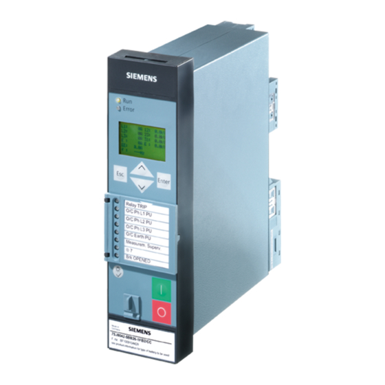
Introduction This chapter introduces the SIPROTEC 4 7SD80 and gives an overview of the device's application, properties and functions. Overall Operation Application Scope Characteristics SIPROTEC, 7SD80, Manual E50417-G1140-C474-A1, Release date 09.2011... -
Page 18: Overall Operation
1.1 Overall Operation Overall Operation The digital SIPROTEC 7SD80 overcurrent protection is equipped with a powerful microprocessor. It allows all tasks to be processed digitally, from the acquisition of measured quantities to sending commands to circuit breakers. Figure 1-1 shows the basic structure of the 7SD80 device. - Page 19 Introduction 1.1 Overall Operation There is one voltage input available for each phase-to-ground voltage. The differential protection does not need measuring voltages due to its functional principle. Directional overcurrent protection, however, requires the phase-to-ground voltage V and V to be connected. Additionally, voltages can be connected that allow displaying voltages and power values and also measuring the line voltage for automatic reclosing.
- Page 20 Introduction 1.1 Overall Operation Front Elements Information such as messages related to events, states, measured values and the functional status of the device are visualized by light-emitting diodes (LEDs) and a display screen (LCD) on the front panel. Integrated control and numeric keys in conjunction with the LCD enable communication with the remote device. These elements enable the user to retrieve all device information such as configuration and setting parameters, operational indications and fault indications or measured values and to edit setting parameters.
-
Page 21: Application Scope
Introduction 1.2 Application Scope Application Scope The digital Line Differential Protection SIPROTEC 4 7SD80 is a selective short-circuit protection for overhead lines and cables with single- and multi-ended infeeds in radial, ring or any type of meshed systems of any trans- mission level. - Page 22 Introduction 1.2 Application Scope Control Functions The device provides a control function which can be accomplished for activating and deactivating switchgear via operator buttons, port B, binary inputs and - using a PC and the DIGSI software - via the front interface. The switch positions are fed back to the device via auxiliary contacts of the circuit breakers and binary inputs.
-
Page 23: Characteristics
Introduction 1.3 Characteristics Characteristics General Properties • Powerful 32-bit microprocessor system • Complete digital processing of measured values and control, from the sampling of the analog input values, the processing and organization of the communication between devices up to the closing and tripping com- mands to the circuit breakers. - Page 24 Introduction 1.3 Characteristics External Direct and Remote Tripping • Tripping of the local end by an external device via binary input • Tripping of the opposite end by local protection functions or by an external device via binary input Time Overcurrent Protection •...
- Page 25 Introduction 1.3 Characteristics Voltage Protection • Overvoltage and undervoltage detection with different elements • Two overvoltage elements for the phase-to-ground voltages • Two overvoltage elements for the phase-to-phase voltages • Two overvoltage elements for the positive sequence voltage • Two overvoltage elements for the negative sequence system of the voltages •...
- Page 26 Introduction 1.3 Characteristics Flexible Protection Functions • Up to 20 customizable protection functions with 3-phase or 1-phase operation • Any calculated or directly measured variable can theoretically be evaluated • Standard protection logic with a constant (i.e. definite time) characteristic curve •...
-
Page 27: Functions
Functions This chapter describes the numerous functions available on the SIPROTEC 4 device 7SD80. It shows the setting possibilities for each function in maximum configuration. Information with regard to the determination of setting values as well as formulas, if required, are also provided. Based on the following information, it can also be determined which of the provided functions should be used. -
Page 28: General
Functions 2.1 General General You can edit the function parameters via the user interface or service interface from a PC running the DIGSI software; some parameters can also be changed using the controls at the front panel of the device. The pro- cedure is set out in detail in the SIPROTEC 4 System Description /1/. -
Page 29: Setting Notes
Functions 2.1 General 2.1.1.2 Setting Notes Setting the Scope of Functions Your protection device is configured using the DIGSI software. Connect your personal computer either to the USB port on the device front or to port B on the bottom side of the device depending on the device version (ordering code). - Page 30 Functions 2.1 General The AR control mode at address 134 allows a maximum of four options. On the one hand, it can be deter- mined whether the automatic reclosure cycles are carried out according to the fault type detected by the pickup of the starting protective function(s) or according to the type of trip command.
-
Page 31: Settings
Functions 2.1 General 2.1.1.3 Settings Addr. Parameter Setting Options Default Setting Comments Grp Chge OPTION Disabled Disabled Setting Group Change Option Enabled 87 DIFF.PROTEC. Enabled Enabled 87 Differential protection Disabled DTT Direct Trip Disabled Disabled DTT Direct Transfer Trip Enabled 50HS SOTF Disabled Disabled... - Page 32 Functions 2.1 General Addr. Parameter Setting Options Default Setting Comments ServiProt (CM) Disabled T103 Port B usage T103 DIGSI TIME SYNCH FLEXIBLE FCT. 1.. 20 Flexible Function 01 Please select Flexible Functions Flexible Function 02 Flexible Function 03 Flexible Function 04 Flexible Function 05 Flexible Function 06 Flexible Function 07...
-
Page 33: Device, General Settings
Functions 2.1 General 2.1.2 Device, General Settings The device requires some general information. This may be, for example, the type of annunciation to be issued in the event of an occurrence of a power system fault. 2.1.2.1 Description Command-dependent Messages "No Trip – No Flag" The indication of messages masked to local LEDs and the generation of additional messages can be made dependent on whether the device has issued a trip signal. -
Page 34: Setting Notes
Functions 2.1 General 2.1.2.2 Setting Notes Fault Display A new pickup by a protection element generally turns off any previously lit LEDs so that only the latest fault is displayed at any one time. It can be selected whether the stored LED displays and the spontaneous fault indi- cations on the display appear upon the new pickup, or only after a new trip signal is issued. -
Page 35: Information List
Functions 2.1 General 2.1.2.4 Information List Information Type of In- Comments formation Test mode IntSP Test mode DataStop IntSP Stop data transmission UnlockDT IntSP Unlock data transmission via BI Reset LED IntSP Reset LED SynchClock IntSP_Ev Clock Synchronization >Light on >Back Light on HWTestMod IntSP... - Page 36 Functions 2.1 General Information Type of In- Comments formation Error Board 2 Error Board 2 Error Board 3 Error Board 3 Error Board 4 Error Board 4 Error Board 5 Error Board 5 Error Board 0 Error Board 0 Error Offset Error: Offset Alarm adjustm.
-
Page 37: General Power System Data (Power System Data 1)
Functions 2.1 General 2.1.3 General Power System Data (Power System Data 1) The device requires certain data regarding the network and substation so that it can adapt its functions to this data depending on the application. The data required include for instance rated data of the substation and the measuring transformers, polarity and connection of the measured quantities, if necessary features of the circuit breakers, and others. - Page 38 Functions 2.1 General Current Connection The device features four current measurement inputs, three of which are connected to the set of current trans- formers. Various possibilities exist for the fourth current input I • Connection of the I input to the ground current in the neutral point of the set of current transformers on the protected feeder (normal connection, see Appendix, A.3a): Address 220 is then set to: I4 transformer = In prot.
- Page 39 Functions 2.1 General Command Duration In address 240 the minimum trip command duration TMin TRIP CMD is set. It applies to all protection and control functions that can initiate a trip command. It also determines the duration of the trip pulse when a circuit- breaker trip test is initiated via the device.
-
Page 40: Settings
Functions 2.1 General 2.1.3.2 Settings Addresses which have an appended "A" can only be changed with DIGSI, under "Display Additional Settings". Addr. Parameter Setting Options Default Setting Comments CT Starpoint towards Line towards Line CT Starpoint towards Busbar Vnom PRIMARY 0.4 .. -
Page 41: Oscillographic Fault Records
Functions 2.1 General 2.1.4 Oscillographic Fault Records The 7SD80 multifunctional protection with control is equipped with a fault record memory. The instantaneous values of the measured values and v , 3I0 , 3I0 diff rest (voltages in accordance with connection) are sampled at intervals of 1.0 ms (for 50 Hz) and stored in a revolving buffer (20 samples per cycle). -
Page 42: Settings
Functions 2.1 General 2.1.4.3 Settings Addresses which have an appended "A" can only be changed with DIGSI, under "Display Additional Settings". Addr. Parameter Setting Options Default Setting Comments 402A WAVEFORMTRIGGE Save w. Pickup Save w. Pickup Waveform Capture Save w. TRIP Start w. -
Page 43: Change Group
Functions 2.1 General 2.1.5 Change Group Up to four different setting groups can be created for establishing the device's function settings. 2.1.5.1 Description Changing Setting Groups During operation the user can switch back and forth setting groups locally, via the operator panel, binary inputs (if so configured), the service interface using a personal computer, or via the system interface. -
Page 44: Information List
Functions 2.1 General 2.1.5.4 Information List Information Type of In- Comments formation P-GrpA act IntSP Setting Group A is active P-GrpB act IntSP Setting Group B is active P-GrpC act IntSP Setting Group C is active P-GrpD act IntSP Setting Group D is active >Set Group Bit0 >Setting Group Select Bit 0 >Set Group Bit1... - Page 45 Functions 2.1 General Circuit-Breaker Status Information regarding the circuit-breaker position is required by various protection and supplementary functions to ensure their optimal functionality. The device has a circuit-breaker status recognition which processes the status of the circuit-breaker auxiliary contacts and contains also a detection based on the measured currents and voltages (see also Section 2.16).
- Page 46 Functions 2.1 General Note For CB Test and automatic reclosure the CB auxiliary contact status derived with the binary inputs >CB1 ... No. 371, 410 and 411) are relevant for the circuit-breaker test and for automatic reclosure to be able to indicate the circuit-breaker position.
-
Page 47: Settings
Functions 2.1 General 2.1.6.2 Settings Addresses which have an appended "A" can only be changed with DIGSI, under "Display Additional Settings". The table indicates region-specific default settings. Column C (configuration) indicates the corresponding sec- ondary nominal current of the current transformer. Addr. -
Page 48: Information List
Functions 2.1 General 2.1.6.3 Information List Information Type of In- Comments formation Pow.Sys.Flt. Power System fault Fault Event Fault Event >Manual Close >Manual close signal >Blk Man. Close >Block manual close cmd. from external >FAIL:Feeder VT >Failure: Feeder VT (MCB tripped) >Bkr1 Ready >Breaker 1 READY (for AR,CB-Test) >52 faulty... -
Page 49: En100-Modul 1
Functions 2.1 General 2.1.7 EN100-Module 1 2.1.7.1 Description The EN100-Module 1 enables integration of the 7SD80 in 100-Mbit communication networks in control and automation systems with the protocols according to IEC 61850 standard. This standard permits uniform com- munication of the devices without gateways and protocol converters. Even when installed in heterogeneous environments, SIPROTEC 4 relays therefore provide for open and interoperable operation. -
Page 50: Setting Notes
Functions 2.1 General Figure 2-3 Connecting 2 7SD80 devices via protection data interfaces Communication Failure The communication is continuously monitored by the devices. Single faulty data telegrams are not a direct risk if they occur only occasionally. They are recognized and counted in the device which detects the disturbance and can be read out as statistical information. -
Page 51: Settings
Functions 2.1 General 2.1.8.3 Settings Addr. Parameter Setting Options Default Setting Comments 4501 PDI FO Protection Data Interface fiber optic 4502 PDI FO TER 0.5 .. 20.0 % 1.0 % PDI FO max. telegram error rate 4503 PDI FO level -30 .. -
Page 52: Phase Comparison Protection And Ground Differential Protection
Functions 2.2 Phase Comparison Protection and Ground Differential Protection Phase Comparison Protection and Ground Differential Protection The differential protection can be used in solid or resistive grounded, isolated and resonant-grounded systems. It comprises a phase comparison protection and a ground differential protection. The sensitive ground element operates directionally or non-directionally. -
Page 53: Phase Comparison Protection
Functions 2.2 Phase Comparison Protection and Ground Differential Protection 2.2.2 Phase Comparison Protection 2.2.2.1 Description General The phase comparison protection evaluates the phase currents at both ends of the protected object. The two 7SD80 devices at the ends of the protected object communicate over their protection interfaces. The phase- specific comparison and the resulting decision to trip the circuit breaker is made separately for each end. - Page 54 Functions 2.2 Phase Comparison Protection and Ground Differential Protection Pickup Logic The dynamic and the static element pick up independently of each other selectively for each phase. To prevent tripping during an energization, a separate dynamic switch-on threshold 87L Idyn close> is used.
- Page 55 Functions 2.2 Phase Comparison Protection and Ground Differential Protection The pickup signals created locally, signs of idyn and istat and the blocking information are sent to the device at the opposite end. Figure 2-6 Phase comparison protection, sending the differential protection information to the opposite SIPROTEC, 7SD80, Manual E50417-G1140-C474-A1, Release date 09.2011...
- Page 56 Functions 2.2 Phase Comparison Protection and Ground Differential Protection The received pickup and blocking information is compared with the own differential protection information and element-specific pickup indications are created. Figure 2-7 Phase comparison protection, receiving the differential protection information from the opposite The following figure shows the formation of the phase-specific pickup of the phase comparison protection.
-
Page 57: Setting Notes
Functions 2.2 Phase Comparison Protection and Ground Differential Protection The following figure shows the pickup behavior of the phase comparison protection in resonant-grounded or isolated systems. Figure 2-9 Phase comparison protection in resonant-grounded/isolated systems You will find the logic diagram for the general pickup of the differential protection and the differential protection tripping in Section 2.2.5. - Page 58 Functions 2.2 Phase Comparison Protection and Ground Differential Protection Pickup Values for Resistive or Solid Grounded, Resonant-grounded and Isolated Systems At address 1202 87L Idyn> you can set the dynamic tripping threshold. The value for 87L Idyn> should be set to at least 0.2 of the largest primary transformer rated current and larger than 2.5 to 3 times the capacitive charging current of the line.
-
Page 59: Ground Current Differential Protection In Grounded Systems
Functions 2.2 Phase Comparison Protection and Ground Differential Protection 2.2.3 Ground Current Differential Protection in Grounded Systems The ground current differential protection of the 7SD80 operates as a stabilized (restrained) differential protec- tion in grounded systems. The two 7SD80 devices exchange the phasors of the ground currents and the asso- ciated restraining quantities over their protection interfaces. - Page 60 Functions 2.2 Phase Comparison Protection and Ground Differential Protection Evaluation of Measured Values The ground current differential protection in grounded systems evaluates the sum of the ground current pha- sors. Each device calculates a ground current at each end of the protected object (fundamental component of the ground current) and transmits it to the partner device.
- Page 61 Functions 2.2 Phase Comparison Protection and Ground Differential Protection Blocking / Interblocking The ground current differential protection can be blocked via a binary input. The blocking at one end of a pro- tected object affects all ends via the communications link (interblocking). If the overcurrent protection is config- ured as an emergency function, all devices will automatically switch to this emergency operation mode.
-
Page 62: Setting Notes
Functions 2.2 Phase Comparison Protection and Ground Differential Protection 2.2.3.2 Setting Notes General The operating mode of the ground differential protection depends on the neutral point treatment in the protected zone. In grounded systems, address 207 SystemStarpoint must be set to Grounded. The ground differential protection can be switched ON or OFF at address 1221 87N L: Protect.. -
Page 63: Ground Fault Differential Protection In Resonant-Grounded/Isolated Systems
Functions 2.2 Phase Comparison Protection and Ground Differential Protection 2.2.4 Ground Fault Differential Protection in Resonant-grounded/Isolated Systems The ground fault differential protection can be applied in power systems whose starpoint is not grounded or grounded through an arc suppression coil (Petersen coil). It is based on the power values. This requires the phase voltages or the 3V0 voltage (Appendix A.3, Figure A-11) to be connected to the devices at both ends of the protected object. - Page 64 Functions 2.2 Phase Comparison Protection and Ground Differential Protection Sensitive Ground Fault Direction Determination The direction of the ground fault can be determined from the direction of the ground fault current in relation to the displacement voltage. The only restriction is that the active or reactive current components must be avail- able with sufficient magnitude at the point of measurement.
- Page 65 Functions 2.2 Phase Comparison Protection and Ground Differential Protection Figure 2-14 Ground fault differential protection pickup, isolated/resonant-grounded system SIPROTEC, 7SD80, Manual E50417-G1140-C474-A1, Release date 09.2011...
-
Page 66: Setting Notes
Functions 2.2 Phase Comparison Protection and Ground Differential Protection If only the V0 voltage is connected, only parameter 1226 87N L: 3V0> is effective. The threshold checks 87N L:Vph-g min and 87N L:Vph-g max (parameter 1227 and 1228) are not relevant. You will find the logic diagram for the differential protection trip in Section 2.2.5. -
Page 67: Differential Protection Pickup Logic And Tripping Logic
Functions 2.2 Phase Comparison Protection and Ground Differential Protection Time Delays The ground fault is detected and reported only when the displacement voltage has applied for at least the time 87N L:TD-F.det. (address 1230). This stabilizing time also takes effect when ground fault conditions change (e.g. -
Page 68: Differential Protection
Functions 2.2 Phase Comparison Protection and Ground Differential Protection Tripping Logic The following figure shows the tripping logic of the differential protection. Figure 2-16 Differential protection trip If the pickup signals apply for longer than the configurable trip time delay, the differential protection trips. 2.2.6 87 Differential Protection The following tables provide an overview of the parameters and information of the functions:... -
Page 69: Settings
Functions 2.2 Phase Comparison Protection and Ground Differential Protection 2.2.6.1 Settings Addresses which have an appended "A" can only be changed with DIGSI, under "Display Additional Settings". The table indicates region-specific default settings. Column C (configuration) indicates the corresponding sec- ondary nominal current of the current transformer. -
Page 70: Information List
Functions 2.2 Phase Comparison Protection and Ground Differential Protection Addr. Parameter Setting Options Default Setting Comments 1235 CT Err. I2 0.003 .. 1.600 A 1.000 A Current I2 for CT Angle Error 1236 CT Err. F2 0.0 .. 5.0 ° 0.0 °... -
Page 71: Differential Protection Test And Commissioning
Functions 2.2 Phase Comparison Protection and Ground Differential Protection Information Type of In- Comments formation 32126 87N L block 87N L: Protection is blocked 32127 87N L OFF 87N L: Protection is switched off 32128 87N L 3V0> 87N L: detection 3V0> pickup 32129 87N L Forward 87N L: detection Forward... - Page 72 Functions 2.2 Phase Comparison Protection and Ground Differential Protection Depending on the way used for controlling the test mode, either the indication „Test 87 ON/off“ (no. 3199) or „Test 87 ONoffBI“ (no. 3200) is generated. The way used for deactivating the test mode always has to be identical to the way used for activating.
-
Page 73: Differential Protection Commissioning
Functions 2.2 Phase Comparison Protection and Ground Differential Protection 2.2.7.2 Differential Protection Commissioning General In differential protection commissioning mode (commissioning mode in the following) the differential protection does not generate TRIP commands. The commissioning mode is intended to support the commissioning of the differential protection. - Page 74 Functions 2.2 Phase Comparison Protection and Ground Differential Protection There are two ways to set the commissioning mode. The first way is to use a command (commissioning mode on / commissioning mode off) which is generated either when operating the integrated keypad or when oper- ating with DIGSI.
-
Page 75: Breaker Intertrip And Remote Tripping
Functions 2.3 Breaker Intertrip and Remote Tripping Breaker Intertrip and Remote Tripping The 7SD80 device allows transmitting a trip command created by the local differential protection to the other end of the protected object (intertripping). Likewise, any desired command of another internal protection func- tion or of an external protection, monitoring or control equipment can be transmitted for remote tripping. -
Page 76: Setting Notes
Functions 2.3 Breaker Intertrip and Remote Tripping Figure 2-25 Logic diagram of the intertrip — receiving circuit Additional Options Since the signals for remote tripping can be set to just generate an indication, any other desired signals can be transmitted as well. After the binary input(s) have been activated, the signals which are set to cause an alarm at the receiving end are transmitted. -
Page 77: Settings
Functions 2.3 Breaker Intertrip and Remote Tripping The setting times depend on the individual case of application. A delay is necessary if the external control signal originates from a disturbed source and a restraint seems appropriate. Of course, the control signal has to be longer than the delay for the signal to be effective. -
Page 78: Backup Overcurrent
Functions 2.4 Backup Overcurrent Backup Overcurrent The 7SD80 features an overcurrent protection function which can be used as either backup or emergency over- current protection. All elements are independent of each other and can be combined as desired. The overcurrent protection has two overcurrent elements with definite trip time and one overcurrent protection element with inverse time delay for the phase currents and for the ground current. - Page 79 Functions 2.4 Backup Overcurrent The binary input „>5X-B InstTRIP“ and the evaluation of the indication „switch“ (onto fault) are common to all elements. They may, however, separately affect the phase and/or ground current elements. Parameter 50-B1 DELAY (address 2618) determines whether a non-delayed trip of this element via binary input „>5X-B InstTRIP“...
- Page 80 Functions 2.4 Backup Overcurrent Definite Time Overcurrent Element 50-3 The 50-3 element operates independently of the other elements. Its logic corresponds to the 50-1 and 50-2 el- ements described above, but operates non-directional only. If parameter 50-STUB Inrush (address 2653) is set to YES, the element is blocked. Figure 2-27 Logic diagram of the 50-3 element Inverse Time Overcurrent Element 51...
- Page 81 Functions 2.4 Backup Overcurrent The non-directional and the directional inverse time overcurrent element 51 always uses the same character- istic curve that is parameterized via 2642 (IEC) or 2643 (ANSI). Different inverse times and additional times can be parameterized here. The following figure shows the logic diagram.
- Page 82 Functions 2.4 Backup Overcurrent Pickup Logic and Tripping Logic The pickup signals of the individual phases (or ground) and of the individual elements are interlinked in such a way that both the phase information and the element which has picked up are indicated (Table 2-1). Table 2-1 Pickup signals of the single phases Internal indication...
-
Page 83: Directional Overcurrent Protection
Functions 2.4 Backup Overcurrent 2.4.3 Directional Overcurrent Protection Measured Quantities The phase currents are fed to the device via the input transformers of the measuring input. The ground current is calculated from the phase currents. For the directional Iph> elements, the used measuring voltage is determined by the fault type. The current phase-to-ground voltage is used •... - Page 84 Functions 2.4 Backup Overcurrent Figure 2-29 Directional characteristic of the time overcurrent protection Definite Time Overcurrent Element 67-1 The directional overcurrent elements basically work in the same way as the non-directional elements. Pickup, however, depends on the result of the direction determination. The direction determination is accomplished using the measured quantities and the corresponding directional characteristics.
- Page 85 Functions 2.4 Backup Overcurrent Figure 2-30 Logic diagram of the 67-1 element SIPROTEC, 7SD80, Manual E50417-G1140-C474-A1, Release date 09.2011...
- Page 86 Functions 2.4 Backup Overcurrent Definite Time High-set Element 67-2 The directional overcurrent element basically works in the same way as the non-directional element. Pickup, however, depends on the result of the direction determination. The direction determination is accomplished using the measured quantities and the corresponding directional characteristics. 67-B1 PICKUP is used as setting values for the phase current;...
- Page 87 Functions 2.4 Backup Overcurrent Figure 2-31 Logic diagram of the 67 TOC element (directional, inverse time overcurrent protection) - example for IEC characteristic SIPROTEC, 7SD80, Manual E50417-G1140-C474-A1, Release date 09.2011...
- Page 88 Functions 2.4 Backup Overcurrent Pickup Logic and Tripping Logic The pickup signals of the individual phases (or ground) and of the individual elements are interlinked in such a way that both the phase information and the element which has picked up are indicated (Table 2-1). Table 2-2 Pickup signals of the single phases Internal indication...
-
Page 89: Setting Notes
Functions 2.4 Backup Overcurrent 2.4.4 Setting Notes General The setting notes described in the following apply to non-directional and directional overcurrent protection. Operating Modes You set the operating mode of the overcurrent protection elements specifically for each element. The setting applies collectively to the corresponding phase and ground element. - Page 90 Functions 2.4 Backup Overcurrent Inrush Blocking You can specify for each element of the overcurrent protection whether the element will be blocked when inrush is detected. The setting applies collectively to the corresponding phase and ground element. address 2625 50-1, 3I0> address 2615 50-2, 3I0>>...
- Page 91 Functions 2.4 Backup Overcurrent Time Delays The time delays are set specifically for each element: 50-B2 DELAY, 67-B2 DELAY addess 2624 50N-B2 DELAY, 67N-B2 DELAY addess 2627 50-B1 DELAY, 67-B1 DELAY addess 2614 50N-B1 DELAY, 67N-B1 DELAY addess 2617 51-B TD IEC, 67-TOC TD IEC addess 2634 (IEC characteristic) 51N-B TD IEC, 67N-TOC TD IEC addess 2639 (IEC characteristic) 51-B TD ANSI, 67-TOC TD ANSI addess 2635 (ANSI characteristic) 51N-B TD ANSI, 67N-TOC TD ANSI addess 2640 (ANSI characteristic)
- Page 92 Functions 2.4 Backup Overcurrent Characteristic Curves for the 50N Element During configuration of the scope of functions at address 126, the available characteristics were determined. Depending on the selection made there, only the parameters associated with this characteristic curve are ac- cessible.
-
Page 93: Settings
Functions 2.4 Backup Overcurrent 2.4.5 Settings Addresses which have an appended "A" can only be changed with DIGSI, under "Display Additional Settings". The table indicates region-specific default settings. Column C (configuration) indicates the corresponding sec- ondary nominal current of the current transformer. Addr. - Page 94 Functions 2.4 Backup Overcurrent Addr. Parameter Setting Options Default Setting Comments 2621 67(N)-B2 Dir. Non-Directional Non-Directional 67(N)-B2 Direction Forward Reverse 2622 67(N)-B2 on FFM Non-Directional BLOCKED 67(N)-B2 Direct. stage on BLOCKED Fuse Failure 0.10 .. 25.00 A; ∞ 2623 50-B2 PICKUP 1.50 A 50-B2 Pickup 0.50 ..
- Page 95 Functions 2.4 Backup Overcurrent Addr. Parameter Setting Options Default Setting Comments 0.50 .. 15.00 ; ∞ 2635 67-TOC TD ANSI 5.00 67-TOC Time Dial for ANSI characteristic 2636 51-B AddT-DELAY 0.00 .. 30.00 sec 5.00 sec 51-B Additional Time Delay 2636 67-TOC AddTDel.
-
Page 96: Information List
Functions 2.4 Backup Overcurrent Addr. Parameter Setting Options Default Setting Comments 2644 51(N)-B PilotBI Instantaneous trip via Pilot Prot./BI 2644 67(N)TOC Pil/BI Instantaneous trip via Pilot Prot./BI 2650 50(N)-STUB OpMo 50(N)-STUB Operating Only Emer. prot Mode 0.10 .. 25.00 A; ∞ 2651 50-STUB PICKUP 1.50 A... - Page 97 Functions 2.4 Backup Overcurrent Information Type of In- Comments formation 7162 5X-B Pickup ØA 50(N)/51(N) Backup O/C PICKUP Phase A 7163 5X-B Pickup ØB 50(N)/51(N) Backup O/C PICKUP Phase B 7164 5X-B Pickup ØC 50(N)/51(N) Backup O/C PICKUP Phase C 7165 5X-B Pickup Gnd 50(N)/51(N) Backup O/C PICKUP GROUND...
-
Page 98: Inrush Restraint
Functions 2.5 Inrush Restraint Inrush Restraint 2.5.1 Description If the protected zone of the device reaches beyond a transformer, a high inrush current must be anticipated when switching on the transformer. This current flows into the protected zone, but does not leave it again. The inrush current can amount to a multiple of the rated current and is characterized by a considerable 2nd harmonic content (double rated frequency) which is practically absent during a short circuit. -
Page 99: Setting Notes
Functions 2.5 Inrush Restraint Figure 2-33 Logic diagram of the cross-block function for one end 2.5.2 Setting Notes The inrush current detection is required for the following applications: • For the differential protection if an inductance is located in the protected zone. •... -
Page 100: Settings
Functions 2.5 Inrush Restraint 2.5.3 Settings Addr. Parameter Setting Options Default Setting Comments 2301 INRUSH REST. Inrush Restraint 2302 2nd HARMONIC 10 .. 45 % 15 % 2nd. harmonic in % of fundamen- 2303 CROSS BLOCK Cross Block 2305 MAX INRUSH PEAK 1.1 .. -
Page 101: Circuit-Breaker Failure Protection 50Bf
Functions 2.6 Circuit-Breaker Failure Protection 50BF Circuit-Breaker Failure Protection 50BF The circuit-breaker failure protection provides rapid backup fault clearance in the event that the circuit breaker fails to respond to a trip command from a protection function of the local circuit breaker. 2.6.1 Description General... - Page 102 Functions 2.6 Circuit-Breaker Failure Protection 50BF Figure 2-35 Simplified function diagram of circuit-breaker failure protection controlled by circuit-breaker auxiliary contact Monitoring the Current Flow Each of the phase currents and an additional plausibility current (see below) are filtered by numerical filter al- gorithms so that only the fundamental component is used for further evaluation.
- Page 103 Functions 2.6 Circuit-Breaker Failure Protection 50BF Figure 2-36 Current flow monitoring with plausibility currents 3·I and 3·I only usable/visible if address 139 is set to enabled w/ 3I0> SIPROTEC, 7SD80, Manual E50417-G1140-C474-A1, Release date 09.2011...
- Page 104 Functions 2.6 Circuit-Breaker Failure Protection 50BF In-Phase Start Common phase initiation is used for transformer feeders or if the busbar protection trips. If the breaker failure protection is intended to be initiated by further external protection devices, it is recom- mended, for security reasons, to connect two starting criteria to the device.
- Page 105 Functions 2.6 Circuit-Breaker Failure Protection 50BF Figure 2-38 Circuit-breaker failure protection with common phase initiation Time Delays When the initiate conditions are fulfilled, the associated timers are started. The circuit-breaker pole(s) must open before the associated time has elapsed. Time delays can be set for 3-pole initiation and for two-element protection. With single-element breaker failure protection, the trip command is relayed to the adjacent circuit breakers which interrupt the fault current if the local feeder breaker fails (see Figure 2-34 and Figure 2-35).
- Page 106 Functions 2.6 Circuit-Breaker Failure Protection 50BF Figure 2-39 Logic diagram of the two-element circuit-breaker failure protection Circuit-Breaker Malfunction There may be cases when it is already obvious that the circuit breaker associated with a feeder protection relay cannot clear a fault, e.g. when the tripping voltage or the tripping energy is not available. In such a case it is not necessary to wait for the response of the feeder circuit breaker.
- Page 107 Functions 2.6 Circuit-Breaker Failure Protection 50BF End Fault Protection An end fault is defined here as a fault which has occurred at the end of a line or protected object, between the circuit breaker and the current transformer set. This situation is shown in Figure 2-41. The fault is located — as seen from the current transformer (= measure- ment location) —...
-
Page 108: Setting Notes
Functions 2.6 Circuit-Breaker Failure Protection 50BF 2.6.2 Setting Notes General The circuit-breaker failure protection and its ancillary functions (end fault protection, pole discrepancy supervi- sion) can only operate if they were set during configuration of the scope of functions (address 139 50BF, setting Enabled or enabled w/ 3I0>). - Page 109 Functions 2.6 Circuit-Breaker Failure Protection 50BF Figure 2-43 Time sequence example for normal clearance of a fault, and with circuit-breaker failure, using two-element breaker failure protection Single-element Breaker Failure Protection In single-element breaker failure protection, the adjacent circuit breakers, i.e. the breakers of the busbar or the busbar section affected, and where applicable also the breaker at the remote end, are tripped after the time delay 50BF-2 Delay (address 3906) has elapsed.
-
Page 110: Settings
Functions 2.6 Circuit-Breaker Failure Protection 50BF Malfunction of the Local Circuit Breaker If the circuit breaker associated with the feeder is not operational (e.g. control voltage failure or air pressure failure), it is apparent that the local breaker cannot clear the fault. If the relay is informed about this disturbance (via the binary input „>52 faulty“), the adjacent circuit breakers (busbar and remote end if applicable) are tripped after the time T3-BkrDefective (address 3907) which is usually set to 0. -
Page 111: Information List
Functions 2.6 Circuit-Breaker Failure Protection 50BF Addr. Parameter Setting Options Default Setting Comments 3912 50NBF PICKUP 0.05 .. 20.00 A 0.10 A 50NBF Pickup neutral current threshold 0.25 .. 100.00 A 0.50 A 3913 T2StartCriteria With exp. of T1 Parallel withT1 T2 Start Criteria Parallel withT1 3921... -
Page 112: Thermal Overload Protection 49
Functions 2.7 Thermal Overload Protection 49 Thermal Overload Protection 49 The thermal overload protection prevents damage to the protected object caused by thermal overloading, par- ticularly in case of transformers, rotating machines, power reactors and cables. It is in general not necessary for overhead lines, since no meaningful overtemperature can be calculated because of the great variations in the environmental conditions (temperature, wind). -
Page 113: Setting Notes
Functions 2.7 Thermal Overload Protection 49 Figure 2-45 Logic diagram of the thermal overload protection 2.7.2 Setting Notes General A prerequisite for the application of the thermal overload function is that during the configuration of the func- tional scope in address 142 49 = Enabled was set. At address 4201 FCT 49 the function can be turned ON or OFF. - Page 114 Functions 2.7 Thermal Overload Protection 49 Example: Belted cable 10 kV 150 mm Permissible continuous current I = 322 A Current transformers 400 A / 5 A Setting value 49 K-FACTOR = 0.80 Time Constant The thermal time constant τ is set at address 4203 TIME CONSTANT.
-
Page 115: Settings
Functions 2.7 Thermal Overload Protection 49 Calculating the Overtemperature The thermal replica is calculated individually for each phase. Address 4206 CALC. METHOD decides whether the highest of the three calculated temperatures (Θ max) or their arithmetic average (Average Θ) or the tem- perature calculated from the phase with maximum current (Θ... -
Page 116: Undervoltage And Overvoltage Protection 27/59 (Optional)
Functions 2.8 Undervoltage and Overvoltage Protection 27/59 (Optional) Undervoltage and Overvoltage Protection 27/59 (Optional) Voltage protection has the function to protect electrical equipment against undervoltage and overvoltage. Both operational states are unfavorable as for example undervoltage may cause stability problems or overvoltage may cause insulation problems. - Page 117 Functions 2.8 Undervoltage and Overvoltage Protection 27/59 (Optional) Figure 2-46 Logic diagram of the overvoltage protection for phase voltage Overvoltage Phase-to-Phase The phase-to-phase overvoltage protection operates just like the phase-to-ground protection except that it detects phase-to-phase voltages. Accordingly, phase-to-phase voltages which have exceeded one of the element thresholds 59-1-Vpp PICKUP (address 3712) or 59-2-Vpp PICKUP (address 3714) are also indi- cated.
- Page 118 Functions 2.8 Undervoltage and Overvoltage Protection 27/59 (Optional) Overvoltage Positive Sequence System V The device calculates the positive sequence system according to its defining equation ·(V + a·V ·V j120° where a = e The resulting positive sequence voltage is fed to the two threshold elements 59-1-V1 PICKUP (address 3732) and 59-2-V1 PICKUP (address 3734) (see Figure 2-47).
- Page 119 Functions 2.8 Undervoltage and Overvoltage Protection 27/59 (Optional) Overvoltage Negative Sequence System V The device calculates the negative sequence system voltages according to its defining equation: ·(V ·V + a·V j120° where a = e The resulting negative sequence voltage is fed to the two threshold elements 59-1-V2 PICKUP (address 3742) and 59-2-V2 PICKUP (address 3744).
- Page 120 Functions 2.8 Undervoltage and Overvoltage Protection 27/59 (Optional) Overvoltage Zero Sequence System 3V Figure 2-49 depicts the logic diagram of the zero sequence voltage element. The fundamental frequency is nu- merically filtered from the measuring voltage so that the harmonics or transient voltage peaks remain largely harmless.
-
Page 121: Undervoltage Protection (Ansi 27)
Functions 2.8 Undervoltage and Overvoltage Protection 27/59 (Optional) 2.8.2 Undervoltage Protection (ANSI 27) Undervoltage Phase–Ground Figure 2-50 depicts the logic diagram of the phase voltage elements. The fundamental frequency is numerically filtered from each of the three measuring voltages so that harmonics or transient voltage peaks are largely harmless. - Page 122 Functions 2.8 Undervoltage and Overvoltage Protection 27/59 (Optional) Figure 2-50 Logic diagram of the undervoltage protection for phase voltages SIPROTEC, 7SD80, Manual E50417-G1140-C474-A1, Release date 09.2011...
- Page 123 Functions 2.8 Undervoltage and Overvoltage Protection 27/59 (Optional) Undervoltage Phase-to-Phase Basically, the phase-to-phase undervoltage protection operates like the phase-to-ground protection except that it detects phase-to-phase voltages. Accordingly, both phases are indicated during pickup of an undervoltage element if one of the stage thresholds 27-1-Vpp PICKUP (address 3762) or 27-2-Vpp PICKUP (address 3764) was undershot.
-
Page 124: Setting Notes
Functions 2.8 Undervoltage and Overvoltage Protection 27/59 (Optional) Figure 2-51 Logic diagram of the undervoltage protection for positive sequence voltage system 2.8.3 Setting Notes General The voltage protection can only operate if it has been set to Enabled during the configuration of the device scope (address 137). - Page 125 Functions 2.8 Undervoltage and Overvoltage Protection 27/59 (Optional) Overvoltage Phase-to-Ground The phase voltage elements can be switched ON or OFF in address 3701 59-Vph-g Mode. In addition to this, you can set Alarm Only, i.e. these elements operate and send alarms but do not generate any trip command. The setting V>Alarm V>>Trip creates in addition also a trip command only for the 59-2 element (V>>).
- Page 126 Functions 2.8 Undervoltage and Overvoltage Protection 27/59 (Optional) This protective function also has two elements, one being 59-1-V2 PICKUP (address 3742) with a greater time delay 59-1-V2 DELAY (address 3743) for steady-state asymmetrical voltages and the other being 59- 2-V2 PICKUP (address 3744) with a short time delay 59-2-V2 DELAY (address 3745) for high asymmetrical voltages.
-
Page 127
Functions 2.8 Undervoltage and Overvoltage Protection 27/59 (Optional) Undervoltage Phase-to-Phase Basically, the same considerations apply as for the phase undervoltage elements. These elements may replace the phase voltage elements or be used additionally. Accordingly set address 3761 27-Vph-ph Mode to ON, OFF, Alarm Only or V
Page 128: Settings
Functions 2.8 Undervoltage and Overvoltage Protection 27/59 (Optional) 2.8.4 Settings Addresses which have an appended "A" can only be changed with DIGSI, under "Display Additional Settings". Addr. Parameter Setting Options Default Setting Comments 3701 59-Vph-g Mode Operating mode Vph-g overvolt- Alarm Only age prot.- Page 129 Functions 2.8 Undervoltage and Overvoltage Protection 27/59 (Optional) Addr. Parameter Setting Options Default Setting Comments 0.00 .. 100.00 sec; ∞ 3735 59-2-V1 DELAY 1.00 sec 59-2 Time Delay 3739A 59-V1 RESET 0.30 .. 0.99 0.98 Reset ratio 3741 59-V2 Mode Operating mode V2 overvoltage Alarm Only prot.
Page 130: Information List
Functions 2.8 Undervoltage and Overvoltage Protection 27/59 (Optional) Addr. Parameter Setting Options Default Setting Comments 0.00 .. 100.00 sec; ∞ 3773 27-1-V1 DELAY 2.00 sec 27-1 Time Delay 3774 27-2-V1 PICKUP 1.0 .. 100.0 V; 0 10.0 V 27-2 Pickup Undervoltage (pos. seq.) 0.00 ..- Page 131 Functions 2.8 Undervoltage and Overvoltage Protection 27/59 (Optional) Information Type of In- Comments formation 10247 59-Vpg TRIP 59-Vphg TRIP command 10248 59-1-Vpg PU A 59-1-Vphg Pickup A 10249 59-1-Vpg PU B 59-1-Vphg Pickup B 10250 59-1-Vpg PU C 59-1-Vphg Pickup C 10251 59-2-Vpg PU A 59-2-Vphg Pickup A...
- Page 132 Functions 2.8 Undervoltage and Overvoltage Protection 27/59 (Optional) Information Type of In- Comments formation 10315 27-1-VpgTimeOut 27-1-Vphg TimeOut 10316 27-2-VpgTimeOut 27-2-Vphg TimeOut 10317 27-Vpg TRIP 27-Vphg TRIP command 10318 27-1-Vpg PU A 27-1-Vphg Pickup A 10319 27-1-Vpg PU B 27-1-Vphg Pickup B 10320 27-1-Vpg PU C 27-1-Vphg Pickup C...
Page 133: Frequency Protection 81 (Optional)
Functions 2.9 Frequency Protection 81 (Optional) Frequency Protection 81 (Optional) The frequency protection function detects abnormally high and low frequencies in the system or in electrical machines. If the frequency lies outside the allowable range, appropriate actions are initiated, such as load shedding or separating a generator from the system.- Page 134 Functions 2.9 Frequency Protection 81 (Optional) Operating Ranges Frequency evaluation requires a measured quantity that can be processed. This implies that at least a suffi- ciently high voltage is available and that the frequency of this voltage is within the working range of the frequen- cy protection.
- Page 135 Functions 2.9 Frequency Protection 81 (Optional) Figure 2-52 Logic diagram of frequency protection for 50 Hz rated frequency SIPROTEC, 7SD80, Manual E50417-G1140-C474-A1, Release date 09.2011...
Page 136: Setting Notes
Functions 2.9 Frequency Protection 81 (Optional) 2.9.2 Setting Notes General Frequency protection is only in effect and accessible if address 136 81 O/U is set to Enabled during config- uration of protective functions. If the function is not required, set Disabled. The frequency protection function features 4 frequency elements f1 to f4 each of which can function as over- frequency element or underfrequency element.Page 137: Settings
Functions 2.9 Frequency Protection 81 (Optional) • Address 3622 81-3 PICKUP pickup value for frequency element f3 at f = 50 Hz, Address 3623 81-3 PICKUP pickup value for frequency element f3 at f = 60 Hz, Address 3624 81-3 DELAY trip delay for frequency element f3; •...Page 138: Information List
Functions 2.9 Frequency Protection 81 (Optional) Addr. Parameter Setting Options Default Setting Comments 3622 81-3 PICKUP 45.50 .. 54.50 Hz 47.50 Hz 81-3 Pickup 3623 81-3 PICKUP 55.50 .. 64.50 Hz 59.50 Hz 81-3 Pickup 3624 81-3 DELAY 0.00 .. 600.00 sec 3.00 sec 81-3 Time delay 3631...Page 139: Direct Local Trip
Functions 2.10 Direct Local Trip 2.10 Direct Local Trip Any signal from an external protection or monitoring device can be coupled into the signal processing of the 7SD80 by means of a binary input. This signal may be delayed, alarmed and routed to one or several output relays.Page 140: Setting Notes
Functions 2.10 Direct Local Trip 2.10.2 Setting Notes General In order to use the direct and remote tripping functions, address 122 DTT Direct Trip must have been set to Enabled during the configuration of the device functional scope. At address 2201 Direct Trip(DT) it can also be switched ON or OFF.Page 141: Automatic Reclosure Function 79 (Optional)
Functions 2.11 Automatic Reclosure Function 79 (Optional) 2.11 Automatic Reclosure Function 79 (Optional) Experience shows that about 85% of the arc faults on overhead lines are extinguished automatically after being tripped by the protection. This means that the line can be connected again. Reclosing is performed by an au- tomatic reclosing function (AR).- Page 142 Functions 2.11 Automatic Reclosure Function 79 (Optional) Initiation Initiation of the automatic reclosing function means storing the first trip signal of a power system fault that was generated by a protection function which operates with the automatic reclosing function, e.g. phase comparison protection or ground fault differential protection.
- Page 143 Functions 2.11 Automatic Reclosure Function 79 (Optional) Blocking the Reclosing Function Different conditions lead to blocking of the automatic reclosing function. No reclosing is possible, for example, if it is blocked via a binary input. If the automatic reclosing function has not been started yet, it cannot be started at all.
- Page 144 Functions 2.11 Automatic Reclosure Function 79 (Optional) Processing the Auxiliary Contacts of the Circuit Breaker If the circuit-breaker auxiliary contacts are connected to the device, the reaction of the circuit breaker is also checked for plausibility. If the series connections of the normally open and normally closed contacts of the poles are connected, the circuit breaker is assumed to have all three poles open when the series connection of the normally closed con- tacts is closed (binary input „>52b Bkr1 3p Op“, no.411).
- Page 145 Functions 2.11 Automatic Reclosure Function 79 (Optional) Handling of Evolving Faults If reclose cycles are executed in the power system, particular attention must be paid to evolving faults. Sequential faults are faults which occur during the dead time after clearance of the first fault. To detect an evolving fault, you can select either the trip command of a protection function during the dead time or every further pickup as the criterion for an evolving fault.
- Page 146 Functions 2.11 Automatic Reclosure Function 79 (Optional) Control of the Internal Automatic Reclosure by an External Protection Device The internal automatic reclosure function of the device can be controlled by an external protection device. This is of use, for example, on line ends with redundant protection or additional backup protection when the second protection is used for the same line end and has to work with the automatic reclosing function integrated in the 7SD80.
- Page 147 Functions 2.11 Automatic Reclosure Function 79 (Optional) Figure 2-57 Connection example with external protection device for fault detection dependent dead time — dead time control by pickup signals of the protection device; AR control mode = with PICKUP SIPROTEC, 7SD80, Manual E50417-G1140-C474-A1, Release date 09.2011...
Page 148: Setting Notes
Functions 2.11 Automatic Reclosure Function 79 (Optional) 2.11.2 Setting Notes If the automatic reclosing function is not required, it can be set to Disabled at address 133. All parameters for the settings of the automatic reclosing function are thus not accessible. To use the internal automatic reclosing function, the type of reclosing must be specified at address 133 79 Auto Recl.- Page 149 Functions 2.11 Automatic Reclosure Function 79 (Optional) The options for handling evolving faults are described in Section 2.11 under margin heading „Handling Evolving Faults“. You can define recognition of an evolving fault at address 3406 EV. FLT. RECOG.. EV. FLT. RECOG.with PICKUP means that during a dead time each pickup of a protection function will be interpreted as an evolving fault.
- Page 150 Functions 2.11 Automatic Reclosure Function 79 (Optional) The action time 1.AR:ActionTime (address 3451) is the time after initiation (fault detection) by any protec- tive function which can start the automatic reclosure function within which the trip command must appear. If the command does not appear until after the action time has expired, there is no reclosure.
- Page 151 Functions 2.11 Automatic Reclosure Function 79 (Optional) Notes on the Information Overview The most important information about automatic reclosure is briefly explained insofar as it was not mentioned in the following lists or described in detail in the preceding text. „>BLK 1.AR-cycle“...
Page 152: Settings
Functions 2.11 Automatic Reclosure Function 79 (Optional) 2.11.3 Settings Addresses which have an appended "A" can only be changed with DIGSI, under "Display Additional Settings". Addr. Parameter Setting Options Default Setting Comments 3401 FCT 79 79 Auto-Reclose Function 3402 52? 1.TRIP 52-ready interrogation at 1st trip 3403 T-RECLAIM...- Page 153 Functions 2.11 Automatic Reclosure Function 79 (Optional) Addr. Parameter Setting Options Default Setting Comments 0.01 .. 1800.00 sec; ∞ 3465 2.AR:DeadT.2Flt 1.20 sec Dead time after 2phase faults 0.01 .. 1800.00 sec; ∞ 3466 2.AR:DeadT.3Flt 0.50 sec Dead time after 3phase faults 0.01 ..
Page 154: Information List
Functions 2.11 Automatic Reclosure Function 79 (Optional) 2.11.4 Information List Information Type of In- Comments formation 79 ON/OFF IntSP 79 ON/OFF (via system port) 2701 >79 ON >79 ON 2702 >79 OFF >79 OFF 2703 >BLOCK 79 >BLOCK 79 2711 >79 Start >79 External start of internal A/R 2716...Page 155: Circuit-Breaker Test
Functions 2.12 Circuit-Breaker Test 2.12 Circuit-Breaker Test 2.12.1 CB Close Detection During energization of the protected object, several measures may be required or desirable. Following a manual closure onto a short circuit, immediate trip of the circuit breaker is usually desired. This is done, e.g. in the overcurrent protection by bypassing the time delay of a current element.- Page 156 Functions 2.12 Circuit-Breaker Test Figure 2-59 Manual closure with internal automatic reclosure Circuit breaker 52TC Circuit-breaker trip coil 52 Aux Auxiliary contact of the circuit breaker If, however, external close commands are possible which are not supposed to activate the manual close func- tion (e.g.
- Page 157 Functions 2.12 Circuit-Breaker Test The phase currents and the phase-to-ground voltages are available as measuring quantities. A flowing current excludes that the circuit breaker is open (exception: a short-circuit between current transformer and circuit breaker). If the circuit breaker is closed, it may, however, still occur that no current is flowing. The voltages can only be used as a criterion for the de-energized line if the voltage transformers are installed on the feeder side.
Page 158: Circuit-Breaker Position Detection
Functions 2.12 Circuit-Breaker Test 2.12.2 Circuit-Breaker Position Detection For Protection Purposes Different protection and supplementary functions need information about the circuit-breaker status in order to operate optimally. This is helpful for • the circuit-breaker failure protection (refer to Section 2.6), •...Page 159: Circuit-Breaker Test
Functions 2.12 Circuit-Breaker Test For Automatic Reclosing and Circuit-Breaker Test Separate binary inputs comprising information on the position of the circuit breaker are available for the auto- matic reclosing function and the circuit-breaker test. This is important for • the plausibility check before automatic reclosing (refer to Section 2.11), •...Page 160: Information List
Functions 2.12 Circuit-Breaker Test 2.12.4 Information List Information Type of In- Comments formation CB1tst ABC CB1-TEST trip/close Phases ABC 7328 CB1-TESTtripABC CB1-TEST TRIP command ABC 7329 CB1-TEST close CB1-TEST CLOSE command 7345 CB-TEST running CB-TEST is in progress 7346 CB-TSTstop FLT. OUT_Ev CB-TEST canceled due to Power Sys.Page 161: Direct Remote Trip And Transmission Of Binary Information
Functions 2.13 Direct Remote Trip and Transmission of Binary Information 2.13 Direct Remote Trip and Transmission of Binary Information 2.13.1 Description 7SD80 allows up to 16 information items of any type to be transmitted from one device to another. Like the protection signals, these are transmitted with high priority.Page 162: Information List
Functions 2.13 Direct Remote Trip and Transmission of Binary Information 2.13.2 Information List Information Type of In- Comments formation 3549 >Rem. Signal 1 >Remote Signal 1 input 3550 >Rem.Signal 2 >Remote Signal 2 input 3551 >Rem.Signal 3 >Remote Signal 3 input 3552 >Rem.Signal 4 >Remote Signal 4 input...Page 163: Monitoring Functions
Functions 2.14 Monitoring Functions 2.14 Monitoring Functions The device features comprehensive monitoring functions for both the hardware and the software. The measur- ing circuits are continuously checked for plausibility. Monitoring thus covers current transformers and voltage transformers to a large extent. Trip circuit supervision can be implemented using the available binary inputs. 2.14.1 Measurement Supervision 2.14.1.1 Hardware Monitoring...- Page 164 Functions 2.14 Monitoring Functions Measured-Value Acquisition – Currents Up to four input currents are measured by the device. If the three phase currents and the ground fault current from the current transformer neutral or a separated ground current transformer of the line to be protected are connected to the device, their digitized sum must be zero.
Page 165: Software Monitoring
Functions 2.14 Monitoring Functions 2.14.1.2 Software Monitoring Watchdog For continuous monitoring of the program sequences, a time monitor is provided in the hardware (hardware watchdog) that expires upon failure of the processor or an internal program, and causes a complete restart of the processor system.- Page 166 Functions 2.14 Monitoring Functions Figure 2-65 Current symmetry monitoring Voltage Balance During healthy system operation, a certain balance of the voltages can be assumed. The monitoring of the measured values in the device checks this balance. The smallest phase-to-phase voltage is compared to the largest.
- Page 167 Functions 2.14 Monitoring Functions Wire Break Monitoring During steady-state operation the broken wire monitoring detects interruptions in the secondary circuit of the current transformers. In addition to the hazardous potential caused by high voltages in the secondary circuit, this kind of interruptions simulate differential currents to the differential protection, such as those evoked by faults in the protected object.
- Page 168 Functions 2.14 Monitoring Functions A wire break is signaled under the following conditions: • A suspected local wire break has been detected. • The logic for detecting the circuit-breaker position (see Section 2.16, Detection of the Circuit-Breaker Posi- tion) does not signal an open circuit-breaker pole. Broken wire detection is not possible if the circuit breaker is open.
- Page 169 Functions 2.14 Monitoring Functions Figure 2-68 Broken-wire monitoring Voltage Phase Rotation Phase rotation of measured voltages is checked by verifying the phase sequences of the voltages leads V leads V This check takes place if each measured voltage has a minimum magnitude of |, |V |, |V | >...
- Page 170 Functions 2.14 Monitoring Functions Figure 2-69 and 2-70 show the logic of the „fuse-failure monitor“. Figure 2-69 Fuse Failure Monitor part 1: detection of the asymmetrical measuring voltage failure Unbalanced measuring voltage failure is characterized by voltage unbalance with simultaneous current bal- ance.
- Page 171 Functions 2.14 Monitoring Functions If a zero sequence or negative sequence current occurs within 10 s after detecting the unbalanced measuring voltage failure, a short circuit is assumed to exist in the system and the signal „VT FuseFail“ is canceled immediately.
- Page 172 Functions 2.14 Monitoring Functions If such a voltage failure is recognized, the protection functions that operate on the basis of undervoltage are blocked until the voltage failure is removed; afterwards the blocking is automatically removed. The definite time overcurrent protection as emergency function is possible during voltage failure, provided that the time overcur- rent protection is parameterized accordingly (refer to Section 2.4).
- Page 173 Functions 2.14 Monitoring Functions Logic diagram of the additional measuring-voltage failure detection „Fail V absent“ Figure 2-71 Impact of the Measuring Voltage Failure In the event of a measuring voltage failure due to a short circuit or a broken conductor in the voltage transformer secondary circuit, individual or all measuring loops may mistakenly see a voltage of zero.
Page 174: Fault Responses
Functions 2.14 Monitoring Functions Figure 2-72 Impact of the measuring voltage failure 2.14.1.4 Fault Responses Depending on the type of fault detected, an alarm is output, the processor system is restarted or the device is taken out of operation. After three unsuccessful restart attempts, the device is also shut down. The device ready relay drops out and indicates the device failure with its NC contact („life status contact“).- Page 175 Functions 2.14 Monitoring Functions Table 2-4 Summary of the Device's Fault Responses Monitoring Possible causes Fault response Indication (no.) Output Auxiliary voltage External (aux. voltage) Inter- Device out of operation All LEDs dark drops out failure nal (converter) Measured-value ac- Internal (converter or refer- Protection out of opera- ERROR „LED“...
Page 176: Setting Notes
Functions 2.14 Monitoring Functions 2.14.1.5 Setting Notes General The sensitivity of measured value monitoring can be modified. Default values which are sufficient in most cases are preset. If especially high operational asymmetries of the currents and/or voltages are anticipated during operation, or if it becomes apparent during operation that certain monitoring functions pick up sporadically, then the setting should be less sensitive.Page 177: Settings
Functions 2.14 Monitoring Functions 3-Phase Measuring Voltage Failure "Fuse Failure Monitor" The minimum voltage below which a 3-phase measured voltage failure is detected is set in address 2913 FFM VPage 178: Information List
Functions 2.14 Monitoring Functions Addr. Parameter Setting Options Default Setting Comments 2914A FFM Idiff (3ph) 0.05 .. 1.00 A 0.10 A Differential Current Threshold (3phase) 0.25 .. 5.00 A 0.50 A 2915 V-Supervision w/ CURR.SUP w/ CURR.SUP Voltage Failure Supervi- w/ I>...Page 179: 74Tc Trip Circuit Supervision
Functions 2.14 Monitoring Functions 2.14.2 74TC Trip Circuit Supervision The 7SD80 line protection is equipped with an integrated trip circuit supervision function. Depending on the number of available binary inputs (not connected to a common potential), supervision with one or two binary inputs can be selected.- Page 180 Functions 2.14 Monitoring Functions Monitoring with two binary inputs does not only detect interruptions in the trip circuit and loss of control voltage, it also monitors the response of the circuit breaker using the position of the circuit-breaker auxiliary contacts. Depending on the conditions of the trip contact and the circuit breaker, the binary inputs are activated (logical condition „H“...
- Page 181 Functions 2.14 Monitoring Functions Figure 2-75 Principle of the trip circuit monitoring with one binary input Relay trip contact Circuit breaker 52TC Circuit-breaker trip coil Circuit-breaker auxiliary contact (NO contact) Circuit-breaker auxiliary contact (NC contact) V-CTRL Control Voltage for trip circuit V-BI Input voltage for binary input Bypass resistor...
Page 182: Setting Notes
Functions 2.14 Monitoring Functions 2.14.2.2 Setting Notes General The number of circuits to be monitored was set during the configuration in address 140 74 Trip Ct Supv (Section 2.1.1.2). If the trip circuit supervision is not used at all, the setting Disabled must be applied there. The trip circuit supervision can be switched ON or OFF in address 4001 FCT 74TC.Page 183: Flexible Protection Functions
Functions 2.15 Flexible Protection Functions 2.15 Flexible Protection Functions The flexible protection function is applicable for a variety of protection principles. The user can create up to 20 flexible protection functions and configure them according to their function. Each function can be used either as an autonomous protection function, as an additional protective element of an existing protection function or as a universal logic, e.g.- Page 184 Functions 2.15 Flexible Protection Functions The maximum 20 configurable protection functions operate independently of each other. The following descrip- tion concerns one function; it can be applied accordingly to all other flexible functions. The logic diagram 2-77 illustrates the description. Functional Logic The function can be switched ON and OFF or, it can be set to Alarm Only.
- Page 185 Functions 2.15 Flexible Protection Functions Figure 2-77 Logic diagram of the flexible protection functions The parameters can be set to monitor either exceeding or dropping below of the threshold. The configurable pickup time delay will be started once the threshold (>-Element) has been exceeded. When the time delay has elapsed and the threshold is still violated, the pickup of the phase (e.g.
- Page 186 Functions 2.15 Flexible Protection Functions binary input has been activated. The trip command can be blocked via binary inputs (no. 235.2115 „>$00 BL.TripA“) and (no. 235.2114 „>$00 BLK.TRIP“). The phase-selective blocking of the trip command is required for interaction with the inrush restraint (see „Interaction with other functions“). The function's dropout ratio can be set.
Page 187: Setting Notes
Functions 2.15 Flexible Protection Functions 2.15.2 Setting Notes The setting of the functional scope determines the number of flexible protection functions to be used (see Chapter 2.1.1). If a flexible function in the functional scope is disabled (by removing the checkmark), this will result in losing all settings and configurations of this function or its settings will be reset to their default settings.- Page 188 Functions 2.15 Flexible Protection Functions Table 2-8 Parameter in the "Measurement Method" settings dialog, 3-phase operation Operating Measurand Notes Method 3-phase Current, Parameter MEAS. voltage METHOD Setting selection Fundamental component The fundamental component is evaluated, harmonics are sup- pressed. This is the standard measurement method of the pro- tection functions.
- Page 189 Functions 2.15 Flexible Protection Functions Table 2-9 Parameter in the "Measurement Method" settings dialog, 1-phase operation Operating Measurand Notes Method 1-phase Current, Parameter MEAS. voltage METHOD Setting selection Fundamental component The fundamental component is evaluated, harmonics are sup- pressed. This is the standard measurement method of the pro- tection functions.
- Page 190 Functions 2.15 Flexible Protection Functions When setting the power threshold values, it is important to take into consideration that a minimum current of 0.03 I is required for power calculation. The power calculation is blocked for lower currents. The dropout of pickup can be delayed via parameter T DROPOUT DELAY. This setting is also set to zero by default (standard setting) A setting deviating from zero may be required if the device is utilized together with electro-magnetic devices with considerably longer dropout ratios than the digital protection device (see Chapter 2.2 for more information).
Page 191: Settings
Functions 2.15 Flexible Protection Functions 2.15.3 Settings Addresses which have an appended "A" can only be changed with DIGSI, under "Display Additional Settings". The table indicates region-specific default settings. Column C (configuration) indicates the corresponding sec- ondary nominal current of the current transformer. Addr.- Page 192 Functions 2.15 Flexible Protection Functions Addr. Parameter Setting Options Default Setting Comments P.U. THRESHOLD 0.03 .. 40.00 A 2.00 A Pickup Threshold 0.15 .. 200.00 A 10.00 A P.U. THRESHOLD 0.001 .. 1.500 A 0.100 A Pickup Threshold P.U. THRESHOLD 2.0 ..
Page 193: Information List
Functions 2.15 Flexible Protection Functions 2.15.4 Information List Information Type of In- Comments formation 235.2110 >BLOCK $00 >BLOCK Function $00 235.2111 >$00 instant. >Function $00 instantaneous TRIP 235.2112 >$00 Dir.TRIP >Function $00 Direct TRIP 235.2113 >$00 BLK.TDly >Function $00 BLOCK TRIP Time Delay 235.2114 >$00 BLK.TRIP >Function $00 BLOCK TRIP 235.2115 >$00 BL.TripA...Page 194: Function Control
Functions 2.16 Function Control 2.16 Function Control 2.16.1 Pickup Logic for the Entire Device Phase Segregated Fault Detection The fault detection logic combines the fault detection (pickup) signals of all protection functions. The protection functions that allow phase segregated pickup the output is done in a phase segregated manner. If a protection function detects a ground fault, this is also output as a common device alarm.Page 195: Overall Tripping Logic Of The Device
Functions 2.16 Function Control 2.16.2 Overall Tripping Logic of the Device 3-Pole Tripping The device trips 3-pole in the event of a fault. The output function „Relay TRIP“ is used for to send the command to the circuit breaker. General Trip All trip signals for the protection functions are connected by OR and generate the indication „Relay TRIP“.- Page 196 Functions 2.16 Function Control Reclosure Interlocking After the circuit breaker has been tripped by a protection function, the reclosing must often be blocked until the cause for tripping of the protection function has been found. 7SD80 enables this via the integrated reclosure interlocking.
- Page 197 Functions 2.16 Function Control Breaker Tripping Alarm Suppression While every trip command by a protection function is final on a feeder without automatic reclosure, it is desir- able, when using automatic reclosure, to prevent the operation detector of the circuit breaker (transient contact on the breaker) from sending an alarm if the trip of the breaker is not final (Figure 2-80).
- Page 198 Functions 2.16 Function Control Figure 2-81 shows time diagrams for manual trip and close as well as for short-circuit tripping with a single, failed automatic reclosure cycle. Figure 2-81 Breaker tripping alarm suppression — sequence examples SIPROTEC, 7SD80, Manual E50417-G1140-C474-A1, Release date 09.2011...
Page 199: Additional Functions
Functions 2.17 Additional Functions 2.17 Additional Functions 2.17.1 Indications Processing After the occurrence of a system fault, information regarding the response of the protective relay and the mea- sured values is important for a detailed analysis. An information processing function in the device takes care of this.Page 200: Information Via Display Field Or Pc
Functions 2.17 Additional Functions 2.17.1.2 Information via Display Field or PC Using the front PC interface or the port B at the bottom, a personal computer can be connected, to which the information can be sent. The relay is equipped with several event buffers for operational messages, circuit-breaker statistics, etc., which are protected against loss of the auxiliary voltage by a buffer battery.Page 201: Information To A Control Center
Functions 2.17 Additional Functions Retrievable Messages The messages for the last eight network faults can be retrieved and read out. The definition of a network fault is such that the time period from fault detection up to final clearing of the disturbance is considered to be one network fault.Page 202: Description
Functions 2.17 Additional Functions 2.17.2.1 Description Counters and Memories The counters and memories of the statistics are saved by the device. Therefore, the information will not get lost in case the auxiliary voltage supply fails. The counters, however, can be reset to zero or to any value within the setting range.Page 203: Measurement During Operation
Functions 2.17 Additional Functions 2.17.3 Measurement During Operation 2.17.3.1 Description A series of measured values and the values derived from them are available for on-site retrieval or for data transfer. A precondition for a correct display of primary and percentage values is the complete and correct entry of the rated values of the instrument transformers and the power system as well as the transformation ratio of the current and voltage transformers in the ground paths.- Page 204 Functions 2.17 Additional Functions Table 2-10 Operational measured values of the local device Measured Values Primary Second- % referred to Phase currents Rated operational current Ground current Rated operational current ϕ(I ), ϕ(I ), ϕ(I Phase angle of the phase currents °...
Page 205: Information List
Functions 2.17 Additional Functions 2.17.3.2 Information List Information Type of In- Comments formation Ia = Ib = Ic = 3I0 = 3I0 (zero sequence) 3I0sen= 3I0sen (sensitive zero sequence) Ig = Ig (grounded transformer) 3I0par= 3I0par (parallel line neutral) I1 (positive sequence) I2 (negative sequence) Va = Vb =...Page 206: Differential Protection Values
Functions 2.17 Additional Functions 2.17.4 Differential Protection Values 2.17.4.1 Measured Values of the Differential Protection The differential and restraint current values of the differential protection can be displayed at the front of the device, read out via the operating interface using a PC with DIGSI, or transferred to a control center via the system interface.Page 207: Min/Max Measurement Setup
Functions 2.17 Additional Functions Table 2-12 Measured values constellation for device 1 Information Type of In- Comments formation 7761 „Relay ID“ Device address of the device 7762 „I A_opN=“ IA (% of nominal operational current) 7763 „ΦI A=“ Angle IA_remote <-> IA_local 7764 „I B_opN=“...Page 208: Settings
Functions 2.17 Additional Functions 2.17.6.3 Settings Addr. Parameter Setting Options Default Setting Comments 2811 MinMax cycRESET Automatic Cyclic Reset Function 2812 MiMa RESET TIME 0 .. 1439 min 0 min MinMax Reset Timer 2813 MiMa RESETCYCLE 1 .. 365 Days 7 Days MinMax Reset Cycle Period 2814...- Page 209 Functions 2.17 Additional Functions Information Type of In- Comments formation Ic Min= Ic Min Ic Max= Ic Max I1 Min= I1 (positive sequence) Minimum I1 Max= I1 (positive sequence) Maximum Va-nMin= Va-n Min Va-nMax= Va-n Max Vb-nMin= Vb-n Min Vb-nMax= Vb-n Max Vc-nMin= Vc-n Min...
Page 210: Demand Measurement Setup
Functions 2.17 Additional Functions 2.17.7 Demand Measurement Setup The long-term averages are calculated and output by the 7SD80. 2.17.7.1 Description Long-Term Averages The long-term averages of the three phase currents I , the positive sequence components I for the three phase currents, and the real power P, reactive power Q, and apparent power S are calculated within a set period of time and indicated in primary values.Page 211: Information List
Functions 2.17 Additional Functions 2.17.7.4 Information List Information Type of In- Comments formation I1 dmd= I1 (positive sequence) Demand P dmd = Active Power Demand Q dmd = Reactive Power Demand S dmd = Apparent Power Demand Ia dmd= I A demand Ib dmd= I B demand Ic dmd=...Page 212: Set Points (Measured Values)
Functions 2.17 Additional Functions 2.17.8 Set Points (Measured Values) 2.17.8.1 Setting Notes Setpoints for Measured Values Setting is performed in the DIGSI configuration Matrix under Settings, Masking I/O (Configuration Matrix). Apply the filter "Measured and Metered Values Only" and select the configuration group "Set Points (MV)". Here you can insert new limit values via the Information Catalog which are subsequently linked to the mea- sured value to be monitored using CFC.Page 213: Energy
Functions 2.17 Additional Functions 2.17.9 Energy Metered values for real and reactive power are determined by the processor system in the background. They can be called up at the front of the device, read out via the operating interface using a PC with DIGSI, or trans- ferred to a central master station via the system interface.Page 214: Breaker Control
Functions 2.18 Breaker Control 2.18 Breaker Control A control command process is integrated in the SIPROTEC 4 device 7SD80 to coordinate the operation of circuit breakers and other equipment in the power system. Control commands can originate from four command sources: •...Page 215: Information List
Functions 2.18 Breaker Control Operation Using the System Interface Switchgear can be controlled via the serial system interface and a connection to the substation control equip- ment. For that it is necessary that the required periphery is physically existing in the device as well as in the substation.Page 216: Command Types
Functions 2.18 Breaker Control 2.18.2 Command Types In conjunction with the power system control several command types can be distinguished for the device: 2.18.2.1 Description Commands to the Process These are all commands that are directly output to the switchgear to change their process state: •...Page 217: Command Sequence
Functions 2.18 Breaker Control 2.18.3 Command Sequence Safety mechanisms in the command sequence ensure that a command can only be released after a thorough check of preset criteria has been successfully concluded. Standard Interlocking checks are provided for each individual control command. Additionally, user-defined interlocking conditions can be programmed separately for each command.Page 218: Switchgear Interlocking Protection
Functions 2.18 Breaker Control 2.18.4 Switchgear Interlocking Protection System interlocking is executed by the user-defined logic (CFC). 2.18.4.1 Description Interlocking checks in a SICAM/SIPROTEC 4 system are normally divided in the following groups: • System interlocking relies on the system data base in the substation or central control system. •...- Page 219 Functions 2.18 Breaker Control The check of interlocking can be programmed separately for all switching devices and tags that were set with a tagging command. Other internal commands such as manual entry or abort are not checked, i.e. carried out independent of the interlocking.
- Page 220 Functions 2.18 Breaker Control Figure 2-84 Standard interlockings SIPROTEC, 7SD80, Manual E50417-G1140-C474-A1, Release date 09.2011...
- Page 221 Functions 2.18 Breaker Control The following figure shows the configuration of the interlocking conditions using DIGSI. Figure 2-85 DIGSI dialog box for setting the interlocking conditions On devices with operator panel, the display shows the configured interlocking reasons. They are marked with letters explained in the following table.
- Page 222 Functions 2.18 Breaker Control Standard Interlocking (default) The standard interlockings contain the following fixed programmed tests for each switching device, which can be individually enabled or disabled using parameters: • Device Status Check (set = actual): The switching command is rejected, and an error indication is displayed if the circuit breaker is already in the set position.
- Page 223 Functions 2.18 Breaker Control Figure 2-87 Standard interlockings SIPROTEC, 7SD80, Manual E50417-G1140-C474-A1, Release date 09.2011...
- Page 224 Functions 2.18 Breaker Control The following figure shows the configuration of the interlocking conditions using DIGSI. Figure 2-88 DIGSI dialog box for setting the interlocking conditions The configured interlocking causes are displayed on the device display. They are marked by letters explained in the following table.
- Page 225 Functions 2.18 Breaker Control Switching Authority The interlocking condition "Switching authority" serves for determining the switching authority. It enables the user to select the authorized command source. The following switching authority ranges are defined in the fol- lowing priority sequence: •...
- Page 226 Functions 2.18 Breaker Control Switching Mode The switching mode serves for activating or deactivating the configured interlocking conditions at the time of the switching operation. The following switching modes (local) are defined: • For local commands (CS = LOCAL) – locked (normal) or –...
- Page 227 Functions 2.18 Breaker Control Blocking by Protection The pickup of protective elements blocks switching operations. Protective elements are configured, separately for each switching component, to block specific switching commands sent in CLOSE and TRIP direction. When enabled, "Block CLOSE commands" blocks CLOSE commands, whereas "Block TRIP commands" blocks TRIP signals.
Page 228: Command Logging
Functions 2.18 Breaker Control 2.18.5 Command Logging During the processing of the commands, independent of the further message routing and processing, command and process feedback information are sent to the message processing center. These messages contain information on the cause. With the corresponding allocation (configuration) these messages are entered in the event list, thus serving as a report.Page 229: Notes On Device Operation
Functions 2.19 Notes on Device Operation 2.19 Notes on Device Operation The operation of the 7SD80 slightly differs from the other SIPROTEC 4 devices. These differences are de- scribed in the following. General information regarding the operation and configuration of SIPROTEC 4 devices is set out in the SIPROTEC 4 System Description.- Page 230 Functions 2.19 Notes on Device Operation Figure 2-89 Inverse representation of the current selection In part, the sixth line is used for representing e.g. the active parameter group. Figure 2-90 Representation of the active parameter group (line 6) ■ SIPROTEC, 7SD80, Manual E50417-G1140-C474-A1, Release date 09.2011...
Page 231: Mounting And Commissioning
Mounting and Commissioning This chapter is intended for experienced commissioning staff. The staff must be familiar with the commissioning of protection and control systems, with power systems management and with the relevant safety rules and guidelines. Under certain circumstances, it may become necessary to adapt parts of the power system hard- ware.Page 232: Mounting And Connections
Mounting and Commissioning 3.1 Mounting and Connections Mounting and Connections General WARNING! Warning of improper transport, storage, installation, and application of the device. Non–observance can result in death, personal injury or substantial property damage. Trouble-free and safe use of this device depends on proper transport, storage, installation, and application of the device according to the warnings in this instruction manual.- Page 233 Mounting and Commissioning 3.1 Mounting and Connections Changing Setting Groups with Binary Inputs If binary inputs are used to change setting groups, please observe the following: • To enable the control of 4 possible setting groups 2 binary inputs have to be available. One binary input must be set for „>Set Group Bit0“, the other input for „>Set Group Bit1“.
- Page 234 Mounting and Commissioning 3.1 Mounting and Connections Trip Circuit Supervision It must be noted that two binary inputs or one binary input and one bypass resistor R must be connected in series. The pick-up threshold of the binary inputs must therefore be substantially below half the rated control DC voltage.
- Page 235 Mounting and Commissioning 3.1 Mounting and Connections This results in an upper limit for the resistance dimension, R , and a lower limit R , from which the optimal value of the arithmetic mean R should be selected: In order that the minimum voltage for controlling the binary input is ensured, R is derived as: To keep the circuit breaker trip coil energized in the above case, R is derived as:...
- Page 236 Mounting and Commissioning 3.1 Mounting and Connections Example 0.25 mA (SIPROTEC 4 7SD80) BI (HIGH) 19 V at delivery setting for nominal voltages of 24 V/ 48 V; 88 V at delivery setting BI min for nominal voltages of 60 V/ 110 V/ 125 V/ 220 V/ 250 V) 110 V (from the system / trip circuit) 500 Ω...
Page 237: Hardware Modifications
Any service activities exceeding the installation or exchange of commu- nication modules must only be carried out by Siemens personnel. For preparing the workplace, a pad suitable for electrostatic sensitive devices (ESD) is required.- Page 238 Mounting and Commissioning 3.1 Mounting and Connections Note In order to minimize the expenditure for reconnecting the device, remove the completely wired terminal blocks from the device. To do so, open the elastic holders of the terminal blocks in pairs with a flat screwdriver and remove the terminal blocks to the back.
- Page 239 Mounting and Commissioning 3.1 Mounting and Connections Figure 3-3 Electronic block without housing SIPROTEC, 7SD80, Manual E50417-G1140-C474-A1, Release date 09.2011...
- Page 240 Make sure that the defective fuse has not left any obvious damage on the device. If the fuse trips again after reconnection of the device, refrain from any further repairs and send the device to Siemens for repair. The device can now be reassembled again (see Section Reassembly).
Page 241: Connections Of The Current Terminals
Mounting and Commissioning 3.1 Mounting and Connections 3.1.2.2 Connections of the Current Terminals Fixing Elements The fixing elements for the transformer connection are part of the current terminal (housing side). They have a stress-crack- and corrosion-resistant alloy. The head shape of the terminal screw allows for using a flat screw- driver (5.0 x 1.0 mm) or a crosstip screwdriver (PZ2).- Page 242 Mounting and Commissioning 3.1 Mounting and Connections As single wires, solid conductors as well as stranded conductors with conductor sleeves can be used. Up to two single wires with identical cross-sections can be used per connection. Alternatively jumpers (Order No. C53207-A406-D193-1) can be used with terminal points in a stacked arrange- ment.
Page 243: Connections Of The Voltage Terminals
Mounting and Commissioning 3.1 Mounting and Connections 3.1.2.3 Connections of the Voltage Terminals Fixing Elements The fixing elements for the voltage transformer connection are part of the voltage terminal (housing side). They have a stress-crack- and corrosion-resistant alloy. The head shape of the terminal screw allows for using a flat screwdriver (4.0 mm x 0.8 mm / 0.16 in x 0.031 in) or a crosstip screwdriver (PZ1).Page 244: Interface Modules
Mounting and Commissioning 3.1 Mounting and Connections 3.1.2.4 Interface Modules General The 7SD80 relay is supplied with preconfigured interfaces according to the ordering version. You do not have to make any adaptations to the hardware (e.g. plugging in jumpers) yourself, except for the installation or re- placement of communication modules.- Page 245 Mounting and Commissioning 3.1 Mounting and Connections Figure 3-7 Dismounting the FO protection data interface Figure 3-8 7SD80 device with adapter SIPROTEC, 7SD80, Manual E50417-G1140-C474-A1, Release date 09.2011...
- Page 246 Mounting and Commissioning 3.1 Mounting and Connections The SIPROTEC 4 communication module is inserted via the large window in the plastic supporting plate. The direction of insertion is not arbitrary. The module is held at its mounting bracket. The opposite end of the module is inserted with the same orientation in the window opening, under the supporting plate and any existing exten- sion I/O.
Page 247: Reassembly
Mounting and Commissioning 3.1 Mounting and Connections 3.1.2.5 Reassembly The reassembly of the device is performed in the following steps: Carefully insert the complete electronics block into the housing. Please observe the following: Remove the protective caps of the optical modules before inserting these. The connections of the communication modules point at the bottom of the housing.Page 248: Installation
Mounting and Commissioning 3.1 Mounting and Connections 3.1.3 Installation 3.1.3.1 General The 7SD80 relay has a housing size 1/6. The housing has 2 covers and 4 fixing holes each at the top and bottom (see Figure 3-10 and Figure 3-11). Figure 3-10 Housing with covers Figure 3-11...Page 249: Panel Flush Mounting
Mounting and Commissioning 3.1 Mounting and Connections 3.1.3.2 Panel Flush Mounting The housing (housing size ) has 2 covers and 4 fixing holes. • Remove the 2 covers at the top and bottom of the front cover. Thus, 4 elongated holes are revealed in the mounting bracket and can be accessed.Page 250: Cubicle Mounting
Mounting and Commissioning 3.1 Mounting and Connections 3.1.3.3 Cubicle Mounting The housing (housing size ) has 2 covers and 4 fixing holes. • Loosely screw the two angle rails into the rack or cubicle with 4 screws each. • Remove the 2 covers at the top and bottom of the front cover. Thus, 4 elongated holes are revealed in the mounting bracket and can be accessed.Page 251: Panel Surface Mounting
Mounting and Commissioning 3.1 Mounting and Connections 3.1.3.4 Panel Surface Mounting When ordering the device as surface-mounting case (9th digit of the ordering number= B), the mounting frame shown below is part of the scope of delivery. For installation, proceed as follows: •...Page 252: Checking Connections
Mounting and Commissioning 3.2 Checking Connections Checking Connections 3.2.1 Checking the Data Connections of the Interfaces Pin Assignment The following tables show the pin assignment of the various interfaces. The position of the connections can be seen in the following figures. Figure 3-15 USB interface Figure 3-16...- Page 253 Mounting and Commissioning 3.2 Checking Connections Figure 3-18 Serial interface at the device bottom USB Interface The USB interface can be used to establish a connection between the protection device and your PC. For the communication, the Microsoft Windows USB driver is used which is installed together with DIGSI (as of version V4.82).
- Page 254 Mounting and Commissioning 3.2 Checking Connections Connections at port B Table 3-3 Assignments of the port B sockets RS232 RS232 RS485 Profibus DP, Modbus RS485 Ethernet IEC 60870–5–103 time syn- RS485 DNP3.0 RS485 EN 100 redundant chroniza- tion Shield (with shield ends electrically connected) B/B’...
Page 255: Checking The Protection Data Communication
Mounting and Commissioning 3.2 Checking Connections Protection Data Interfaces - Copper Connect the copper protection data interfaces (electrical) to terminal block D using copper conductors. Fiber-optic Cables WARNING! Laser Radiation! Do not look directly into the fiber-optic elements! Signals transmitted via optical fibers are unaffected by interference. The fibers guarantee electrical isolation between the connections.Page 256: Checking The System Connections
Mounting and Commissioning 3.2 Checking Connections 3.2.3 Checking the System Connections WARNING! Warning of dangerous voltages Non-observance of the following measures can result in death, personal injury or substantial property damage. Therefore, only qualified people who are familiar with and adhere to the safety procedures and precautionary measures should perform the inspection steps.- Page 257 Mounting and Commissioning 3.2 Checking Connections • Open the protective switches for the voltage transformers and the power supply. • Check the trip and close circuits to the power system circuit breakers. • Verify that the control wiring to and from other devices is correct. •...
Page 258: Commissioning
Mounting and Commissioning 3.3 Commissioning Commissioning WARNING! Warning of dangerous voltages when operating an electrical device Non-observance of the following measures can result in death, personal injury or substantial property damage. Only qualified people shall work on and around this device. They must be thoroughly familiar with all warnings and safety notices in this instruction manual as well as with the applicable safety steps, safety regulations, and precautionary measures.Page 259: Test Mode And Transmission Block
Mounting and Commissioning 3.3 Commissioning 3.3.1 Test Mode and Transmission Block Activation and Deactivation If the device is connected to a central or main computer system via the SCADA interface, then the information that is transmitted can be influenced. This is only possible with some of the protocols available (see Table „Pro- tocol-dependent functions“...Page 260: Testing The System Interface (At Port B)
Mounting and Commissioning 3.3 Commissioning 3.3.3 Testing the System Interface (at Port B) Prefacing Remarks If the device features a system interface and this is used to communicate with the control center, the DIGSI device operation can be used to test if messages are transmitted correctly. This test option should however definitely not be used while the device is in„real“...- Page 261 Mounting and Commissioning 3.3 Commissioning Figure 3-21 System interface test with the dialog box: Creating messages - example Changing the Operating State When clicking one of the buttons in the column Action for the first time, you will be prompted for the password no.
Page 262: Configuring Communication Modules
Mounting and Commissioning 3.3 Commissioning 3.3.4 Configuring Communication Modules Required Settings in DIGSI 4 The following applies in general: In the case of a first-time installation or replacement of a communication module, the ordering number (MLFB) does not need to be changed. The ordering number can be retained. Thus, all previously created parameter sets remain valid for the device.- Page 263 Mounting and Commissioning 3.3 Commissioning Mapping File For Profibus DP, Modbus, DNP3.0 and VDEW Redundant, a matching bus mapping has to be selected. For the selection of the mapping file please open the SIPROTEC device in DIGSI and choose the function „In- terfaces”...
- Page 264 Mounting and Commissioning 3.3 Commissioning Figure 3-24 Module-specific settings Then, transfer the data to the protection device (see the following figure). Figure 3-25 Transmitting data SIPROTEC, 7SD80, Manual E50417-G1140-C474-A1, Release date 09.2011...
Page 265: Checking The Status Of Binary Inputs And Outputs
Mounting and Commissioning 3.3 Commissioning Terminal Test The system interface (EN 100) is preassigned with the default value zero and the module is thus set to DHCP mode. The IP address can be set in the DIGSI Manager (Object properties... / Communication parameters / System interface [Ethernet]).- Page 266 Mounting and Commissioning 3.3 Commissioning Structure of the Test Dialog Box The dialog box is classified into three groups: BI for binary inputs, REL for output relays, and LED for light- emitting diodes. On the left of each of these groups is an accordingly labeled button. By double-clicking a button, information regarding the associated group can be shown or hidden.
- Page 267 Mounting and Commissioning 3.3 Commissioning Test of the Output Relays Each individual output relay can be energized allowing to check the wiring between the output relay of the 7SD80 and the system, without having to generate the message that is assigned to the relay. As soon as the first status change for any one of the output relays is initiated, all output relays are separated from the internal device functions, and can only be operated by the hardware test function.
Page 268: Checking The Protection Data Communication
Mounting and Commissioning 3.3 Commissioning Exiting the Test Mode To end the hardware test, click on Close. The dialog box is closed. The device becomes unavailable for a brief start-up period immediately after this. Then all hardware components are returned to the operating conditions determined by the plant settings.- Page 269 Mounting and Commissioning 3.3 Commissioning Figure 3-29 Connection of the PC via modem - basic example Checking a Connection Using Direct Link In case of an optical fiber link (as shown in Figure 3-27 or 3-29) or via copper conductor link, this connection is checked as follows: •...
Page 270: Tests For Circuit-Breaker Failure Protection
Mounting and Commissioning 3.3 Commissioning Availability of the Protection Data Interfaces The quality of protection data transmission depends on the availability of the protection data interfaces and the transmission. Therefore, check the statistic information of the device. Check the following information: •...- Page 271 Mounting and Commissioning 3.3 Commissioning External Initiation Conditions If the breaker failure protection can be started by external protection devices, the external start conditions must be checked. Therefore, check first how the parameters of the breaker failure protection are set. See Section 2.6.2, addresses 3901 onwards.
Page 272: Checking The Instrument Transformer Connections Of One Line End
Mounting and Commissioning 3.3 Commissioning 3.3.8 Checking the Instrument Transformer Connections of One Line End If secondary test equipment is connected to the device, it is to be removed or, if applying, test switches should be in normal operation position. Note It must be taken into consideration that tripping can occur even at the opposite end of the protected object if connections were made wrong.- Page 273 Mounting and Commissioning 3.3 Commissioning • Close the VT mcb again: The above indication appears in the spontaneous indications as „OFF“, i.e. „>FAIL:Feeder VT“ „OFF“. – If one of the indications does not appear, check the connection and routing of these signals. –...
- Page 274 Mounting and Commissioning 3.3 Commissioning Polarity Check If the device is connected to voltage transformers, the local measured values already allow a polarity check. A load current of at least 5% of the rated operational current is still required. Any direction is possible but must be known.
- Page 275 Mounting and Commissioning 3.3 Commissioning • The power measurement provides an initial indication as to whether the measured values of one end have the correct polarity. – If the reactive power is correct but the active power has the wrong sign, cyclic phase swapping of the currents (right) or of the voltages (left) might be the cause.
- Page 276 Mounting and Commissioning 3.3 Commissioning from Own Line To generate a delta voltage, the broken delta winding of one phase in the voltage transformer set (e.g. A) is bypassed (refer to Figure 3-31). If no connection on the g–n windings of the voltage transformer is available, the corresponding phase is open circuited on the secondary side.
Page 277: Checking The Instrument Transformer Connections Of Two Line Ends
Mounting and Commissioning 3.3 Commissioning 3.3.9 Checking the Instrument Transformer Connections of Two Line Ends Measured Values Constellation The constellation measured values enable you to also check the transformers at the opposite end. The cur- rent/voltage measured locally is assumed as reference value for the angle. The angle values of the remote ends are referred to the locally measured value.Page 278: Trip And Close Test With The Circuit Breaker
Mounting and Commissioning 3.3 Commissioning 3.3.12 Trip and Close Test with the Circuit Breaker The circuit breaker and tripping circuits can be conveniently tested by the device 7SD80. The procedure is described in detail in the SIPROTEC 4 System Description. If the check does not produce the expected results, the cause may be established from the text in the display of the device or the PC.Page 279: Triggering Oscillographic Recording For Test
Mounting and Commissioning 3.3 Commissioning 3.3.14 Triggering Oscillographic Recording for Test In order to test the stability of the protection during switch-on procedures also, switch-on trials can also be carried out at the end. Oscillographic records obtain the maximum information about the behavior of the pro- tection.Page 280: Final Preparation Of The Device
Mounting and Commissioning 3.4 Final Preparation of the Device Final Preparation of the Device Firmly tighten all screws. Tighten all terminal screws, including those that are not used. Caution! Inadmissible Tightening Torques Non-observance of the following measure can result in minor personal injury or property damage: The tightening torques must not be exceeded as the threads and terminal chambers may otherwise be dam- aged! The setting values should be checked again, if they were modified during the tests.Page 281: Technical Data
Technical Data This chapter provides the technical data of the device SIPROTEC 7SD80 and its individual functions, including the limit values that may not be exceeded under any circumstances. The electrical and functional data for the maximum functional scope are followed by the mechanical specifications with dimensioned drawings.Page 282: General Device Data
Technical Data 4.1 General Device Data General Device Data 4.1.1 Analog Inputs Current Inputs Nominal Frequency 50 Hz or 60 Hz (adjustable) Operating range frequency (not dependent on 25 Hz to 70 Hz the nominal frequency Nominal current 1 A or 5 A ≤...Page 283: Auxiliary Voltage
Technical Data 4.1 General Device Data 4.1.2 Auxiliary Voltage DC Voltage Voltage supply via an integrated converter Nominal auxiliary DC voltage V DC 24 V to 48 V DC 60 V to 250 V Permissible voltage ranges DC 19 V to 60 V DC 48 V to 300 V Overvoltage category, IEC 60255-27 AC ripple voltage peak to peak, IEC 60255-11...Page 284: Binary Inputs And Outputs
Technical Data 4.1 General Device Data 4.1.3 Binary Inputs and Outputs Binary Inputs Variant Quantity 7SD80 3, 5, 7 (configurable) depending on ordering code Range of rated direct voltage 24 V to 250 V Current input, energized (independent of the control approx.Page 285: Communication Interfaces
Technical Data 4.1 General Device Data 4.1.4 Communication Interfaces Protection Data Interfaces See Section 4.2 „Protection Data Interfaces“ Operator Interface Terminal Front side, non-isolated, USB type B socket for connecting a personal computer Operation from DIGSI V4.82 via USB 2.0 full speed Operation With DIGSI Transmission speed...- Page 286 Technical Data 4.1 General Device Data IEC 60870-5-103 redundant Isolated interface for data transfer to a control center RS485 Connection Back case bottom, mounting location "B", RJ45 socket Test voltage 500 V; 50 Hz Transmission speed min. 2 400 Bd, max. 57 600 Bd; factory setting 19 200 Bd Bridgeable distance Max.
- Page 287 Technical Data 4.1 General Device Data Ethernet electrical (EN 100) for IEC61850 and DIGSI Connection Back case bottom, mounting location "B", 2 x RJ45 socket 100BaseT in acc. with IEEE802.3 Test voltage (with regard to the 500 V; 50 Hz socket) Transmission speed 100 Mbit/s...
Page 288: Electrical Tests
Technical Data 4.1 General Device Data 4.1.5 Electrical Tests Standards Standards: IEC 60255 IEEE Std C37.90, see individual functions VDE 0435 for more standards see also individual functions Insulation Tests Standards: IEC 60255-27 and IEC 60870-2-1 High voltage test (routine test). All circuits except 2.5 kV;...- Page 289 Technical Data 4.1 General Device Data EMC Tests for Immunity (Type Tests) Standards: IEC 60255-6 and -22, (product standards) IEC/EN 61000-6-2 VDE 0435 For more standards, see the individual tests. 2.5 kV (Peak); 1 MHz; τ = 15 µs; 400 1 MHz test, class III IEC 60255-22-1, IEC 61000-4-18, = 200 Ω...
Page 290: Mechanical Stress Tests
Technical Data 4.1 General Device Data 4.1.6 Mechanical Stress Tests Vibration and Shock Stress during Stationary Operation Standards: IEC 60255-21 and IEC 60068 Oscillation Sinusoidal 10 Hz to 60 Hz: ± 0.075 mm amplitude; 60 Hz to 150 Hz: IEC 60255-21-1, Class II; IEC 60068-2-6 1g acceleration frequency sweep rate 1 octave/min 20 cycles in 3 orthog-...Page 291: Service Conditions
56 days of the year up to 93 % relative humidity; con- densation must be avoided! Siemens recommends that all devices be installed such that they are not exposed to direct sunlight, nor subject to large fluctuations in temperature that may cause condensation to occur.Page 292: Ul Certification Conditions
Technical Data 4.1 General Device Data 4.1.10 UL Certification Conditions Output Relays 24 VDC 5 A General Purpose 48 VDC 0.8 A General Purpose 240 VDC 0.1 A General Purpose 240 VAC 5 A General Purpose 120 VAC 1/3 hp 250 VAC 1/2 hp B300, R300...Page 293: Protection Interfaces And Connections
Technical Data 4.2 Protection Interfaces and Connections Protection Interfaces and Connections Differential Protection Number of devices for one protected object (=number of ends delimited by the current transformer) Protection Interfaces Connection optical fiber Port „A“ Connection electrical Voltage terminal „D1“ and "D2" Connection modules for protection data interface, depending on the order variant: Optical protection data interface: Maximum distance monomode fiber...- Page 294 Technical Data 4.2 Protection Interfaces and Connections Electrical protection data interface: Maximum distance 16 km (9.94 miles) (for AWG 19 / 0.65 mm Maximum transmission rate 128 kbit/s Telecommunication cable or communication cable twin-wire, e.g. A-2Y(L)2Y cable Cable attenuation < 40 dB (for 80 kHz) Ranges determined during tests Mode Transmission rate [kbit/s] maximum range [km]...
- Page 295 Technical Data 4.2 Protection Interfaces and Connections To select the modes of the Cu protection interface connection, please observe the following criteria: The connection must be established in the selected mode. The number of message errors (per minute and/or per hour) should be as small as possible (operational measured value).
Page 296: Differential Protection Phase Comparison Protection
Technical Data 4.3 87 Differential Protection Phase Comparison Protection 87 Differential Protection Phase Comparison Protection Pickup Values Differential current, dynamic; = 1 A 0.20 A to 4.00 A Increments 0.01 A 87L Idyn> = 5 A 1.00 A to 20.00 A Differential current when switching onto a fault;...- Page 297 Technical Data 4.3 87 Differential Protection Phase Comparison Protection Pickup Characteristic Figure 4-1 Dynamic pickup characteristic SIPROTEC, 7SD80, Manual E50417-G1140-C474-A1, Release date 09.2011...
- Page 298 Technical Data 4.3 87 Differential Protection Phase Comparison Protection Figure 4-2 Static pickup characteristic SIPROTEC, 7SD80, Manual E50417-G1140-C474-A1, Release date 09.2011...
Page 299: Ground Fault Differential Protection In Grounded Systems
Technical Data 4.4 Ground Fault Differential Protection in Grounded Systems Ground Fault Differential Protection in Grounded Systems Pickup Values Differential current; = 1 A 0.10 A to 20.00 A Increments 0.01 A 87N L: I-DIFF> = 5 A 0.50 A to 100.00 A Operating Times The operating times depend on the communication speed.Page 300: Ground Fault Differential Protection In Resonant-Grounded / Isolated Systems
Technical Data 4.5 Ground Fault Differential Protection in Resonant-grounded / Isolated Systems Ground Fault Differential Protection in Resonant-grounded / Isolated Systems Pickup Values Differential current; = 1 A 0.003 A to 1.000 A Increments 0.001 A 87N L: IN(s)> Operating Times The operating times depend on the communication speed.Page 301: Breaker Intertrip And Remote Tripping- Direct Local Trip
Technical Data 4.6 Breaker Intertrip and Remote Tripping- Direct Local Trip Breaker Intertrip and Remote Tripping- Direct Local Trip Breaker Intertrip and Remote Tripping Transfer trip of the opposite end for single-end tripping can be switched on/off External Direct Trip Operating time, total approx.Page 302: Time Overcurrent Protection
Technical Data 4.7 Time Overcurrent Protection Time Overcurrent Protection Operating Modes As emergency overcurrent protection or backup overcurrent protection Emergency Overcurrent Protection Effective when the differential protection system is blocked (e.g. because of a failure of the device communication) Backup overcurrent protection operates independent of any events Characteristic Curves Definite dime stages (definite)- Page 303 Technical Data 4.7 Time Overcurrent Protection Overcurrent Elements Pickup value 50-B2 PICKUP for I = 1 A 0.10 A to 25.00 A Increments 0.01 A or ∞ (ineffective) (phases) for I = 5 A 0.50 A to 125.00 A or ∞ (ineffective) Pickup value 50N-B2 PICKUP for I = 1 A...
- Page 304 Technical Data 4.7 Time Overcurrent Protection Inverse Time Current Elements (IEC) Pickup value 51-B PICKUP for I = 1 A 0.10 A to 4.00 A Increments 0.01 A or ∞ (ineffective) (phases) for I = 5 A 0.50 A to 20.00 A or ∞...
- Page 305 Technical Data 4.7 Time Overcurrent Protection Inverse Time Elements (ANSI) Pickup value 51-B PICKUP for I = 1 A 0.10 A to 4.00 A Increments 0.01 A or ∞ (ineffective) (phases) for I = 5 A 0.50 A to 20.00 A or ∞...
- Page 306 Technical Data 4.7 Time Overcurrent Protection Figure 4-3 Trip time characteristics of inverse time overcurrent elements, acc. IEC (phases and ground) SIPROTEC, 7SD80, Manual E50417-G1140-C474-A1, Release date 09.2011...
- Page 307 Technical Data 4.7 Time Overcurrent Protection Figure 4-4 Trip time characteristics of inverse time overcurrent element, acc. ANSI/IEEE (phases and ground) SIPROTEC, 7SD80, Manual E50417-G1140-C474-A1, Release date 09.2011...
- Page 308 Technical Data 4.7 Time Overcurrent Protection Figure 4-5 Trip time characteristics of inverse time overcurrent element, acc. ANSI/IEEE (phases and ground) SIPROTEC, 7SD80, Manual E50417-G1140-C474-A1, Release date 09.2011...
Page 309: Inrush Current Restraint Breaker Intertrip And Remote Tripping
Technical Data 4.8 Inrush Current Restraint Breaker Intertrip and Remote Tripping Inrush Current Restraint Breaker Intertrip and Remote Tripping Phase Comparison Protection Restraint ratio 0 % to 45 % Increments 1 % 2. Inrush stabilization I Max. current for restraint = 1 A 1.1 A to 25.0 A Increments 0.1 A...Page 310: Circuit-Breaker Failure Protection (Optional)
Technical Data 4.9 Circuit-Breaker Failure Protection (Optional) Circuit-Breaker Failure Protection (Optional) Circuit Breaker Supervision Current-flow Monitoring for I = 1 A 0.05 A to 20.00 A Increments 0.01 A for I = 5 A 0.25 A to 100.00 A Zero sequence current monitoring for I = 1 A 0.05 A to 20.00 A Increments 0.01 A...Page 311: Thermal Overload Protection 49
Technical Data 4.10 Thermal Overload Protection 49 4.10 Thermal Overload Protection 49 Setting Ranges Factor k according to IEC 60255-8 0.10 to 4.00 Increments 0.01 Time Constant τ 1.0 min to 999.9 min Increments 0.1 min Thermal Alarm Θ /Θ 50% to 100% of the trip overtemperature Increments 1 % Alarm Trip...- Page 312 Technical Data 4.10 Thermal Overload Protection 49 Figure 4-6 Trip time characteristics of the overload protection SIPROTEC, 7SD80, Manual E50417-G1140-C474-A1, Release date 09.2011...
Page 313: Voltage Protection (Optional)
Technical Data 4.11 Voltage Protection (Optional) 4.11 Voltage Protection (Optional) Overvoltages Phase-to-Ground 1.0 V to 170.0 V; ∞ Overvoltage V >> Increments 0.1 V 0.00 s to 100.00 s; ∞ Delay T Increments 0.01 s VPh>> 1.0 V to 170.0 V; ∞ Overvoltage V >...- Page 314 Technical Data 4.11 Voltage Protection (Optional) Overvoltage Negative Sequence System V 2.0 V to 220.0 V; ∞ Overvoltage V >> Increments 0.1 V 0.00 s to 100.00 s; ∞ Delay T Increments 0.01 s V2>> 2.0 V to 220.0 V; ∞ Overvoltage V >...
- Page 315 Technical Data 4.11 Voltage Protection (Optional) Undervoltages Phase-to-Phase Undervoltage V << 1.0 V to 175.0 V Increments 0.1 V PhPh 0.00 s to 100.00 s; ∞ Delay T Increments 0.01 s VPhPh<< Undervoltage V < 1.0 V to 175.0 V Increments 0.1 V PhPh 0.00 s to 100.00 s;...
Page 316: Frequency Protection (Optional)
Technical Data 4.12 Frequency Protection (Optional) 4.12 Frequency Protection (Optional) Frequency Elements Quantity 4, depending on setting effective on f< or f> Pickup Values f> or f< adjustable for each element For f = 50 Hz 45.50 Hz to 54.50 Hz Increments 0.01 Hz For f = 60 Hz...Page 317: Automatic Reclosing (Optional)
Technical Data 4.13 Automatic Reclosing (Optional) 4.13 Automatic Reclosing (Optional) Automatic Reclosures Number of reclosures max. 2 Type (depending on order variant) 3-pole Control with pickup or trip command 0.01 s to 300.00 s; ∞ Action times Increments 0.01 s Initiation possible without pickup and action time 0.01 s to 1800.00 s;...Page 318: Transmission Of Binary Information And Commands
Technical Data 4.14 Transmission of Binary Information and Commands 4.14 Transmission of Binary Information and Commands Remote Indications Number of possible remote indications The operating times depend on the communication speed. The following data require a transmission rate of 512 kbit/s for the optical fiber protection interface. The operating times refer to the entire signal path from entry via binary inputs until output of commands via output relays.Page 319: Monitoring Functions
Technical Data 4.15 Monitoring Functions 4.15 Monitoring Functions Measured Values Current sum = | I · I | > SUM.I Threshold · I + SUM.FactorI ·Σ | I | - SUM.ILimit for I = 1 A 0.10 A to 2.00 A Increments 0.01 A for I = 5 A 0.50 A to 10.00 A...- Page 320 Technical Data 4.15 Monitoring Functions Trip Circuit Supervision Number of supervised trip circuits 1 to 3 Operation of each trip circuit With 1 binary input or with 2 binary inputs Pickup and dropout time approx. 1 to 2 s Settable time delay for operation with 1 binary input 1 s to 30 s Increments 1 s SIPROTEC, 7SD80, Manual...
Page 321: Flexible Protection Functions
Technical Data 4.16 Flexible Protection Functions 4.16 Flexible Protection Functions Measured Values / Modes of Operation Three-phase I, 3I , I1, I2, I2/I1, V, 3V , V1, V2, P forward, P reverse, Q forward, Q reverse, cosϕ Single-phase , V, V , P forward, P reverse, Q I, I forward, Q reverse, cosϕ...- Page 322 Technical Data 4.16 Flexible Protection Functions Times Pickup times: Current, voltage (phase quantities) for 2 times the setting value approx. 30 ms for 10 times the setting value approx. 20 ms Current, voltage (symmetrical components) for 2 times the setting value approx.
- Page 323 Technical Data 4.16 Flexible Protection Functions Influencing Variables for Pickup Values Auxiliary DC voltage in range 0.8 ≤ V ≤ 1.15 AuxNom Temperature in range 0.5 %/10 K –5 °C (41 °F) ≤ Θ ≤ 55 °C (131 °F) Frequency in range of 25 Hz to 70 Hz Frequency in the range of 0.95 ≤...
Page 324: User-Defined Functions (Cfc)
Technical Data 4.17 User-defined Functions (CFC) 4.17 User-defined Functions (CFC) Function Modules and Possible Assignments to Task Levels Function Module Explanation Task Level MW_BEARB PLC1_BEARB PLC_BEARB SFS_BEARB ABSVALUE Magnitude Calculation – – – Addition ALARM Alarm AND - Gate BLINK Flash block BOOL_TO_CO Boolean to Control (conversion)- Page 325 Technical Data 4.17 User-defined Functions (CFC) Negator NOR - Gate OR - Gate REAL_TO_DINT Real after DoubleInt, adapter REAL_TO_UINT Real after U-Int, adapter RISE_DETECT Rising edge detector RS_FF RS- Flipflop – RS_FF_MEMO Status memory for restart SI_GET_STATUS Information status single point indication, decoder SI_SET_STATUS Single point indication with...
- Page 326 Technical Data 4.17 User-defined Functions (CFC) Device-specific Limits Description Limit Comments Maximum number of simultaneous changes of the When the limit is exceeded, an error chart inputs per task level message is output by the device. Conse- quently, the device is put into monitoring Maximum number of chart outputs per task level mode.
- Page 327 Technical Data 4.17 User-defined Functions (CFC) Processing Times in TICKS required by the Individual Elements Individual Element Number of TICKS Block, basic requirement Each input more than 3 inputs for generic modules Connection to an input signal Connection to an output signal Additional for each chart Operating sequence module CMD_CHAIN...
Page 328: Additional Functions
Technical Data 4.18 Additional Functions 4.18 Additional Functions Operational Measured Values Operational Measured Values for Currents ; 3I in A primary and secondary and in % I NOperation Tolerance 1.5 % of measured value, or 1 % of I Phase angles of currents );...- Page 329 Technical Data 4.18 Additional Functions Fault Logging Capacity 8 fault records with up to 600°entries max. and up to 100 signals as binary signal traces (markers) Fault Recording maximum 8 fault records saved by buffer battery also through auxiliary voltage failure Recording time 5 s per fault record, in total up to 18 s at 50 Hz (max.
Page 330: Dimensions
Technical Data 4.19 Dimensions 4.19 Dimensions 4.19.1 Panel Flush Mounting and Cabinet Flush Mounting (Housing Size 1/6) Figure 4-7 Dimensional drawing of a 7SD80 for panel flush mounting and cabinet flush mounting (housing size Note: A set of mounting brackets (consisting of upper and lower mounting rail) (order no. C73165-A63-D200- 1) is required for cabinet flush mounting.Page 331: Panel Surface Mounting (Housing Size 1/6)
Technical Data 4.19 Dimensions 4.19.2 Panel Surface Mounting (Housing Size 1/6) Figure 4-8 Dimensional drawing of a 7SD80 for panel surface mounting (housing size SIPROTEC, 7SD80, Manual E50417-G1140-C474-A1, Release date 09.2011...Page 332: Bottom View
Technical Data 4.19 Dimensions 4.19.3 Bottom View Figure 4-9 Bottom view of a 7SD80 (housing size 1/6) ■ SIPROTEC, 7SD80, Manual E50417-G1140-C474-A1, Release date 09.2011...Page 333: Appendix
Appendix This appendix is primarily a reference for the experienced user. This section provides ordering information for the models of this device. Connection diagrams indicating the terminal connections of the models of this device are included. Following the general diagrams are diagrams that show the proper connections of the devices to primary equipment in many typical power system configurations.Page 334: Ordering Information And Accessories
Appendix A.1 Ordering Information and Accessories Ordering Information and Accessories A.1.1 Ordering Information A.1.1.1 7SD80 V4.6 Line Differential Pro- 10 11 12 13 14 15 16 Supplement tection – – Measuring inputs, BO/BI, protection interface Pos. 6 1/6 19" housing; 4 x I, 3 BI, 5 BO (2 changeover contacts), 1 life status contact, Protection interface optical fiber for monomode (24 km) (14.9 mi.)/multimode fiber (4 km) (2.5 mi.), LC duplex connector 1/6 19"...- Page 335 IEC61850, 100Mbit Ethernet, 2 electrical ports, RJ45 connector + L 0 R IEC61850, 100Mbit Ethernet, 2 optical ports, LC-duplex- connector + L 0 S Converter Order number SIEMENS OLM 6GK1502–2CB10 for single ring SIEMENS OLM 6GK1502–3CB10 for twin ring The converter requires an operating voltage of 24 VDC. If the available operating voltage is > 24 VDC the additional power supply 7XV5810–0BA00 is required.
- Page 336 Appendix A.1 Ordering Information and Accessories Protection functions Pos. 15 ANSI No. Description Basic design (included in all versions) 87L/87N L Line differential protection (phase comparison and 3I0 differential protection) Inrush current detection 50 TD/51 Overcurrent protection phase 50-1, 50-2, 50-3, 51 50N TD/51N Overcurrent protection ground 50N-1, 50N-2, 50N-3, 51N Thermal overload protection (49)
Page 337: Accessories
7XV5107-0AA00 optical fiber cables 6XV8100 Optical fiber cables with different connectors in various lengths and designs. For information, please address your Siemens contact. Isolating Transformer (not UL-listed) PCM transformer 6 kV (contacting via solder lugs) C53207-A406-D195-1 PCM transformer 20 kV (screwed connections for ring-type lug)- Page 338 Appendix A.1 Ordering Information and Accessories Battery Lithium battery 3 V/1 Ah, type CR 1/2 AA Order No. VARTA 6127 101 301 Panasonic BR-1/2AA Terminals Voltage terminal block C or block E C53207-A406-D181-1 Voltage terminal block D (inverse print) C53207-A406-D182-1 Current terminal block 4xI C53207-A406-D185-1 Current terminal block 3xI,1xINs (sensitive)
Page 339: Terminal Assignments
Appendix A.2 Terminal Assignments Terminal Assignments A.2.1 7SD80 — Housing for Panel Flush Mounting, Cabinet Flush Mounting and Panel Surface Mounting 7SD801* Figure A-1 Overview diagram 7SD801* SIPROTEC, 7SD80, Manual E50417-G1140-C474-A1, Release date 09.2011...- Page 340 Appendix A.2 Terminal Assignments 7SD802* Figure A-2 Overview diagram 7SD802* SIPROTEC, 7SD80, Manual E50417-G1140-C474-A1, Release date 09.2011...
- Page 341 Appendix A.2 Terminal Assignments 7SD803* Figure A-3 Connection diagram 7SD803* The optical fiber interface at port A can only be delivered if the 12th digit equals 7. SIPROTEC, 7SD80, Manual E50417-G1140-C474-A1, Release date 09.2011...
- Page 342 Appendix A.2 Terminal Assignments 7SD805* Figure A-4 Overview diagram 7SD805* SIPROTEC, 7SD80, Manual E50417-G1140-C474-A1, Release date 09.2011...
- Page 343 Appendix A.2 Terminal Assignments 7SD806* Figure A-5 Overview diagram 7SD806* SIPROTEC, 7SD80, Manual E50417-G1140-C474-A1, Release date 09.2011...
- Page 344 Appendix A.2 Terminal Assignments 7SD807* Figure A-6 Connection diagram 7SD807* The optical fiber interface at port A can only be delivered if the 12th digit equals 7. SIPROTEC, 7SD80, Manual E50417-G1140-C474-A1, Release date 09.2011...
Page 345: Connection Examples
Appendix A.3 Connection Examples Connection Examples Figure A-7 Current transformer connections to three current transformers and neutral-point current (ground current) (Holmgreen connection) standard connection, suitable for all power systems (neutral point in line direction) Figure A-8 Current transformer connections to three current transformers and neutral-point current (ground current) (Holmgreen connection) standard connection, suitable for all power systems (neutral point in busbar direction) SIPROTEC, 7SD80, Manual...- Page 346 Appendix A.3 Connection Examples Figure A-9 Current transformer connections to three current transformers, ground current from additional summation current transformer – preferably for effectively or low-resistance grounded networks Important: Grounding of the cable shield must be effected at the cable side Note: The switchover of the current polarity (address 201) also reverses the polarity of the current input IN! Figure A-10...
- Page 347 Appendix A.3 Connection Examples Figure A-11 V0 connection SIPROTEC, 7SD80, Manual E50417-G1140-C474-A1, Release date 09.2011...
Page 348: Current Transformer Requirements
Appendix A.4 Current Transformer Requirements Current Transformer Requirements A.4.1 Current Transformer Ratio: 0.25 ≥ I ≤ 4 Maximum ratio between primary currents of the pn-local pn-remote current transformers at both ends of the protect- ed object. Note: : Primary rated transformer current of the local device pn-local The maximum ratio can also be selected greater : Primary rated transformer current of the remote...Page 349: Class Conversion
Appendix A.4 Current Transformer Requirements A.4.3 Class Conversion Table A-1 Conversion into other classes British Standard BS 3938 ANSI/IEEE C 57.13, Class C = 5 A (typical value) with Knee-point voltage Internal burden Rated burden Secondary rated transformer current Rated overcurrent factor sec.Page 350: Class Accuracy
Appendix A.4 Current Transformer Requirements Class Accuracy Table A-2 Minimum required class accuracy depending on the neutral point grounding and the operation of the function Neutral point Isolated Resonant-grounded system Function directional Class 1 Class 1 An angle correction may have to be parameterized at the device for particularly small ground fault currents (see Description of the „sensitive ground fault detection“).Page 351: Default Settings
Appendix A.5 Default Settings Default Settings A.5.1 LEDs Table A-3 Preset LED displays LEDs Default function Function No. Description LED1 Relay TRIP Relay GENERAL TRIP command LED2 Relay PICKUP ØA Relay PICKUP Phase A LED3 Relay PICKUP ØB Relay PICKUP Phase B LED4 Relay PICKUP ØC Relay PICKUP Phase C...Page 352: Binary Output
Appendix A.5 Default Settings A.5.3 Binary Output Table A-5 Output Relay Presettings for All Devices and Ordering Variants Binary Output Default function Function No. Description Emer. mode 2054 Emergency mode Alarm Sum Event Alarm Summary Event Relay PICKUP Relay PICKUP Relay TRIP Relay GENERAL TRIP command Relay TRIP...Page 353: Default Display
Appendix A.5 Default Settings A.5.5 Default Display A number of pre-defined measured value pages are available depending on the device type. The start page of the default display appearing after startup of the device can be selected in the device data via parameter 640 Start image DD.- Page 354 Appendix A.5 Default Settings Figure A-13 Default display of the 7SD80 for models with V with extended measured values Figure A-14 Default display of the 7SD80 for models without V and extended measured values SIPROTEC, 7SD80, Manual E50417-G1140-C474-A1, Release date 09.2011...
- Page 355 Appendix A.5 Default Settings Figure A-15 Default display of the 7SD80 for models without V with extended measured values Figure A-16 Default display of the device with Cu protection interface Figure A-17 Default display of the device with fiber-optic protection interface Spontaneous Fault Display After a fault has occurred, the most important fault data are automatically displayed after general device pickup in the order shown in the picture below.
Page 356: Pre-Defined Cfc Charts
Appendix A.5 Default Settings A.5.6 Pre-defined CFC Charts Device and System Logic A negator block of the slow logic (PLC1-BEARB) is created from the binary input „DataStop“ into the internal single point indication „UnlockDT“. Figure A-19 Connection of input and output SIPROTEC, 7SD80, Manual E50417-G1140-C474-A1, Release date 09.2011...Page 357: Protocol-Dependent Functions
Appendix A.6 Protocol-dependent Functions Protocol-dependent Functions Protocol → IEC 60870-5-103, IEC 60870-5-103, IEC 61850 Profibus DP DNP3.0 single redundant Ethernet (EN 100) Modbus ASCII/RTU Function ↓ Operational measured values Metered values Fault recording Remote protection setting User-defined indications and switch- ing objects Time synchronization Messages with time...Page 358: Functional Scope
Appendix A.7 Functional Scope Functional Scope Addr. Parameter Setting Options Default Setting Comments Grp Chge OPTION Disabled Disabled Setting Group Change Option Enabled 87 DIFF.PROTEC. Enabled Enabled 87 Differential protection Disabled DTT Direct Trip Disabled Disabled DTT Direct Transfer Trip Enabled 50HS SOTF Disabled...- Page 359 Appendix A.7 Functional Scope Addr. Parameter Setting Options Default Setting Comments ServiProt (CM) Disabled T103 Port B usage T103 DIGSI TIME SYNCH FLEXIBLE FCT. 1.. 20 Flexible Function 01 Please select Flexible Functions Flexible Function 02 Flexible Function 03 Flexible Function 04 Flexible Function 05 Flexible Function 06 Flexible Function 07...
Page 360: Settings
Appendix A.8 Settings Settings Addresses which have an appended "A" can only be changed with DIGSI, under "Display Additional Settings". The table indicates region-specific default settings. Column C (configuration) indicates the corresponding sec- ondary nominal current of the current transformer. Addr.- Page 361 Appendix A.8 Settings Addr. Parameter Function Setting Options Default Setting Comments T DROPOUT DELAY 0.00 .. 60.00 sec 0.00 sec Dropout Time Delay BLK.by Vol.Loss Block in case of Meas.-Voltage Loss DROPOUT RATIO 0.70 .. 0.99 0.95 Dropout Ratio DROPOUT RATIO 1.01 ..
- Page 362 Appendix A.8 Settings Addr. Parameter Function Setting Options Default Setting Comments PRE. TRIG. TIME Osc. Fault Rec. 0.05 .. 0.50 sec 0.25 sec Captured Waveform Prior to Trigger POST REC. TIME Osc. Fault Rec. 0.05 .. 0.50 sec 0.10 sec Captured Waveform after Event 0.10 ..
- Page 363 Appendix A.8 Settings Addr. Parameter Function Setting Options Default Setting Comments 1222 87N L: I-DIFF> 87 Diff. Prot. 0.10 .. 20.00 A 0.30 A 3I0-DIFF> Pickup value 0.50 .. 100.00 A 1.50 A 0.00 .. 300.00 sec; ∞ 1224A 87N L: T-DELAY 87 Diff.
- Page 364 Appendix A.8 Settings Addr. Parameter Function Setting Options Default Setting Comments 0.10 .. 25.00 A; ∞ 2613 50-B1 PICKUP Back-Up O/C 2.00 A 50-B1 Pickup 0.50 .. 125.00 A; ∞ 10.00 A 0.10 .. 25.00 A; ∞ 2613 67-B1 PICKUP Back-Up O/C 2.00 A 67-B1 Pickup threshold...
- Page 365 Appendix A.8 Settings Addr. Parameter Function Setting Options Default Setting Comments 0.05 .. 3.00 sec; ∞ 2634 51-B TD IEC Back-Up O/C 0.50 sec 51-B Time Dial for IEC character- istic 0.05 .. 3.00 sec; ∞ 2634 67-TOC TD IEC Back-Up O/C 0.50 sec 67-TOC Time Dial for IEC char-...
- Page 366 Appendix A.8 Settings Addr. Parameter Function Setting Options Default Setting Comments 2801 DMD Interval Demand meter 15 Min., 1 Sub 60 Min., 1 Sub Demand Calculation Intervals 15 Min., 3 Subs 15 Min.,15 Subs 30 Min., 1 Sub 60 Min., 1 Sub 2802 DMD Sync.Time Demand meter...
- Page 367 Appendix A.8 Settings Addr. Parameter Function Setting Options Default Setting Comments 3407 EV. FLT. MODE 79 Auto Recl. Stops 79 starts 3p AR Evolving fault (during the dead starts 3p AR time) is ignored 3408 T-Start MONITOR 79 Auto Recl. 0.01 ..
- Page 368 Appendix A.8 Settings Addr. Parameter Function Setting Options Default Setting Comments 3701 59-Vph-g Mode 27/59 O/U Volt. Operating mode Vph-g overvolt- Alarm Only age prot. V>Alarm V>>Trip 1.0 .. 170.0 V; ∞ 3702 59-1-Vph PICKUP 27/59 O/U Volt. 85.0 V 59-1 Pickup Overvoltage (phase- ground) 0.00 ..
- Page 369 Appendix A.8 Settings Addr. Parameter Function Setting Options Default Setting Comments 0.00 .. 100.00 sec; ∞ 3755 27-2-Vph DELAY 27/59 O/U Volt. 1.00 sec 27-2 Time Delay 3758 CURR.SUP 27-Vph 27/59 O/U Volt. Current supervision (Vph-g) 3759A 27-Vph RESET 27/59 O/U Volt. 1.01 ..
- Page 370 Appendix A.8 Settings Addr. Parameter Function Setting Options Default Setting Comments 4205 I ALARM 49 Th.Overload 0.10 .. 4.00 A 1.00 A Current Overload Alarm Setpoint 0.50 .. 20.00 A 5.00 A Θ max Θ max 4206 CALC. METHOD 49 Th.Overload Method of Acquiring Tempera- Average Θ...
Page 371: Information List
Appendix A.9 Information List Information List Indications for IEC 60 870-5-103 are always reported ON / OFF if they are subject to general interrogation for IEC 60 870-5-103. If not, they are reported only as ON. New user-defined indications or such newly allocated to IEC 60 870-5-103 are set to ON / OFF and subjected to general interrogation if the information type is not a spontaneous event („.._Ev“).- Page 372 Appendix A.9 Information List Description Function Type Log Buffers Configurable in Matrix IEC 60870-5-103 of In- for- matio Setting Group C is active (P- Change Group IntSP GrpC act) Setting Group D is active (P- Change Group IntSP GrpD act) Fault Recording Start (FltRecSta) Osc.
- Page 373 Appendix A.9 Information List Description Function Type Log Buffers Configurable in Matrix IEC 60870-5-103 of In- for- matio >Error Control Voltage (>ErrCntr- Process Data LED BI >SF6-Loss (>SF6-Loss) Process Data LED BI >Error Meter (>Err Meter) Process Data LED BI >Transformer Temperature (>Tx Process Data LED BI...
- Page 374 Appendix A.9 Information List Description Function Type Log Buffers Configurable in Matrix IEC 60870-5-103 of In- for- matio Resume (Resume) Device, General Clock Synchronization Error Device, General (Clock SyncError) Daylight Saving Time (DayLight- Device, General SavTime) Setting calculation is running Device, General (Settings Calc.) Settings Check (Settings Check) Device, General...
- Page 375 Appendix A.9 Information List Description Function Type Log Buffers Configurable in Matrix IEC 60870-5-103 of In- for- matio Error Board 5 (Error Board 5) Device, General Error Board 0 (Error Board 0) Device, General Error: Offset (Error Offset) Device, General Alarm: Analog input adjustment Device, General invalid (Alarm adjustm.)
- Page 376 Appendix A.9 Information List Description Function Type Log Buffers Configurable in Matrix IEC 60870-5-103 of In- for- matio Set Point Phase C dmd> (SP. I C Set Points(MV) dmd>) Set Point positive sequence Set Points(MV) I1dmd> (SP. I1dmd>) Set Point |Pdmd|> (SP. |Pdmd|>) Set Points(MV) Set Point |Qdmd|>...
- Page 377 Appendix A.9 Information List Description Function Type Log Buffers Configurable in Matrix IEC 60870-5-103 of In- for- matio >Enable all AR Zones / Elements P.System Data 2 LED BI (>Enable ARzones) >Lockout SET (>Lockout SET) P.System Data 2 LED BI >Lockout RESET (>Lockout P.System Data 2 LED BI...
- Page 378 Appendix A.9 Information List Description Function Type Log Buffers Configurable in Matrix IEC 60870-5-103 of In- for- matio Primary fault current Ib (Ib =) P.System Data 2 Primary fault current Ic (Ic =) P.System Data 2 Relay Definitive TRIP (Definitive P.System Data 2 TRIP) Time from Pickup to drop out (PU...
- Page 379 Appendix A.9 Information List Description Function Type Log Buffers Configurable in Matrix IEC 60870-5-103 of In- for- matio 1452 50BF is BLOCKED (50BF 50BF BkrFailure BLOCK) 1453 50BF is ACTIVE (50BF ACTIVE) 50BF BkrFailure 1461 50BF Breaker failure protection 50BF BkrFailure started (50BF Start) 1476 50BF Local trip - ABC (50BF Loc-...
- Page 380 Appendix A.9 Information List Description Function Type Log Buffers Configurable in Matrix IEC 60870-5-103 of In- for- matio 2752 >79: External pickup 3phase for 79 Auto Recl. LED BI AR start (>Pickup 3ph AR) 2781 79: Auto recloser is switched OFF 79 Auto Recl.
- Page 381 Appendix A.9 Information List Description Function Type Log Buffers Configurable in Matrix IEC 60870-5-103 of In- for- matio 3103 Tolerance invalid in phase B (2nd InRushRestraint Harmonic B) 3104 Tolerance invalid in phase C (2nd InRushRestraint Harmonic C) 3190 87 Set test state of 87 (Test 87) 87 Diff.
- Page 382 Appendix A.9 Information List Description Function Type Log Buffers Configurable in Matrix IEC 60870-5-103 of In- for- matio 3491 Master in Login state (Master Diff.-Topo Login) 3492 Slave in Login state (Slave Login) Diff.-Topo 3504 >86 DT: >Intertrip 3 pole signal 85 DT Intertrip LED BI input (>85 DT 3pol)
- Page 383 Appendix A.9 Information List Description Function Type Log Buffers Configurable in Matrix IEC 60870-5-103 of In- for- matio 3581 Remote signal 9 received Remote Signals (Rem.Sig 9 Rx) 3582 Remote signal 10 received Remote Signals (Rem.Sig 10 Rx) 3583 Remote signal 11 received Remote Signals (Rem.Sig 11 Rx) 3584...
- Page 384 Appendix A.9 Information List Description Function Type Log Buffers Configurable in Matrix IEC 60870-5-103 of In- for- matio 5239 81-4 TRIP (81-4 TRIP) 81 O/U Freq. 5240 81-1: Time Out (81-1 Time Out) 81 O/U Freq. 5241 81-2: Time Out (81-2 Time Out) 81 O/U Freq.
- Page 385 Appendix A.9 Information List Description Function Type Log Buffers Configurable in Matrix IEC 60870-5-103 of In- for- matio 7130 >BLOCK 50-STUB (>BLOCK 50- Back-Up O/C LED BI STUB) 7132 >BLOCK 50N-STUB (>BLOCK Back-Up O/C LED BI 50N-STUB) 7152 50(N)/51(N) Backup O/C is Back-Up O/C BLOCKED (5X-B BLOCK) 7153...
- Page 386 Appendix A.9 Information List Description Function Type Log Buffers Configurable in Matrix IEC 60870-5-103 of In- for- matio 7257 67 Phase A forward (67 forward Back-Up O/C ØA) 7258 67 Phase B forward (67 forward Back-Up O/C ØB) 7259 67 Phase C forward (67 forward Back-Up O/C ØC) 7260...
- Page 387 Appendix A.9 Information List Description Function Type Log Buffers Configurable in Matrix IEC 60870-5-103 of In- for- matio 10208 >BLOCK 27-V1 Undervolt (posi- 27/59 O/U Volt. LED BI tive seq.) (>27-V1 BLOCK) 10215 59-Vphg Overvolt. is switched 27/59 O/U Volt. OFF (59-Vphg OFF) 10216 59-Vphg Overvolt.
- Page 388 Appendix A.9 Information List Description Function Type Log Buffers Configurable in Matrix IEC 60870-5-103 of In- for- matio 10250 59-1-Vphg Pickup C (59-1-Vpg 27/59 O/U Volt. PU C) 10251 59-2-Vphg Pickup A (59-2-Vpg 27/59 O/U Volt. PU A) 10252 59-2-Vphg Pickup B (59-2-Vpg 27/59 O/U Volt.
- Page 389 Appendix A.9 Information List Description Function Type Log Buffers Configurable in Matrix IEC 60870-5-103 of In- for- matio 10290 59-1-V2 Pickup (59-1-V2 Pickup) 27/59 O/U Volt. 10291 59-2-V2 Pickup (59-2-V2 Pickup) 27/59 O/U Volt. 10292 59-1-V2 TimeOut (59-1- 27/59 O/U Volt. V2TimeOut) 10293 59-2-V2 TimeOut (59-2-...
- Page 390 Appendix A.9 Information List Description Function Type Log Buffers Configurable in Matrix IEC 60870-5-103 of In- for- matio 10329 27-Vphph Pickup C-A (27-Vpp 27/59 O/U Volt. PU CA) 10330 27-1-Vphph TimeOut (27-1-Vpp- 27/59 O/U Volt. TimeOut) 10331 27-2-Vphph TimeOut (27-2-Vpp- 27/59 O/U Volt.
- Page 391 Appendix A.9 Information List Description Function Type Log Buffers Configurable in Matrix IEC 60870-5-103 of In- for- matio 32100 >87L Protection blocking signal 87 Diff. Prot. LED BI (>87L block) 32102 87L Protection is active (87L 87 Diff. Prot. active) 32103 87L Fault detection A (87L Fault 87 Diff.
- Page 392 Appendix A.9 Information List Description Function Type Log Buffers Configurable in Matrix IEC 60870-5-103 of In- for- matio 32132 87N L: receive blocking (87N L 87 Diff. Prot. rec. blk) 32133 87N L: send blocking (87N L send 87 Diff. Prot. blk) 32134 87N L: pickup (87N L PU)
Page 393: Group Alarms
Appendix A.10 Group Alarms A.10 Group Alarms Description Function No. Description Error Sum Alarm Error A/D-conv. Failure Σi Alarm Sum Event Fail I balance Fail V balance Fail V absent VT FuseFail>10s VT FuseFail Fail Ph. Seq. Fail Battery Error Board 0 Error Offset Alarm adjustm.Page 394: Measured Values
Appendix A.11 Measured Values A.11 Measured Values Description Function IEC 60870-5-103 Configurable in Matrix Control DIGSI (CntrlDIGSI) Cntrl Authority I A dmd> (I Admd>) Set Points(MV) I B dmd> (I Bdmd>) Set Points(MV) I C dmd> (I Cdmd>) Set Points(MV) I1dmd>...- Page 395 Appendix A.11 Measured Values Description Function IEC 60870-5-103 Configurable in Matrix I A Demand Maximum (IAdmdMax) Min/Max meter I B Demand Minimum (IBdmdMin) Min/Max meter I B Demand Maximum (IBdmdMax) Min/Max meter I C Demand Minimum (ICdmdMin) Min/Max meter I C Demand Maximum (ICdmdMax) Min/Max meter I1 (positive sequence) Demand Minimum Min/Max meter...
- Page 396 Appendix A.11 Measured Values Description Function IEC 60870-5-103 Configurable in Matrix I A demand (Ia dmd=) Demand meter I B demand (Ib dmd=) Demand meter I C demand (Ic dmd=) Demand meter 1040 Active Power Minimum Forward (Pmin Min/Max meter Forw=) 1041 Active Power Maximum Forward (Pmax...
- Page 397 Appendix A.11 Measured Values Description Function IEC 60870-5-103 Configurable in Matrix 7761 Relay ID of 1st. relay (Relay ID) Measure Master 7762 I A (% of Operational nominal current) (I Measure Master A_opN=) 7763 Angle I A_remote <-> I A_local (ΦI A=) Measure Master 7764 I B (% of Operational nominal current) (I...
- Page 398 Appendix A.11 Measured Values Description Function IEC 60870-5-103 Configurable in Matrix 32212 Bad received telegrams in the last sec= (Bad Measure PDI Rec.sec =) 32213 Send telegrams in the last minute= (Send Measure PDI Tel.min=) 32214 Good received telegrams in the last min= Measure PDI (Good Rec.min=) 32215...
Page 399: Literature
Literature SIPROTEC 4 System Description; E50417-H1176-C151-A1 SIPROTEC DIGSI, Start UP; E50417-G1176-C152-A2 DIGSI CFC, Manual; E50417-H1176-C098-A5 SIPROTEC SIGRA 4, Manual; E50417-H1176-C070-A1 SIPROTEC, 7SD80, Manual E50417-G1140-C474-A1, Release date 09.2011...- Page 400 Literature SIPROTEC, 7SD80, Manual E50417-G1140-C474-A1, Release date 09.2011...
Page 401: Glossary
Glossary Battery The buffer battery ensures that specified data areas, flags, timers and counters are retained retentively. Bay controllers Bay controllers are devices with control and monitoring functions without protective functions. Bit pattern indication Bit pattern indication is a processing function by means of which items of digital process information applying across several inputs can be detected together in parallel and processed further.- Page 402 Glossary Combination matrix DIGSI V4.6 and higher allows up to 32 compatible SIPROTEC 4 devices to communicate with each other in an inter-relay communication network (IRC). The combination matrix defines which devices exchange which in- formation. Communication branch A communications branch corresponds to the configuration of 1 to n users which communicate by means of a common bus.
- Page 403 Glossary Double command Double commands are process outputs which indicate 4 process states at 2 outputs: 2 defined (for example ON/OFF) and 2 undefined states (for example intermediate positions) Double-point indication Double-point indications are items of process information which indicate 4 process states at 2 inputs: 2 defined (for example ON/OFF) and 2 undefined states (for example intermediate positions).
- Page 404 Glossary ExMV External metered value via an ETHERNET connection, device-specific ExSI External single-point indication via an ETHERNET connection, device-specific → Single-point indication ExSI_F External single point indication via an ETHERNET connection, device-specific, → Fleeting indication, → Single- point indication Field devices Generic term for all devices assigned to the field level: Protection devices, combination devices, bay control- lers.
- Page 405 Glossary Grounding Grounding means that a conductive part is to connect via a grounding system to → ground. Grounding Grounding is the total of all means and measured used for grounding. Hierarchy level Within a structure with higher-level and lower-level objects a hierarchy level is a container of equivalent objects. HV field description The HV project description file contains details of fields which exist in a ModPara project.
- Page 406 Glossary Initialization string An initialization string comprises a range of modem-specific commands. These are transmitted to the modem within the framework of modem initialization. The commands can, for example, force specific settings for the modem. Inter relay communication → IRC combination IRC combination Inter Relay Communication, IRC, is used for directly exchanging process information between SIPROTEC 4 devices.
- Page 407 Glossary Master Masters may send data to other users and request data from other users. DIGSI operates as a master. Metered value Metered values are a processing function with which the total number of discrete similar events (counting pulses) is determined for a period, usually as an integrated value. In power supply companies the electrical work is usually recorded as a metered value (energy purchase/supply, energy transportation).
- Page 408 Glossary Object properties Each object has properties. These might be general properties that are common to several objects. An object can also have specific properties. Off-line In offline mode a link with the SIPROTEC 4 device is not necessary. You work with data which are stored in files. OI_F Output indication fleeting →...
- Page 409 Glossary Protection devices All devices with a protective function and no control display. Reorganizing Frequent addition and deletion of objects creates memory areas that can no longer be used. By cleaning up projects, you can release these memory areas. However, a cleanup also reassigns the VD addresses. As a consequence, all SIPROTEC 4 devices need to be reinitialized.
- Page 410 Glossary SICAM WinCC The SICAM WinCC operator control and monitoring system displays the condition of your network graphically, visualizes alarms and indications, archives the network data, allows to intervene manually in the process, and manages the system rights of the individual employee. Single command Single commands are process outputs which indicate 2 process states (for example, ON/OFF) at one output.
- Page 411 Glossary Tree view The left pane of the project window displays the names and symbols of all containers of a project in the form of a folder tree. This area is called the tree view. TxTap → Transformer Tap Indication User address A user address comprises the name of the station, the national code, the area code and the user-specific phone number.
- Page 412 Glossary SIPROTEC, 7SD80, Manual E50417-G1140-C474-A1, Release date 09.2011...
Page 413: Index
Index Checking Time Synchronization 259 Checking: User-defined Functions 277 3-phase measuring voltage failure 177 Circuit-Breaker External tripping 139 Malfunction 106 Position logic 158 Test 39 AC voltage 283 Trip/close test 278 Analog inputs 282 Circuit-Breaker Position Detection 158 Asymmetrical measuring voltage failure 176 Circuit-Breaker Failure Protection 101, 310 Automatic Reclosing 317 Circuit-breaker monitoring 310...- Page 414 Index Electrical Tests 288 Humidity 291 EMC tests for immunity (type tests) 289 EMC Tests For Noise Emission (Type Test) 289 Emergency operation 296, 299 End fault protection 107, 110 Energy metering 213 Initiation breaker failure protection 104 External direct trip 301 Inrush current restraint Inrush Restraint 309 Insulation Test 288...
- Page 415 Index Offset Monitoring 165 Selection of Default Display Operational log 328 Start page 34 Operational measured values 203, 328 Service Conditions 291 Operator interface 285 Setting Groups: Changing; Changing Setting Groups Ordering Information 334 Oscillographic Recordings for Test 279 Single-element breaker failure protection 109 Output relay binary outputs 284 Software Monitoring 165 Overcurrent Protection...
- Page 416 Index Undervoltage Protection Phase-to-Ground 314 Undervoltage protection Phase-to-ground 121, 126 Phase-to-phase 123, 127, 315 Positive sequence system V 123, 127, 315 User-defined functions 324 Vibration and Shock Stress during Stationary Operation Vibration and Shock Stress during Transport 290 Voltage balance 166 Voltage inputs 282 Voltage phase rotation 169 Voltage Protection 25, 116...