
Related Manuals for YASKAWA Legend 01


Summary of Contents for YASKAWA Legend 01
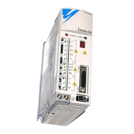
- Page 1 LEGEND Digital Torque Amplifier SGDG User’s Manual Upon receipt of the product and prior to initial operation, read these instructions thoroughly, and retain for future reference.
-
Page 2: Safety-Related Symbols
Any warn- ings provided by YASKAWA must be promptly provided to the end user. YASKAWA offers an express warranty only as to the quality of its products in conforming to standards and specifications published in YASKAWA’s manual. -
Page 3: Icon Display
Icon Display The following icons were designed so as to aid in understanding the type of descriptive content. The icons are displayed where needed to aid in comprehension. Major items which should be memorized. In addition、 this can be a minor item which does not reach the level of damage to the machine, such as the generation of an alarm display. -
Page 4: Outline Of Manual
Outline of Manual Thank you for purchasing the LEGEND Digital torque amplifier. Use this product with a full understanding of conditions such as product specifications, usage limits, etc. This manual explains the following areas for users of the LEGEND Digital torque amplifier. •... -
Page 5: Safety Notes
Safety Notes In this manual, we will describe important cautionary items which should always be observed regarding usage, inspection upon receipt of product, mounting, wiring, operation, and maintenance/inspection. ■ Inspection Upon Receipt of Product CAUTION • Use the servomotors and amplifiers in the designated combinations. (See “3.5 Combinations”... -
Page 6: Operation
CAUTION • Do not connect a three-phase power supply to the digital torque amplifier output terminals U, V, and W. Doing so may result in injury or fire. • Securely fasten the screws for the power terminals and motor terminals. Failure to do say may result in fire. -
Page 7: General Cautionary Items
• To order additional copies of this manual, contact your Yasakwa representative, or the nearest Yaskawa sales office printed on the back of this manual with the document number written on the cover. -
Page 8: Table Of Contents
Table of Contents Safety-Related Symbols ..................i Icon Display ......................ii Outline of Manual ....................iii Safety Notes......................iv Inspection Upon Receipt of Product............iv Mounting ....................iv Wiring ...................... iv Operation ....................v Maintenance/Inspection ................v General Cautionary Items ............... vi Warning Label ..................vi Chapter 1: Interpretation of Model Number ............ - Page 9 Table of Contents Example of I/O Signal Connection ............16 Connector (CN1) Terminal Array List............ 17 CN1 Specifications................17 I/O Signal Names and Their Functions ..........18 Command Input Circuit and Interface ........... 20 Sequence Input Circuit and Interface............ 20 Output Circuits and Interfaces...............
- Page 10 Table of Contents Output Phase Form................45 PG Divider Setting................. 46 4.4 Analog Monitor..................47 4.5 Regenerative Resistor Selection ............. 47 External Regen Resistors ..............48 For Digital Torque Amplifiers of 400W Capacity or Less ...... 48 For Digital Torque Amplifiers of 500W Capacity or More...... 51 Calculating Regen Energy ..............
-
Page 12: Chapter 1: Interpretation Of Model Number
1.1 Rotary Motor Type 1. Interpretation of Model Number 1.1 Rotary Motor Type SGMPH - 01 A A A 2 S D Σ-II Series SGMPH only Servo Motor ⑧ Brake/Oil Seal Specifications Series Name w/o brake or oil seal SGMAH w/ oil seal SGMPH w/ 24V brake... -
Page 13: Linear Motor Type
1.2 Linear Motor Type 1.2 Linear Motor Type ■ Motor Coils SGL G W - 40 A 140 A W Option Specifications P: w/ Hall sensor only. W: w/ Hall sensor and Linear Σ Series Motor Serial Converter. The Serial Converter is required for operation with Motor Type LEGEND Digital Torque... -
Page 14: T-Type Iron Core
1.4 T-Type Iron Core 1.4 T-Type Iron Core ■ Motor Coil Type: SGLTW-20A □□□ A(P), SGLTW -35A □□□ A(P) Min. 100 Hall Sensor Type: SGLTW-40A □□□ A(P), SGLTW -80A □□□ A(P) Min. 64 Max. Cont. External Dimensions (mm) Model Mass Thrust Thrust SGLTW-... -
Page 15: F-Type Iron Core
1.5 F-Type Iron Core 1.5 F-Type Iron Core ■ Motor Coil Min. 50 Hall Sensor Max. Cont. External Dimensions (mm) Model Mass Thrust Thrust SGLFW- (kg) 20A090A(P) 20A120A(P) 35A120A(P) 35A230A(P) 50A200A(P) 71.5 50A380A(P) 1200 71.5 1ZA200A(P) 1200 1ZA380A(P) 2400 12.2... -
Page 16: Digital Torque Amplifier
1.6 Digital Torque Amplifier 1.6 Digital Torque Amplifier SGDG - 10 G LEGEND SGDG Servo Amplifier Maximum applied motor capacity (see table below) Voltage G: 90V~253V Model @T: Torque/Force Control Maximum Capacity of Applied Motor Applied Motor Capacity Maximum Capacity (kW) Symbol Note: Keep the following in mind in SGDG digital torque amplifier and SGDG/SGL□W... -
Page 17: Serial Converter Unit
1.7 Serial Converter Unit 1.7 Serial Converter Unit △△△ JZDP - A○○○ Conversion unit type (see table below) Compatible Motor Numbers Varies according to compatible motors (see table below) Serial Converter Unit Type Model Classifications Model Model Usage Scale Hall Sensor (Y/N?) JZDP- By Haidenhain A003... - Page 18 1.7 Serial Converter Unit Serial Converter Units and Applied Motors Serial Converter Unit Model Serial Converter Unit Model Applied Motor Applied Motor JZDP-A00 □ - □□□ JZDP-A00 □ - □□□ SGLGW-40A140A(P) SGLTW-20A460A(P) SGLGW-40A253A(P) SGLTW-35A170A(P) SGLGW-40A365A(P) SGLTW-35A320A(P) SGLGW-60A140A(P) SGLTW-35A460A(P) SGLGW-60A253A(P) SGLFW-20A090A(P) SGLGW-60A365A(P) SGLFW-20A120A(P) SGLTW-40A400A(P)
- Page 19 Notes:...
-
Page 20: Chapter 2: Wiring
2.1 Main Circuit Wiring 2. Wiring 2.1 Main Circuit Wiring Here we will show representative examples of main circuit wiring, the functions of the main circuit terminals, as well as the power input sequence, etc. Observe the following cautionary items when wiring. CAUTION •... - Page 21 2.1 Main Circuit Wiring Table 2.1: Main Circuit Terminal Names and their Functions (Continued) Terminal Name Function Code Connection not normally needed. Connect an external regen resistor (provided by 100W/400W customer) between B1-B2 if regen capability is insufficient. (Note)There is no B3 terminal. External Regen B1, B2 or Resistor Connection...
- Page 22 2.1 Main Circuit Wiring HEAT SINK SYSTEM (Side) SWITCHES OPTION BOARD (Under the cover) CONNECTOR MAIN POWER CONTROL INDICATOR POWER MAIN INDICATOR POWER TERMINAL STATUS INDICATOR CONTROL WARNING POWER LABEL TERMINAL MOTOR CONNECTION TERMINAL I/O SIGNAL CONNECTOR CN1 GROUNDING TERMINAL ENCODER CONNECTOR...
-
Page 23: Example Of Typical Main Circuit Wiring
2.1 Main Circuit Wiring ■ Example of Typical Main Circuit Wiring A typical wiring example is shown in the figure below. Power 90V~253V Emergency Power Power Stop RY10 Noise Filter Surge Supressor Digital Torque Amplifier SGDG-□□GT +24V Ry10 ALM-SG Figure A Main Circuit Wiring Example... -
Page 24: Power On Sequence Design
2.1 Main Circuit Wiring ■ Power ON Sequence Design Keep the following in mind when designing a Power ON Sequence. • Design the power feed sequence so that the power goes OFF if a “Servo Alarm” is output. See “Figure A Main Circuit Wiring Example” on page 12. •... -
Page 25: Power Terminal Processing
2.1 Main Circuit Wiring Connection Method Strip the insulation of the power lines used. 8 ~ 9mm (.315~.35 in.) 2. Open the terminal block wiring insertion area with a tool. There are two opening methods as shown in figures A and B. •... -
Page 26: Peripheral Device Types And Capacities
2.1 Main Circuit Wiring ■ Peripheral Device Types and Capacities Table 2.3 Shows Servopack device Types and capacities. Table 2.3: Peripheral Device Types and Capacities Recommended Main Power Supply MCCB or Model Noise Filter* Circuit Capacity Per Fuse Magnetic Power Amplifier Capacity Contactor... -
Page 27: Input Signals
2.2 Input Signals 2.2 Input Signals ■ Example of I/O Signal Connection • A typical example of I/O signal connection is shown below. Power 90V~253V AC Power Emergency Power Noise Filter RY10 Stop Surge Supressor Motor SGDG-□□GT Digital Torque Amplifier 24V~12V CN1-26 SV ON ... -
Page 28: Connector (Cn1) Terminal Array List
2.2 Input Signals ■ Connector (CN1) Terminal Array List The CN1 terminal array and its specifications are shown below. CN1 Terminal Layout Encoder Divided Encoder Torque/ Output A Divided Force *PAO phase+ Output A Reference Encoder Input phase- Divided Encoder Output B Divided *PB0... -
Page 29: I/O Signal Names And Their Functions
2.2 Input Signals ■ I/O Signal Names and Their Functions The names and functions of the digital torque amplifier I/O signals are shown below. Input Signals Signal Name Function /S-ON Servo ON • The inverter output is enabled to provide power to the motor. DB -... - Page 30 2.2 Input Signals Output Signals (Continued) Signal Name Pin No. Function Open Terminal Reserved (Note) Do not use empty terminals for relays, etc.
-
Page 31: Command Input Circuit And Interface
2.2 Input Signals ■ Interface Circuit An example is given below of connection of the digital torque amplifier I/O signals to an upper level device. ■ Command Input Circuit and Interface Analog Input Circuit The analog signal is the torque reference signal. The input impedance is as follows. •... -
Page 32: Output Circuits And Interfaces
2.2 Input Signals ■ Output Circuits and Interfaces The output signal circuits of the digital torque amplifier are of the three types shown below. Configure the input circuit on the upper-level device to match each of these output circuits. • Connection with Line Driver Output Circuits The output signals (PAO, *PAO, PBO, *PBO) where the encoder serial data was converter to a 2-phase (A-phase, B-phase) pulse, and the origin pulse signal (PCO, *PCO) are output by the line driver circuit. -
Page 33: Wiring To The Encoder
2.3 Wiring to the Encoder 2.3 Wiring to the Encoder The wiring of the digital torque amplifier to the encoder is described here. ■ Connection to Encoder (CN2) and Output Signal Processing from Digital Torque Amplifier (CN1) Digital Torque Amplifier 1- 33 A-phase 1- 34... - Page 34 Note: The SGMGH and SGMSH servomotor encoder connectors are shown below. • Plug L-type: MS3108B20-29S or • Straight: MS3106B20-29S • Cable Clamp: MS3057-12A Supp. Yaskawa provides a dedicated cable for the encoder. For details, see the following document. • Sigma II Servo System Product Catalog Supplement (Doc.# G-MI#99001x-Sigma II)
-
Page 35: Cable Specifications And Peripheral Devices
2.4 Cable Specifications and Peripheral Devices 2.4 Cable Specifications and Peripheral Devices Ratings and specifications for peripheral devices, as well as cable specifications for digital torque amplifiers are summarized in the tables below. CAUTION Wiring Precautions • Do not bundle or run power and signal lines together in the same duct. Keep power and signal lines at least 11.81”... - Page 36 (AWG): 24, 26, 28, 30 Finished cable Connector Φ 0.63 (Φ16.0) maximum Dimension Cable Use Yaskawa cable, or shielded twisted pair wire. (AWG): 24, 26, 28, 30 Use 22 AWG [0.0005in (0.34mm )] for the encoder power supply and 26 PG Signal Applicable wire AWG [0.0002 in...
-
Page 37: Standard Connection Examples
2.5 Standard Connection Examples 2.5 Standard Connection Examples ■ Single-phase Power Specification (SGDG-01GT, SGDG-04GT) Power 90V~253V AC Power Emergency Power Noise Filter RY10 Stop Surge Supressor Motor SGDG-□□GT Servo amplifier 24V~12V CN1-26 SV ON 5 24V~12V CN1-27 DB_OFF RY10 3.3K Ω ALM+ CN1-13 CN1-34... -
Page 38: 3-Phase Power Specification (Sgdg-10Gt, Sgdg-15Gt)
2.5 Standard Connection Examples ■ 3-Phase Power Specification (SGDG-10GT, SGDG-15GT) Power 90V~253V Ac Emergency Stop Power Power RY10 Noise Filter Surge Supressor Motor SGDG-□□GT Digital Torque Amplifier 24V~12V CN1-26 SV ON 3 CN1-27 24V~12V DB_OFF RY10 3.3K Ω ALM+ CN1-13 CN1-34 SV ON /S... - Page 39 Notes:...
-
Page 40: Chapter 3: Setup
3.1 Linear Motor Mounting 3. Setup 3.1 Linear Motor Mounting CAUTION • In the case of linear motors, various changes can occur according to the direction of the motor mounting and the direction of the encoder mounting. Therefore, perform setup carefully. Careless setup may result in injury. -
Page 41: Storage Temperature
3.2 Rotary Motor Mounting Before Mounting Important The shaft end is treated with a rust-preventative agent. Before mounting the motor, wipe off this rust-preventative agent with a cloth soaked in thinner. When removing the rust-preventative agent, be sure that the thinner does not contact any other parts of the servomotor. -
Page 42: Alignment
3.2 Rotary Motor Mounting ■ Alignment Upon mating to the machine, make sure the motor shaft core and the machine shaft core are coupled in a straight line. Mount the servomotor so that it falls within the alignment accuracy in the figure below. The maximum deviation at all four sides cannot exceed 0.03mm (rotated with the coupling) The maximum deviation at all four sides cannot... -
Page 43: Oil And Water Countermeasures
3.2 Rotary Motor Mounting Table 3.1: Allowable Radial Load/Allowable Thrust Load for Servomotors Allowable Allowable Radial Load Fr Thrust Load Fs Motor Model Reference Diagram [mm] [N(kgf)] [N(kgf)] 68(7) 54(5.5) 68(7) 54(5.5) 78(8) 54(5.5) SGMAH- 245(25) 74(7.5) 245(25) 74(7.5) 392(40) 147(7.5) 78(8) 49(5) -
Page 44: Vibration Resistance
3.2 Rotary Motor Mounting ■ Vibration Resistance Mount the servomotor with the shaft positioned horizontally. The servomotor will withstand the following levels of vibration on all three axes: front-to-back (X), vertical (Y), and side-to-side (Z). • SGMAH, SGMPH: 49m/s (5G) •... -
Page 45: Digital Torque Amplifier Installation
3.3 Digital Torque Amplifier Installation 3.3 Digital Torque Amplifier Installation The SGDG digital torque amplifier is a base-mounted digital torque amplifier. Mount it properly according to the following cautionary items as mistakes in the mounting method can lead to failure of the unit. ■... - Page 46 3.3 Digital Torque Amplifier Installation Installation Cautions on Mounting Conditions Take measures to prevent the influx of corrosive gas. The Mounted in a Location gas will have no immediate effect, but will lead to device Exposed to Corrosive failures in the electronic components and contact-related devices.
- Page 47 3.3 Digital Torque Amplifier Installation Digital Torque Amplifier Mounting Standards Observe the standards for mounting into a control panel shown in the figure below, including those cases where multiple digital torque amplifiers are installed in parallel within a control panel (hereafter referred to as a “parallel platform”). 50mm or more 50mm or...
-
Page 48: Switch Settings
3.4 Switch Settings 3.4 Switch Settings ■ SW1 Function Selection Switch (dip switches) Switch No. Function At OFF At ON Default Setting Status After DB Stop Release DB after Continue DB after During Base Block motor stop motor stop Torque Reference Filter DC-Power Input AC-Power Input Input Power Selection... -
Page 49: Sw3 Pg Divider Setting (Rotary Switch)
3.4 Switch Settings ■ SW3 PG Divider Setting (rotary switch) For a 13-bit Rotary Motor Setting PG Divider Setting** Setting PG Divider Setting** 8192 P/R 3000 P/R 8000 P/R 2500 P/R 7200 P/R 2048 P/R 6000 P/R 2000 P/R 5000 P/R 1800 P/R 4096 P/R 1600 P/R... -
Page 50: Combinations
3.5 Combinations 3.5 Combinations Digital Torque amplifier and motor combinations are shown below. ■ Combinations with Rotary Motors SGMAH Digital Torque Compatible Motor Models Amplifier Model SGDG-01GT SGMAH-A3B SGMAH-A5B SGMAH-A3A SGMAH-A5A SGMAH-01A SGDG-04GT SGMAH-01B SGMAH-02B SGMAH-02A SGMAH-04A SGDG-10GT SGMAH-08A SGMPH Digital Torque Compatible Motor Models Amplifier Model... -
Page 51: Linear Motor Combinations
3.5 Combinations SGMSH Digital Torque Compatible Motor Models Amplifier Model SGMSH-10 □ A SGDG-10GT SGDG-15GT SGMSH-15 □ A ■ Linear Motor Combinations Digital Torque Linear Motor Models Amplifier Model SGLGW-40A140A SGDG-01GT SGDG-04GT SGLGW-40A253A SGLGW-40A365A SGLGW-60A140A SGLGW-60A253A SGLFW-20A090A SGLFW-20A120A SGLFW-35A120A SGDG-10GT SGLTW-20A320A SGLTW-35A170A SGLTW-35A320A... -
Page 52: Chapter 4: Description Of Functions
4.1 Torque/Force Control 4. Description of Functions 4.1 Torque/Force Control This is the torque/force control-dedicated mode. This control mode inputs the torque/force reference from CMD-IN (CN1-3 & CN1-4). Amplifier CMD-IN C M D -I N CN1-3 C N 1-3 CN1-4 C N 1-4 4.2 Protection Sequence Design This section describes the methods for integrating a protective sequence for safety purposes... -
Page 53: Servo On Input
4.2 Protection Sequence Design Be sure to configure the external circuit so that the main power to the digital torque amplifier goes OFF at alarm output. CN1–34, 35 is “closed”, ON State Normal State CN1–34 is level “Low” CN1–34, 35 is “open”, OFF State Alarm State CN1–34 is level “High”... -
Page 54: Db Off Input
4.2 Protection Sequence Design ■ DB OFF Input Sequence Input Signal: The basic connection and handling method for the (DB OFF) signal is shown below. This is used to forcibly release the “DB stop state” during Servo OFF from the upper-level device. 24V Power Amplifier +24V... -
Page 55: Encoder Signal Output
4.3 Encoder Signal Output 4.3 Encoder Signal Output The output signal following division within the digital torque amplifier of the encoder output can be output to an external device. Upper-Level Digital Torque Device Amplifier Encoder A-Phase Serial Data Division B-Phase C-Phase Circuit The output circuit is a line driver output. -
Page 56: I/O Signals
4.3 Encoder Signal Output ■ I/O Signals The details on the output signal are as follows: Output → PAO CN1-20 Encoder Output A-phase Output → *PAO CN1-21 Encoder Output /A-phase Output → PBO CN1-22 Encoder Output B-phase Output → *PBO CN1-23 Encoder Output /B-phase Output →... -
Page 57: Pg Divider Setting
4.3 Encoder Signal Output ■ PG Divider Setting Set the pulse division ratio by the following switches. Delivery Setting Range Setting Unit PG Divider 16,000~131,072 (Rotary 17-bit) 65,536 Setting 1000~8192 (Rotary 13-bit) 8192 1/256~1/2 (Linear Motor) 1/20 Set the number of output pulses output by the encoder output signals (PAO, *PAO, PBO, *PBO). -
Page 58: Analog Monitor
4.4 Analog Monitor 4.4 Analog Monitor The following signals can be monitored in the analog voltage form. 1CN Pin No. Signal Name Content Analog Monitor 1 Motor speed : 1V/1000r/min or 1V/1000mm/sec Analog Monitor 2 Torque = 5V/Max. Torque The analog monitor output voltage is 8VDC (Max.). The output voltage will invert if it exceeds 8VDC. -
Page 59: External Regen Resistors
4.5 Regenerative Resistor Selection ■ External Regen Resistors (1) If the power resistor is used at the rated load rate, resistor temperatures will reach 200°C~300°C. Be sure to derate before using. Check with the manufacturer for the load characteristics of the resistor. Use at a load rating Important of 20% or less when using natural cooling (natural convection cooling), and at 50% or less when forced air cooling is used. - Page 60 4.5 Regenerative Resistor Selection Regenerative Unit Specifications JUSP-RG08 Type Remarks JUSP-RG08D Applicable Servopack SGDG Servopack Regenerative Working Voltage 380Vdc Ω Regenerative Processing Current 8Adc Regenerative resistance:50 Regenerative resistance Error Detection Function disconnection, regenerative transistor fault, overvoltage Normally closed contact (open Alarm Output when protective function 200V operation ok...
- Page 61 4.5 Regenerative Resistor Selection Connecting the JUSP-RG08D to the SGDG-01GT/SGDG-04GT a) A regenerative unit has the following fault detection functions: • Detecting disconnection in a regenerative resistor • Detecting faults in a regenerative resistor • Detecting overvoltage b) When one of these fault detection functions operates, the internal alarm relay is actuated.
-
Page 62: For Digital Torque Amplifiers Of 500W Capacity Or More
4.5 Regenerative Resistor Selection ■ For Digital Torque Amplifiers of 500W Capacity or More Open terminals B2-B3 on the digital torque amplifier (remove the wire), and connect the regen resistor between terminals B1-B2. Amplifier Regen Resistor Be sure to remove the lead wire between B2-B3. - Page 63 Notes:...
-
Page 64: Chapter 5: Servo System Maintenance/Inspection
Determine the usage conditions and environment, and then decide an appropriate inspection period. Do not disassemble the servomotor for maintenance/inspection. Contact your Yaskawa representative or sales office if the servomotor is to be disassembled. -
Page 65: Digital Torque Amplifier Inspection
The components in the table below are subject to mechanical wear or degradation over time. Inspect these periodically for purposes of preventative maintenance. Digital torque amplifiers overhauled by Yaskawa are shipped with their system switches returned to their factory default settings. Be sure to verify these switches before operating. -
Page 66: Alarms
5.3 Alarms 5.3 Alarms POWER ON: Green LED turns ON at control power ON. CHARGE LED: Red LED turns ON at main circuit power ON. ■ 7-Segment LED Base Block Normal Status Servo ON ■ Alarm List Alarm Alarm Name Content Display SW2, SW3 are not set during linear motor... - Page 67 5.3 Alarms Alarm Alarm Name Content Display Communication error between encoder and digital torque amplifier. Encoder Communication between the encoder and Communication Error digital torque amplifier failed three times in succession. Runaway Detection Motor runaway*. Checksum error in EEPROM within encoder Error in the number of pulses in encoder rotation...
-
Page 68: Appendix A:host Controller Connection Examples
Appendix A: Host Controller Connection Examples Appendix A:Host Controller Connection Examples This appendix provides examples of SGDG digital torque amplifier connection to typical host controllers. Please refer to the manuals of the host controllers for more details before actually connecting to them. A.1 Connecting the Galil IMC-1900/2900 LEGEND - Galil, Minimum Servo Interface SGDG, CN1... -
Page 69: Connecting The Delta Tau Pmac2
Appendix A: Host Controller Connection Examples A.2 Connecting the Delta Tau PMAC2 LEGEND - Delta Tau PMAC2, Minimum Servo Interface SGDG, CN1 ACC - 8E CMD-IN DACnA+ TBx - 1 AGND TBx - 3 CHAn+ TBy - 1 CHAn- TBy - 2 CHBn+ TBy - 3 CHBn-... -
Page 70: Connecting The Mei Pcx/Dsp
Appendix A: Host Controller Connection Examples A.3 Connecting the MEI PCX/DSP LEGEND - MEI PCX/DSP, Minimum Servo Interface SGDG, CN1 CMD-IN +/-10V Analog Out n AGND n Encoder A+ n Encoder A- n Encoder B+ n Encoder B- n Enc Index+ n Enc Index- n SV ON5 Amp Enable... -
Page 71: Connecting The Acroloop Acr-8010
Appendix A: Host Controller Connection Examples A.4 Connecting the Acroloop ACR-8010 LEGEND - Acroloop (ACR-8010), Minimum Servo Interface SGDG, CN1 CMD-IN ASIG-x Torque Reference should be mapped to one of these AGND-x analog outputs CHAn CHAn' CHBn CHBn' MRKn MRKn' SV ON5 OUT-y Servo on should be... -
Page 72: Appendix B: Installation Conditions For Emc Directives
This section describes the installation conditions that satisfy EMC guidelines for each model of the SGDG digital torque amplifier. Also, it describes the EMC installation conditions satisfied under test conditions prepared by Yaskawa. The actual EMC level may differ depending on actual system configuration, wiring, and other conditions. - Page 73 Appendix B: Installation Conditions for EMC Directives Core Clamp Clamp Core Core Clamp...
- Page 74 Appendix B: Installation Conditions for EMC Directives Core Clamp Clamp Core Core Clamp...
-
Page 75: The Cable Core
Appendix B: Installation Conditions for EMC Directives ■ Cable Core and Cable Clamp ■ The Cable Core Attach the core on the cable as shown below: Cable Model Note: The diagram shows two turns of the cable ESD-SR-25 Quantity Cable Turn Manufacturer Tokin Corp. -
Page 76: Cable Specifications
Appendix B: Installation Conditions for EMC Directives ■ Noise Filter for Brake Power Supply FN2070-6/07 (Made by Schaffner) for servomotors of 0.4kW or less. ■ Cable Specifications Shielded cables should be used for the following cables: AC power input line cable (between the power supply and the noise filter) Servomotor cable (between the digital torque amplifier and the servomotor) Encoder cable (between the digital torque amplifier and the servomotor) Controller cable (between the digital torque amplifier and the controller) - Page 77 Notes:...
- Page 78 INDEX ........Replacement Core-less Type ........ Acroloop ACR-8010 ........Magnet Track Alarms ........ 7-Segment LED ........Analog Monitor ........Delta Tau PMAC2 Digital Torque Amplifier ........Amplifier Fault Brake Power ....Component Replacement ........Noise Filter ........... Cooling ........Inspection Cleaning ..........
- Page 79 ................Galil IMC-1900/2900 Peripherals Power Line ..........Size .......... Stripping Input Circuits ......Terminal Processing ........Command ....... Power ON Sequence ........Sequence Protection Sequence Input Signals ..........Design ........Connection ........... DB OFF ......... Functions ................Names Regen Circuit Error ........
- Page 80 Servomotor ........Inspection Comprehensive ......... External ..........Noise ..........Oil Seal ..........Vibration ................Maximum Capacity .... Vibration Resistance and Class ..........SGDG-01GT ........... SGLTW -35A ........... SGLTW -80A ..........SGLTW-20A ..........SGLTW-40A Smoothing Capacitor ........Replacement ........Specifications ......
- Page 81 YASKAWA ELECTRIC AMERICA, INC. 2121 Norman Drive South, Waukegan, IL 60085, U.S.A. Phone: (847) 887-7000 Fax: (847) 887-7310 Internet: http://www.yaskawa.com MOTOMAN INC. 805 Liberty Lane, West Carrollton, OH 45449, U.S.A. Phone: (937) 847-6200 Fax: (937) 847-6277 Internet: http://www.motoman.com YASKAWA ELETRICO DO BRASIL COMERCIO LTDA.