Siemens SINAMICS V20 Operating Instructions Manual
Hide thumbs
Also See for SINAMICS V20:
- Operating instructions manual (426 pages) ,
- Getting started (66 pages) ,
- Manual (40 pages)
Table of Contents
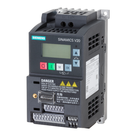
SINAMICS V20 Inverter
SINAMICS
SINAMICS V20 Inverter
Operating Instructions
09/2014
A5E34559884
___________________
___________________
___________________
___________________
___________________
___________________
___________________
___________________
___________________
___________________
___________________
1
2
3
4
5
6
7
8
A
B
Table of Contents

Related Manuals for Siemens SINAMICS V20


Summary of Contents for Siemens SINAMICS V20
- Page 1 ___________________ SINAMICS V20 Inverter Preface ___________________ Safety instructions ___________________ SINAMICS Introduction ___________________ Mechanical installation SINAMICS V20 Inverter ___________________ Electrical installation ___________________ Commissioning Operating Instructions ___________________ Communicating with the PLC ___________________ Parameter list ___________________ Faults and alarms ___________________ Technical specifications ___________________...
- Page 2 Note the following: WARNING Siemens products may only be used for the applications described in the catalog and in the relevant technical documentation. If products and components from other manufacturers are used, these must be recommended or approved by Siemens. Proper transport, storage, installation, assembly, commissioning, operation and maintenance are required to ensure that the products operate safely and without any problems.
-
Page 3: Preface
Preface Purpose of this manual This manual provides you with information about the proper installation, commissioning, operation, and maintenance of SINAMICS V20 inverters. SINAMICS V20 user documentation components Document Content Available languages Operating Instructions (this manual) English Chinese French German... - Page 4 +55 11 3833 4040 India +91 22 2760 0150 Korea +82 2 3450 7114 Turkey +90 (216) 4440747 United States of America +1 423 262 5710 Further service contact information: Support contacts (http://support.automation.siemens.com/WW/view/en/16604999) SINAMICS V20 Inverter Operating Instructions, 09/2014, A5E34559884...
-
Page 5: Table Of Contents
Mounting orientation and clearance ..................25 Cabinet panel mounting (frame sizes A to E) ................. 26 SINAMICS V20 Flat Plate variant ................... 28 Push-through mounting (frame sizes B to E) ................30 DIN rail mounting (frame sizes A to B) ................... 33 Electrical installation.......................... -
Page 6: Table Of Contents
Communicating with the PLC ....................... 133 USS communication ......................133 MODBUS communication ....................138 Parameter list ............................147 Introduction to parameters ....................147 Parameter list ........................151 Faults and alarms ..........................281 Faults ........................... 281 SINAMICS V20 Inverter Operating Instructions, 09/2014, A5E34559884... -
Page 7: Table Of Contents
Shield connection kits ......................333 B.1.10 Memory card ......................... 336 B.1.11 RS485 termination resistor ....................336 B.1.12 DIN rail mounting kits ......................336 B.1.13 User documentation ......................337 Spare parts - replacement fans .................... 337 Index..............................341 SINAMICS V20 Inverter Operating Instructions, 09/2014, A5E34559884... - Page 8 Table of contents SINAMICS V20 Inverter Operating Instructions, 09/2014, A5E34559884...
-
Page 9: Safety Instructions
Touching live components can result in death or severe injury. • Only use power supplies that provide SELV (Safety Extra Low Voltage) or PELV- (Protective Extra Low Voltage) output voltages for all connections and terminals of the electronics modules. SINAMICS V20 Inverter Operating Instructions, 09/2014, A5E34559884... - Page 10 • Install devices without a protective housing in a metal control cabinet (or protect the device by another equivalent measure) in such a way that contact with fire is prevented. • Ensure that smoke can only escape via controlled and monitored paths. SINAMICS V20 Inverter Operating Instructions, 09/2014, A5E34559884...
- Page 11 Missing or illegible warning labels can result in accidents involving death or serious injury. • Check that the warning labels are complete based on the documentation. • Attach any missing warning labels to the components, in the national language if necessary. • Replace illegible warning labels. SINAMICS V20 Inverter Operating Instructions, 09/2014, A5E34559884...
- Page 12 As a result of incorrect or changed parameterization, machines can malfunction, which in turn can lead to injuries or death. • Protect the parameterization (parameter assignments) against unauthorized access. • Respond to possible malfunctions by applying suitable measures (e.g. EMERGENCY STOP or EMERGENCY OFF). SINAMICS V20 Inverter Operating Instructions, 09/2014, A5E34559884...
-
Page 13: Safety Instructions For Electromagnetic Fields (Emf)
– Wearing ESD shoes or ESD grounding straps in ESD areas with conductive flooring • Only place electronic components, modules or devices on conductive surfaces (table with ESD surface, conductive ESD foam, ESD packaging, ESD transport container). SINAMICS V20 Inverter Operating Instructions, 09/2014, A5E34559884... -
Page 14: Industrial Security
Siemens recommends strongly that you regularly check for product updates. For the secure operation of Siemens products and solutions, it is necessary to take suitable preventive action (e.g. cell protection concept) and integrate each component into a holistic, state-of-the-art industrial security concept. -
Page 15: Residual Risks Of Power Drive Systems
3. Hazardous shock voltages caused by, for example, – Component failure – Influence during electrostatic charging – Induction of voltages in moving motors – Operation and/or environmental conditions outside the specification – Condensation/conductive contamination – External influences/damage SINAMICS V20 Inverter Operating Instructions, 09/2014, A5E34559884... - Page 16 Assuming that conductive contamination at the installation site can definitely be excluded, a lower degree of cabinet protection may be permitted. For more information about residual risks of the components in a drive system, see the relevant sections in the technical user documentation. SINAMICS V20 Inverter Operating Instructions, 09/2014, A5E34559884...
-
Page 17: Additional Safety Instructions
B(k) 30 mA RCD. • SINAMICS V20 three phase AC 400 V inverters (filtered) with rated power up to 2.2 kW can be operated on a type B(k) 30 mA RCD. For inverters with rated power over 3.0 kW, a type B(k) 300 mA RCD can be used. - Page 18 National Electrical Code and any additional local codes. CAUTION Cable connection Separate the control cables from the power cables as much as possible. Keep the connecting cables away from rotating mechanical parts. SINAMICS V20 Inverter Operating Instructions, 09/2014, A5E34559884...
- Page 19 WARNING Repair and replacement of equipment Repairs on equipment may only be carried out by Siemens Service, by repair centers authorized by Siemens or by authorized personnel who are thoroughly acquainted with all the warnings and operating procedures contained in this manual.
- Page 20 Easy-to-release screw and snap connectors allow you to break the unit down into its component parts. You can recycle these component parts, dispose of them in accordance with local requirements or return them to the manufacturer. SINAMICS V20 Inverter Operating Instructions, 09/2014, A5E34559884...
-
Page 21: Introduction
Introduction Components of the inverter system The SINAMICS V20 is a range of inverters designed for controlling the speed of three phase asynchronous motors. Three phase AC 400 V variants The three phase AC 400 V inverters are available in five frame sizes. - Page 22 0.75 kW 10 A 4.2 A 6SL3210-5BB18-0UV0 6SL3210-5BB18-0AV0 (with single fan) Frame size B 1.1 kW 14.7 A 6.0 A 6SL3210-5BB21-1UV0 6SL3210-5BB21-1AV0 (with single fan) 1.5 kW 19.7 A 7.8 A 6SL3210-5BB21-5UV0 6SL3210-5BB21-5AV0 SINAMICS V20 Inverter Operating Instructions, 09/2014, A5E34559884...
-
Page 23: Inverter Rating Plate
13.6 A 6SL3210-5BB23-0UV0 6SL3210-5BB23-0AV0 Options and spare parts For detailed information of the options and spare parts, refer to Appendices "Options (Page 301)" and "Spare parts - replacement fans (Page 337)". Inverter rating plate SINAMICS V20 Inverter Operating Instructions, 09/2014, A5E34559884... - Page 24 Introduction 2.2 Inverter rating plate SINAMICS V20 Inverter Operating Instructions, 09/2014, A5E34559884...
-
Page 25: Mechanical Installation
Always mount the inverter in an upright position. Mounting clearance ≥ 100 mm Bottom ≥100 mm (for frame sizes B to E, and frame size A without fan) ≥ 85 mm (for fan-cooled frame size A) Side ≥ 0 mm SINAMICS V20 Inverter Operating Instructions, 09/2014, A5E34559884... -
Page 26: Cabinet Panel Mounting (Frame Sizes A To E)
Tightening torque: 1.8 Nm ± 10% Depth of Flat Plate inverter (400 V 0.75 kW variant only) Frame size B Fixings: 4 x M4 screws, nuts, washers Tightening torque: 1.8 Nm ± 10% SINAMICS V20 Inverter Operating Instructions, 09/2014, A5E34559884... - Page 27 Tightening torque: 2.5 Nm ± 10% Frame size D Fixings: 4 x M5 screws, nuts, washers Tightening torque: 2.5 Nm ± 10% Frame size E Fixings: 4 x M5 screws, nuts, washers Tightening torque: 2.5 Nm ± 10% SINAMICS V20 Inverter Operating Instructions, 09/2014, A5E34559884...
-
Page 28: Sinamics V20 Flat Plate Variant
3.3 SINAMICS V20 Flat Plate variant SINAMICS V20 Flat Plate variant The SINAMICS V20 Flat Plate variant is designed to allow greater flexibility in the installation of the inverter. Adequate measures must be taken to ensure the correct heat dissipation, which may require an additional external heatsink outside the electrical enclosure. - Page 29 Mechanical installation 3.3 SINAMICS V20 Flat Plate variant Installing 1. Prepare the mounting surface for the inverter using the dimensions given in Section "Cabinet panel mounting (frame sizes A to E) (Page 26)". 2. Ensure that any rough edges are removed from the drilled holes, the flat plate heatsink is clean and free from dust and grease, and the mounting surface and if applicable the external heatsink are smooth and made of unpainted metal (steel or aluminium).
-
Page 30: Push-Through Mounting (Frame Sizes B To E)
Drill pattern and cut-out (mm) Frame size B Fixings: 4 x M4 screws Tightening torque: 1.8 Nm ± 10% Frame size C Fixings: 4 x M5 screws Tightening torque: 2.5 Nm ± 10% SINAMICS V20 Inverter Operating Instructions, 09/2014, A5E34559884... - Page 31 Drill pattern and cut-out (mm) Frame size D Fixings: 4 x M5 screws Tightening torque: 2.5 Nm ± 10% Frame size E Fixings: 4 x M5 screws Tightening torque: 2.5 Nm ± 10% Depth inside the cabinet SINAMICS V20 Inverter Operating Instructions, 09/2014, A5E34559884...
- Page 32 3.4 Push-through mounting (frame sizes B to E) Mounting Note A gap is reserved at the bottom of the cut-out area to allow fan removal from outside the cabinet without removing the inverter. SINAMICS V20 Inverter Operating Instructions, 09/2014, A5E34559884...
-
Page 33: Din Rail Mounting (Frame Sizes A To B)
● Push-through mounting (frame sizes B to E) (Page 30) Note To install or remove FSA/FSB, you can use a crosshead or flat-bit screwdriver. Installing the frame size A to the DIN rail SINAMICS V20 Inverter Operating Instructions, 09/2014, A5E34559884... - Page 34 Mechanical installation 3.5 DIN rail mounting (frame sizes A to B) Removing the frame size A from the DIN rail SINAMICS V20 Inverter Operating Instructions, 09/2014, A5E34559884...
- Page 35 Mechanical installation 3.5 DIN rail mounting (frame sizes A to B) Installing the frame size B to the DIN rail Removing the frame size B from the DIN rail SINAMICS V20 Inverter Operating Instructions, 09/2014, A5E34559884...
- Page 36 Mechanical installation 3.5 DIN rail mounting (frame sizes A to B) SINAMICS V20 Inverter Operating Instructions, 09/2014, A5E34559884...
-
Page 37: Electrical Installation
Electrical installation Typical system connections Typical system connections SINAMICS V20 Inverter Operating Instructions, 09/2014, A5E34559884... - Page 38 0.75 3RV20 11-1KA10 230/240 9.0 to 12.5 3RV20 21-4BA10 230/240 14.0 to 20.0 3RV20 21-4CA10 230/240 17.0 to 22.0 3RV20 21-4EA10 230/240 27.0 to 32.0 10.0 3RV10 31-4FA10 230/240 28.0 to 40.0 20.0 SINAMICS V20 Inverter Operating Instructions, 09/2014, A5E34559884...
- Page 39 Electrical installation 4.1 Typical system connections Wiring diagram Note The resistance of the potentiometer for each analog input must be ≥ 4.7 Ω. See also "Setting connection macros (Page 63)" SINAMICS V20 Inverter Operating Instructions, 09/2014, A5E34559884...
-
Page 40: Terminal Description
Electrical installation 4.2 Terminal description Terminal description Terminal layout SINAMICS V20 Inverter Operating Instructions, 09/2014, A5E34559884... - Page 41 2.5 mm (10) 1.5 Nm 2.2 kW to 3.0 kW 10 mm 2.4 Nm 4.0 mm 2.4 Nm * Data in brackets indicate the corresponding AWG values. ** With a UL/cUL-certified, suitable fork crimp SINAMICS V20 Inverter Operating Instructions, 09/2014, A5E34559884...
- Page 42 Select delta connection if either a 230/400 V motor on a 400 V inverter or a 120/230 V motor on a 230 V inverter is supposed to operate at 87 Hz instead of 50 Hz. SINAMICS V20 Inverter Operating Instructions, 09/2014, A5E34559884...
- Page 43 Threshold 0 ⇒ 1 (maximum): 11 V Threshold 1 ⇒ 0 (minimum): Input current (guaranteed off): 0.6 mA to 2 mA Input current (maximum on): 15 mA 2-wire Bero compatibility: Response time: 4 ms ± 4 ms SINAMICS V20 Inverter Operating Instructions, 09/2014, A5E34559884...
- Page 44 ● Powering the inverter from the Parameter Loader, when mains power is not available For more information about these two option modules, refer to the topics "Parameter Loader (Page 301)" and "External BOP and BOP Interface Module (Page 305)". SINAMICS V20 Inverter Operating Instructions, 09/2014, A5E34559884...
-
Page 45: Emc-Compliant Installation
This mounting plate must be connected to the cabinet panel and the PE or EMC bus bar. The following diagram shows an example of EMC-compliant installation of the inverter frame size B/C. SINAMICS V20 Inverter Operating Instructions, 09/2014, A5E34559884... - Page 46 2 x ferrites of Type "Seiwa E04SRM563218" or equivalent in the vicinity of the motor terminals of the inverter. Shielding method The following illustration shows an example with and without the shielding plate. SINAMICS V20 Inverter Operating Instructions, 09/2014, A5E34559884...
-
Page 47: Emc-Compliant Cabinet Design
● Cables connecting different zones must be separated and must not be routed within the same cable harness or cable channel. ● All communication (e.g. RS485) and signal cables leaving the cabinet must be shielded. SINAMICS V20 Inverter Operating Instructions, 09/2014, A5E34559884... - Page 48 Electrical installation 4.4 EMC-compliant cabinet design SINAMICS V20 Inverter Operating Instructions, 09/2014, A5E34559884...
-
Page 49: Commissioning
Commissioning Note For a detailed description of parameter settings for the quick commissioning, refer to the topic "Quick commissioning (Page 60)". The built-in Basic Operator Panel (BOP) 5.1.1 Introduction to the built-in BOP SINAMICS V20 Inverter Operating Instructions, 09/2014, A5E34559884... - Page 50 Long press ( > 2 s) Quick parameter number or value edit • Accesses fault information data • Hand/Jog/Auto Press to switch between different modes: Note: Jog mode is only available if the motor is stopped. SINAMICS V20 Inverter Operating Instructions, 09/2014, A5E34559884...
-
Page 51: Inverter Menu Structure
Basic monitoring view of key parameters such as frequen- cy, voltage, current, DC-link voltage, and so on. Setup menu Access to parameters for quick commissioning of the in- verter system. Parameter menu Access to all available inverter parameters. SINAMICS V20 Inverter Operating Instructions, 09/2014, A5E34559884... - Page 52 Commissioning 5.1 The built-in Basic Operator Panel (BOP) SINAMICS V20 Inverter Operating Instructions, 09/2014, A5E34559884...
-
Page 53: Viewing Inverter Status
Available for DDS switching via P0820 and • P0821 Other parameters Multi-indexed parameters These parameters are indexed with the range of indices dependent on the individual parameter. Index-free parameters These parameters are not indexed. SINAMICS V20 Inverter Operating Instructions, 09/2014, A5E34559884... - Page 54 ● To quickly increase or decrease the parameter number, index, or value, press for longer than two seconds. ● To confirm the setting, press ● To cancel the setting, press Example: Editing parameter values SINAMICS V20 Inverter Operating Instructions, 09/2014, A5E34559884...
- Page 55 Example 1: Example 2: Example 3: Editing parameter numbers Editing parameter indices Editing parameter values If a parameter is an array, edit indices as illustrated below: SINAMICS V20 Inverter Operating Instructions, 09/2014, A5E34559884...
-
Page 56: Screen Displays
"8 8 8 8 8" Inverter is busy with internal data processing. "- - - - -" Action not completed or not possible "Pxxxx" Writable parameter "rxxxx" Read-only parameter "inxxx" Indexed parameter SINAMICS V20 Inverter Operating Instructions, 09/2014, A5E34559884... - Page 57 "-APxxx" Current selected application macro "A" "G" "N" "T" "B" "H" "O" "U" "C" "I" "P" "V" "D" "J" "Q" "X" "E" "L" "R" "Y" "F" "M" "S" "Z" 0 to 9 "?" SINAMICS V20 Inverter Operating Instructions, 09/2014, A5E34559884...
-
Page 58: Led States
5.2 Checking before power-on 5.1.6 LED states The SINAMICS V20 has only one LED for status indications. The LED can display orange, green, or red. If more than one inverter state exists, the LED displays in the following order of priority: ●... -
Page 59: Setting The 50/60 Hz Selection Menu
Value Description P0100 Motor base frequency is 50 Hz (default) → Europe [kW] Motor base frequency is 60 Hz → United States/Canada [hp] Motor base frequency is 60 Hz → United States/Canada [kW] SINAMICS V20 Inverter Operating Instructions, 09/2014, A5E34559884... -
Page 60: Starting The Motor For Test Run
The setup menu guides you through the steps required for quick commissioning of the inverter system. It consists of the following four sub-menus: Sub-menu Functionality Motor data Sets nominal motor parameters for quick commissioning Connection macro selection Sets macros required for standard wiring arrangements SINAMICS V20 Inverter Operating Instructions, 09/2014, A5E34559884... - Page 61 Commissioning 5.5 Quick commissioning Sub-menu Functionality Application macro selection Sets macros required for certain common applications Common parameter selection Sets parameters required for inverter performance opti- mization Menu structure SINAMICS V20 Inverter Operating Instructions, 09/2014, A5E34559884...
-
Page 62: Setting Motor Data
Rated motor power factor (cosφ) Visible only when P0100 = 0 or 2 (M COS) P0309[0] ● Rated motor efficiency [%] Visible only when P0100 = 1 (M EFF) Setting 0 causes internal calculation of value. SINAMICS V20 Inverter Operating Instructions, 09/2014, A5E34559884... -
Page 63: Setting Connection Macros
This menu selects which macro is required for standard wiring arrangements. The default one is "Cn000" for connection macro 0. All connection macros only change the CDS0 (command data set 0) parameters. The CDS1 parameters are used for the BOP control. SINAMICS V20 Inverter Operating Instructions, 09/2014, A5E34559884... - Page 64 External push button control Cn007 External push button with analog setpoint Cn008 PID control with analog input reference Cn009 PID control with the fixed value reference Cn010 USS control Cn011 MODBUS RTU control Setting connection macros SINAMICS V20 Inverter Operating Instructions, 09/2014, A5E34559884...
- Page 65 BI: Function of digital output 1 52.3 52.2 Inverter running P0732[0] BI: Function of digital output 2 52.7 52.3 Inverter fault active P0771[0] CI: Analog output Actual frequency P0810[0] BI: CDS bit 0 (Hand/Auto) Hand mode SINAMICS V20 Inverter Operating Instructions, 09/2014, A5E34559884...
- Page 66 Function of digital input 1 ON/OFF P0702[0] Function of digital input 2 Reverse P0703[0] Function of digital input 3 Fault acknowledgement P0704[0] Function of digital input 4 JOG forward P0771[0] CI: Analog output Actual frequency SINAMICS V20 Inverter Operating Instructions, 09/2014, A5E34559884...
- Page 67 P1022[0] BI: Fixed frequency selection 722.5 722.3 bit 2 P1001[0] Fixed frequency 1 Speed low P1002[0] Fixed frequency 2 Speed middle P1003[0] Fixed frequency 3 Speed high P0771[0] CI: Analog output Actual frequency SINAMICS V20 Inverter Operating Instructions, 09/2014, A5E34559884...
- Page 68 P1021[0] BI: Fixed frequency selection 722.4 722.1 bit 1 P1022[0] BI: Fixed frequency selection 722.5 722.2 bit 2 P1023[0] BI: Fixed frequency selection 722.6 722.3 bit 3 P0771[0] CI: Analog output Actual frequency SINAMICS V20 Inverter Operating Instructions, 09/2014, A5E34559884...
- Page 69 Function of digital input 1 ON/OFF P0702[0] Function of digital input 2 Fixed speed bit 0 P0703[0] Function of digital input 3 Fixed speed bit 1 P0704[0] Function of digital input 4 Fault acknowledgement SINAMICS V20 Inverter Operating Instructions, 09/2014, A5E34559884...
- Page 70 Function of digital input 4 MOP down pulse P0727[0] Selection of 2/3-wire method 3-wire ON pulse + OFF1/hold + Reverse P0771[0] CI: Analog output Actual frequency P0731[0] BI: Function of digital output 1 52.3 52.2 Inverter running SINAMICS V20 Inverter Operating Instructions, 09/2014, A5E34559884...
- Page 71 Function of digital input 1 OFF hold P0702[0] Function of digital input 2 Forward pulse + ON P0703[0] Function of digital input 3 Reverse pulse + ON P0704[0] Function of digital input 4 Fault acknowledgement SINAMICS V20 Inverter Operating Instructions, 09/2014, A5E34559884...
- Page 72 AI2, 0 mA to 20 mA P0771[0] CI: Analog output Actual frequency P0731[0] BI: Function of digital output 1 52.3 52.2 Inverter running P0732[0] BI: Function of digital output 2 52.7 52.3 Inverter fault active SINAMICS V20 Inverter Operating Instructions, 09/2014, A5E34559884...
- Page 73 P2222[0] BI: Fixed PID setpoint select 722.5 722.3 BICO connection DI4 bit 2 P2253[0] CI: PID setpoint 2224 PID setpoint = fixed value P2264[0] CI: PID feedback 755.0 755.1 PID feedback = AI2 SINAMICS V20 Inverter Operating Instructions, 09/2014, A5E34559884...
- Page 74 RS485 as the command source P1000[0] Selection of frequency RS485 as the speed setpoint P2023[0] RS485 protocol selection MODBUS RTU protocol P2010[0] USS/MODBUS baudrate Baudrate 9600 bps P2021[0] MODBUS address MODBUS address for inverter SINAMICS V20 Inverter Operating Instructions, 09/2014, A5E34559884...
-
Page 75: Setting Application Macros
Factory default setting. Makes no parameter changes. AP010 Simple pump applications AP020 Simple fan applications AP021 Compressor applications The minus sign indicates that this macro is the currently AP030 Conveyor applications selected macro. SINAMICS V20 Inverter Operating Instructions, 09/2014, A5E34559884... - Page 76 Search for the speed of the running motor with a heavy inertia load so that the motor runs up to the setpoint P1210[0] Automatic restart Fault acknowledgement at power-on P1080[0] Minimum frequency Inverter running at a lower speed inhibited SINAMICS V20 Inverter Operating Instructions, 09/2014, A5E34559884...
- Page 77 Starting boost 0 Boost only effective when accelerating for the first time (standstill) P1120[0] Ramp-up time 10 Ramp-up time from zero to maximum frequency P1121[0] Ramp-down Ramp-down time from maximum frequency to zero time SINAMICS V20 Inverter Operating Instructions, 09/2014, A5E34559884...
-
Page 78: Setting Common Parameters
(RMP DN) (PID F1) P1058[0] JOG frequency P2202[0] Fixed PID frequen- cy setpoint 2 (JOG P) (PID F2) P1060[0] JOG ramp-up time P2203[0] Fixed PID frequen- cy setpoint 3 (JOG UP) (PID F3) SINAMICS V20 Inverter Operating Instructions, 09/2014, A5E34559884... -
Page 79: Quick Commissioning Through The Parameter Menu
Range: 0 to 40000 P0335[0] Motor cooling Set according to the actual motor cooling method = 0: Self-cooled (factory default) = 1: Force-cooled = 2: Self-cooled and internal fan = 3: Force-cooled and internal fan SINAMICS V20 Inverter Operating Instructions, 09/2014, A5E34559884... - Page 80 = 4: V/f with linear eco = 5: V/f for textile applications = 6: V/f with FCC for textile applications = 7: V/f with quadratic eco = 19: V/f control with independent voltage setpoint SINAMICS V20 Inverter Operating Instructions, 09/2014, A5E34559884...
-
Page 81: Function Commissioning
Function commissioning 5.6.1 Overview of inverter functions The list below provides an overview of the main functions that the SINAMICS V20 supports. For detailed description of individual parameters, see Chapter "Parameter list (Page 147)". ● 2/3 wire control (P0727) ● 50/60 Hz customization (Page 59) (P0100) ●... - Page 82 ● Protection of user-defined parameters (P0011, P0012, P0013) ● Skip frequency and resonance damping (P1091 to P1101, P1338) ● Sleep (hibernation) mode (Page 120) (P2365 to P2367) ● Slip compensation (P1334 to P1338) SINAMICS V20 Inverter Operating Instructions, 09/2014, A5E34559884...
-
Page 83: Commissioning Basic Functions
OFF1 is directly activated. The inverter is braked by OFF1 with the ramp-down time P1121. If the output frequency falls below the parameter value P2167 and if the time in P2168 has expired, then the inverter pulses are cancelled. SINAMICS V20 Inverter Operating Instructions, 09/2014, A5E34559884... - Page 84 → P0700 = 2 and OFF2 is selected using digital input 2 → P0702 = 3). • OFF2 is active low. • When various OFF commands are selected simultaneously, the following priority applies: OFF2 (highest priority) – OFF3 – OFF1. SINAMICS V20 Inverter Operating Instructions, 09/2014, A5E34559884...
- Page 85 P0848 (BI: 1. OFF3) and P0849 (BI: 2. OFF3). • OFF3 is active low. • When various OFF commands are selected simultaneously, the following priority applies: OFF2 (highest priority) – OFF3 – OFF1 SINAMICS V20 Inverter Operating Instructions, 09/2014, A5E34559884...
-
Page 86: Running The Inverter In Jog Mode
Range: 0.00 to 550.00 (factory default: 5.00) P1059[0...2] JOG frequency left [Hz] This parameter determines the frequency at which the inverter will run while JOG left is selected. Range: 0.00 to 550.00 (factory default: 5.00) SINAMICS V20 Inverter Operating Instructions, 09/2014, A5E34559884... -
Page 87: Setting The Voltage Boost
V/f curves. Range: 0.0 to 250.0 (factory default: 50.0) The voltage boost is effective over the complete frequency range whereby the value continually decreases at high frequencies. SINAMICS V20 Inverter Operating Instructions, 09/2014, A5E34559884... - Page 88 • setpoint is reduced to less than present ramp output • Range: 0.0 to 250.0 (factory default: 0.0) The voltage boost is only effective when accelerating for the first time (stand- still). SINAMICS V20 Inverter Operating Instructions, 09/2014, A5E34559884...
-
Page 89: Setting The Pid Controller
This parameter defines source of DOWN command. Possible sources: 19.14 (BOP), 722.x (Digital Input), 2036.14 (USS on RS485) Additional commissioning parameters P2251 PID mode = 0: PID as setpoint (factory default) = 1: PID as trim source SINAMICS V20 Inverter Operating Instructions, 09/2014, A5E34559884... - Page 90 BO: PID fixed frequency status r2245 CO: PID-MOP input frequency of the RFG [%] r2250 CO: Output setpoint of PID-MOP [%] r2260 CO: PID setpoint after PID-RFG [%] P2261 PID setpoint filter time constant [s] SINAMICS V20 Inverter Operating Instructions, 09/2014, A5E34559884...
-
Page 91: Setting The Braking Function
5. The required braking current P1232 is then impressed for the selected braking time P1233. The status is displayed using signal r0053 bit 00. The inverter pulses are inhibited after the braking time has expired. SINAMICS V20 Inverter Operating Instructions, 09/2014, A5E34559884... - Page 92 This state is displayed using signal r0053 bit 00. 4. After DC braking has been cancelled, the inverter accelerates back to the setpoint frequency until the motor speed matches the inverter output frequency. SINAMICS V20 Inverter Operating Instructions, 09/2014, A5E34559884...
- Page 93 While DC braking, there is no other way of influencing the inverter speed using an external control. When parameterizing and setting the inverter system, it should be tested using real loads as far as possible. SINAMICS V20 Inverter Operating Instructions, 09/2014, A5E34559884...
- Page 94 = 1: Enabled (factory default) It is recommended to set P1254 = 1 (auto detection of Vdc switch-on levels enabled). Note that auto detection only works when the inverter has been in standby for over 20s. SINAMICS V20 Inverter Operating Instructions, 09/2014, A5E34559884...
- Page 95 Contrary to DC and compound braking, this technique requires that an external braking resistor is installed. For more information about the dynamic braking module, refer to the Appendix "Dynamic braking module (Page 312)". SINAMICS V20 Inverter Operating Instructions, 09/2014, A5E34559884...
- Page 96 The average power of the dynamic braking module (braking chopper) cannot exceed the power rating of the braking resistor. Duty cycle cycle 12.0 228.0 240.0 0.05 12.6 114.0 126.6 0.10 14.2 57.0 71.2 0.20 22.8 22.8 45.6 0.50 100% Infinite Infinite 1.00 SINAMICS V20 Inverter Operating Instructions, 09/2014, A5E34559884...
- Page 97 Braking resistors, which are to be mounted on the inverter, must be designed so that they can tolerate the power dissipated. If an unsuitable braking resistor is used, there is a danger of fire and the associated inverter will be significantly damaged. SINAMICS V20 Inverter Operating Instructions, 09/2014, A5E34559884...
- Page 98 Commissioning 5.6 Function commissioning Motor holding brake The motor holding brake prevents the motor from undesirable turning when the inverter is switched-off. The inverter has internal logic to control a motor holding brake. SINAMICS V20 Inverter Operating Instructions, 09/2014, A5E34559884...
- Page 99 It is not permissible to use the motor holding brake as operating brake. The reason for this is that generally it is only designed for a limited number of emergency braking operations. SINAMICS V20 Inverter Operating Instructions, 09/2014, A5E34559884...
-
Page 100: Setting The Ramp Time
Ramp-down time [s] This parameter sets the time taken for motor to decelerate from maximum motor frequency (P1082) down to standstill when no rounding is used. Range: 0.00 to 650.00 (factory default: 10.00) SINAMICS V20 Inverter Operating Instructions, 09/2014, A5E34559884... - Page 101 This parameter defines rounding time at start of ramp-down. Range: 0.00 to 40.00 (factory default: 0.00) P1133[0...2] Ramp-down final rounding time [s] This parameter defines rounding time at end of ramp-down. Range: 0.00 to 40.00 (factory default: 0.00) SINAMICS V20 Inverter Operating Instructions, 09/2014, A5E34559884...
-
Page 102: Setting The Imax Controller
The Imax controller reduces inverter current if the output current exceeds the maximum output current limit (r0067). This is achieved by reducing the inverter's output frequency or output voltage. SINAMICS V20 Inverter Operating Instructions, 09/2014, A5E34559884... - Page 103 P1346[0...2] Imax voltage controller integral time This parameter defines the integral time constant of the Imax voltage controller. Range: 0.000 to 50.000 (factory default: 0.300) r0056.13 Status of motor control: Imax controller active SINAMICS V20 Inverter Operating Instructions, 09/2014, A5E34559884...
-
Page 104: Setting The Vdc Controller
If ramp-down time is too short, the inverter may display the alarm A911 which means the DC link voltage is too high. The Vdc controller dynamically controls the DC link voltage to prevent overvoltage trips on high inertia systems. SINAMICS V20 Inverter Operating Instructions, 09/2014, A5E34559884... -
Page 105: Setting The Load Torque Monitoring Function
P0305 (rated motor cur- rent). Range: 0.0 to 10.0 (factory default: 3.0) P2180 Delay time for no-load identification Defines the delay time for detecting a missing output load. [ms] Range: 0 to 10000 (factory default: 2000) SINAMICS V20 Inverter Operating Instructions, 09/2014, A5E34559884... - Page 106 Range: 0.0 to 99999.0 (factory default: value in r0333) P2190[0...2] Lower torque threshold 3 [Nm] Range: 0.0 to 99999.0 (factory default: 0.0) P2192[0...2] Load monitoring delay time [s] Range: 0 to 65 (factory default: 10) SINAMICS V20 Inverter Operating Instructions, 09/2014, A5E34559884...
-
Page 107: Commissioning Advanced Functions
P3356[0...2] Super torque boost time [s] This parameter sets the time for which the additional boost is applied, when the output frequency is held at P3354. Range: 0.0 to 20.0 (factory default: 5.0) SINAMICS V20 Inverter Operating Instructions, 09/2014, A5E34559884... - Page 108 ● Maintains for P3356 s with the boost level specified by P3355 ● Reverts boost level to that specified by P1310, P1311, and P1312 ● Reverts to "normal" setpoint and allows output to ramp using P1120 SINAMICS V20 Inverter Operating Instructions, 09/2014, A5E34559884...
-
Page 109: Starting The Motor In Hammer Start Mode
Range: 0.0 to 200.0 (factory default: 150.0) P3358[0...2] Number of hammer cycles This parameter defines the number of times the hammer start boost level is applied. Range: 1 to 10 (factory default: 5) SINAMICS V20 Inverter Operating Instructions, 09/2014, A5E34559884... - Page 110 ● Ramp up to P3354 Hz with the boost level specified by P1310, P1311, and P1312 ● Revert boost level to that specified by P1310, P1311, and P1312 ● Revert to "normal" setpoint and allow output to ramp using P1120 SINAMICS V20 Inverter Operating Instructions, 09/2014, A5E34559884...
-
Page 111: Starting The Motor In Blockage Clearing Mode
Blockage clearing reverse time [s] This parameter sets the time for which the inverter runs in the opposite direction to the setpoint during the reverse sequence. Range: 0.0 to 20.0 (factory default: 5.0) SINAMICS V20 Inverter Operating Instructions, 09/2014, A5E34559884... - Page 112 – Ramp down to 0 Hz using normal ramp time as specified in P1121 – Ramp or step (depending on P3363) to P3361 Hz in opposite direction to the setpoint ● Revert to "normal" setpoint and allow output to ramp using P1120. SINAMICS V20 Inverter Operating Instructions, 09/2014, A5E34559884...
-
Page 113: Running The Inverter In Economy Mode
Economy mode factor [%] This parameter displays the calculated economy mode factor (range: 80% to 120%) applied to the demanded output voltage. If this value is too low, the system may become unstable. Function diagram SINAMICS V20 Inverter Operating Instructions, 09/2014, A5E34559884... -
Page 114: Setting The Ul508C-Compliant Motor Overtemperature Protection
Settings 4 to 6 recall the motors temperature (stored at power- down) on power-up: = 4: Warning only = 5: Warning with Imax control (motor current reduced) and trip (F11) = 6: Warning and trip (F11) SINAMICS V20 Inverter Operating Instructions, 09/2014, A5E34559884... -
Page 115: Setting The Free Function Blocks (Ffbs)
This parameter defines source of digital output 1. = r2811.0: Use the AND (DI2, DI3) to switch on LED For more information about FFBs and additional settings of individual parameter, see Chapter "Parameter list (Page 147)". SINAMICS V20 Inverter Operating Instructions, 09/2014, A5E34559884... -
Page 116: Setting The Flying Start Function
Range: 10 to 500 (factory default: 100) Note: A higher value produces a flatter gradient and thus a longer search time. A lower value has the opposite effect. SINAMICS V20 Inverter Operating Instructions, 09/2014, A5E34559884... -
Page 117: Setting The Automatic Restart Function
= 7: Restart after mains brown / blackout or fault, trip when P1211 expires P1211 Number of restart attempts This parameter specifies number of times inverter will attempt to restart if automatic restart P1210 is activated. Range: 0 to 10 (factory default: 3) SINAMICS V20 Inverter Operating Instructions, 09/2014, A5E34559884... -
Page 118: Running The Inverter In Frost Protection Mode
Issuing an OFF command while protection is active will • stop the motor P3853[0...2] Frost protection frequency [Hz] This parameter specifies the frequency applied to the motor when frost protection is active. Range: 0.00 to 550.00 (factory default: 5.00) SINAMICS V20 Inverter Operating Instructions, 09/2014, A5E34559884... -
Page 119: Running The Inverter In Condensation Protection Mode
Condensation protection current [%] This parameter specifies the DC current (as a percentage of nominal current) which is applied to the motor when conden- sation protection is active. Range: 0 to 250 (factory default: 100) SINAMICS V20 Inverter Operating Instructions, 09/2014, A5E34559884... -
Page 120: Running The Inverter In Sleep Mode
Range: 0 to 254 (factory default: 5) P2367[0...2] Delay before starting motor [s] With hibernation enabled, this parameter defines the delay before the inverter comes out of sleep mode. Range: 0 to 254 (factory default: 2) SINAMICS V20 Inverter Operating Instructions, 09/2014, A5E34559884... -
Page 121: Setting The Wobble Generator
This parameter defines the source to release the wobble func- tion. Factory default: 0.0 P2945 Wobble signal frequency [Hz] This parameter sets the frequency of the wobble signal. Range: 0.001 to 10.000 (factory default: 1.000) SINAMICS V20 Inverter Operating Instructions, 09/2014, A5E34559884... -
Page 122: Running The Inverter In Motor Staging Mode
2 further pumps / fans controlled from contactors or motor starters. The contactors or motor starter are controlled by digital outputs from the inverter. The diagram below shows a typical pumping system. SINAMICS V20 Inverter Operating Instructions, 09/2014, A5E34559884... - Page 123 Commissioning 5.6 Function commissioning SINAMICS V20 Inverter Operating Instructions, 09/2014, A5E34559884...
- Page 124 Motor staging hours run [h] This parameter displays hours run for external motors. Index: [0]: Motor 1 hrs run [1]: Motor 2 hrs run [2]: Not used Range: 0.0 to 4294967295 (factory default: 0.0) SINAMICS V20 Inverter Operating Instructions, 09/2014, A5E34559884...
-
Page 125: Running The Inverter In Cavitation Protection Mode
= 1: Fault = 2: Warn P2361[0...2] Cavitation threshold [%] This parameter defines the feedback threshold over which a fault / warning is triggered, as a percentage (%). Range: 0.00 to 200.00 (factory default: 40.00) SINAMICS V20 Inverter Operating Instructions, 09/2014, A5E34559884... -
Page 126: Setting The User Default Parameter Set
= 1: Start transfer = 21: Start transfer and store parameter changes as user default values For information about restoring the inverter to factory defaults, refer to Section "Restoring to defaults (Page 132)". SINAMICS V20 Inverter Operating Instructions, 09/2014, A5E34559884... -
Page 127: Setting The Dual Ramp Function
● Inverter starts ramp-down using ramp time from P1061 ● When f_act < P2159, switch to ramp time from P1121 Note that the dual ramp algorithm uses r2198 bits 1 and 2 to determine (f_act > P2157) and (f_act < P2159). SINAMICS V20 Inverter Operating Instructions, 09/2014, A5E34559884... -
Page 128: Setting The Dc Coupling Function
● In some applications, eliminating the need for the dynamic braking module. In the most common application, shown in the following figure, linking two SINAMICS V20 inverters of equal size and rating allows the energy from one inverter, presently decelerating a load, to be fed into the second inverter across the DC link. - Page 129 CAUTION Safety awareness The coupled SINAMICS V20 inverters must both be of equal power and supply voltage rating. The coupled inverters must be connected to the mains supply through a single contactor and fuse arrangement rated for a single inverter of the type in use.
- Page 130 DC coupling methodology. Note Standards and EMC disclaimers The DC coupling configuration with the SINAMICS V20 inverters is not certified for use in UL / cUL applications. No claims are made regarding the EMC performance of this configuration.
-
Page 131: Setting High/Low Overload (Ho/Lo) Mode
Setting HO/LO overload enables you to select the low-overload mode for pumps and fans, the most important target applications of SINAMICS V20 inverters. Low-overload mode can improve the rated output current of the inverter and therefore allows the inverter to drive motors of higher power. -
Page 132: Restoring To Defaults
= 1: parameter reset to user defaults if stored, else factory de- faults After setting the parameter P0970, the inverter displays "8 8 8 8 8" and then the screen shows "P0970". P0970 and P0010 are automatically reset to their original value 0. SINAMICS V20 Inverter Operating Instructions, 09/2014, A5E34559884... -
Page 133: Uss Communication
Communicating with the PLC The SINAMICS V20 supports communication with Siemens PLCs over USS on RS485. You can parameterize whether the RS485 interface shall apply USS or MODBUS RTU protocol. USS is the default bus setting. A screened twisted pair cable is recommended for the RS485 communication. - Page 134 Request and response IDs are written in bits 12 to 15 of the PKW (parameter ID value) part of USS telegram. Request IDs (master → slave) Request ID Description Response ID positive negative No request Request parameter value Modify parameter value (word) Modify parameter value (double word) SINAMICS V20 Inverter Operating Instructions, 09/2014, A5E34559884...
- Page 135 The current inverter operating status does not permit the request processing Other error Illegal value. Change request for a value which is within the limits, but it is not allowed for other reasons (pa- rameter with defined single values) SINAMICS V20 Inverter Operating Instructions, 09/2014, A5E34559884...
- Page 136 = 6: 9600 bps (factory default) = 7: 19200 bps = 8: 38400 bps = 12: 115200 bps P2011[0] USS address Sets the unique address for the inverter. Range: 0 to 31 (factory default: 0) SINAMICS V20 Inverter Operating Instructions, 09/2014, A5E34559884...
- Page 137 = 2: even parity P2035 MODBUS stop bits on RS485 Sets the number of stop bits in MODBUS telegrams on RS485. Possible settings: = 1: 1 stop bit = 2: 2 stop bits SINAMICS V20 Inverter Operating Instructions, 09/2014, A5E34559884...
-
Page 138: Modbus Communication
8 data bits, 1 parity bit, and 1 or 2 stop bits. Supported Function Codes The SINAMICS V20 supports only three Function Codes. If a request with an unknown Function Code is received, an error message will be returned. - Page 139 FC high and with the Exception Code in the data field. However, any error detected on the global address 0 does not result in a response since all slaves cannot respond at once. SINAMICS V20 Inverter Operating Instructions, 09/2014, A5E34559884...
- Page 140 Note that if a request with FC16 is received which contains a write that the inverter cannot perform (including write to a zero entry), other valid writes will still be performed even though an exception response is returned. The following MODBUS Exception Codes are supported by SINAMICS V20: Exception Code MODBUS name...
- Page 141 = 2: even parity P2035 MODBUS stop bits on RS485 Sets the number of stop bits in MODBUS telegrams on RS485. Possible settings: = 1: 1 stop bit = 2: 2 stop bits SINAMICS V20 Inverter Operating Instructions, 09/2014, A5E34559884...
- Page 142 Communicating with the PLC 6.2 MODBUS communication Mapping table The SINAMICS V20 inverter supports two sets of registers (40001 to 40062, 40100 to 40522) as the table below shows. "R", "W", "R/W" in the column Access stand for read, write, read/write.
- Page 143 ANALOG IN 1 -300.0 - 300.0 r0754[0] r0754[0] 40261 ANALOG IN 2 -300.0 - 300.0 r0754[1] r0754[1] 40300 INVERTER MODEL 0 - 32767 r0201 r0201 40301 INVERTER VER 0.00 - 327.67 r0018 r0018 SINAMICS V20 Inverter Operating Instructions, 09/2014, A5E34559884...
- Page 144 PID LO LMT -200.0 - 200.0 P2292 P2292 40520 PID SETP OUT -100.0 - 100.0 r2250 r2250 40521 PI FEEDBACK -100.0 - 100.0 r2266 r2266 40522 PID OUTPUT -100.0 - 100.0 r2294 r2294 SINAMICS V20 Inverter Operating Instructions, 09/2014, A5E34559884...
- Page 145 ● The parameter P2014 (USS/MODBUS telegram off time) is not equal to 0. ● Process data has been received from the master since the inverter's start-up. ● The time between receipts of two consecutive process data telegrams exceeds the value of P2014. SINAMICS V20 Inverter Operating Instructions, 09/2014, A5E34559884...
- Page 146 Communicating with the PLC 6.2 MODBUS communication SINAMICS V20 Inverter Operating Instructions, 09/2014, A5E34559884...
-
Page 147: Introduction To Parameters
Inverter data set 1 Command data set 2 Inverter data set 2 SINAMICS V20 has an integrated copy function which is used to transfer data sets. This can be used to copy CDS / DDS parameters corresponding to the particular application. Copy CDS... - Page 148 Each BI parameter can connect as the input to any BO or CO/BO parameter. Binector output: Parameter connects as a binary signal Each BO parameter can connect as the output to any BI parameter. SINAMICS V20 Inverter Operating Instructions, 09/2014, A5E34559884...
- Page 149 (digital, analog, serial etc.) and outputs (inverter current, frequency, analog output, digital outputs, etc.). The default parameter that a BI or CI parameter is connected to is shown in the Factory default column of the parameter list. SINAMICS V20 Inverter Operating Instructions, 09/2014, A5E34559884...
- Page 150 √ CO: Float √ √ √ BO: U8 √ BO: U16 √ BO: U32 √ BO: I16 √ BO: I32 √ BO: Float Legend: √: BICO interconnection permitted -: BICO interconnection not permitted SINAMICS V20 Inverter Operating Instructions, 09/2014, A5E34559884...
-
Page 151: Parameter List
Defines user access level to parameter sets. User defined parameter list - see P0013 for details on use Standard: Allows access into most frequently used parameters Extended: Allows extended access, for example, to inverter I/O functions SINAMICS V20 Inverter Operating Instructions, 09/2014, A5E34559884... - Page 152 Filters parameters so that only those related to a particular functional group are selected. Ready Quick commissioning Inverter Download Factory setting Dependency: Reset to 0 for inverter to run. P0003 (user access level) also determines access to parameters. SINAMICS V20 Inverter Operating Instructions, 09/2014, A5E34559884...
- Page 153 - P0013 index 19 = 12 (key for user defined parameter) 4. Set P0003 = 0 to activate the user defined parameter. Index: 1st user parameter 2nd user parameter [19] 20th user parameter SINAMICS V20 Inverter Operating Instructions, 09/2014, A5E34559884...
- Page 154 Float point before RFG [Hz] Displays actual frequency setpoint (input of ramp function generator). This value is available filtered (r0020) and unfiltered (r1119). The actual frequency setpoint after RFG is displayed in r1170. SINAMICS V20 Inverter Operating Instructions, 09/2014, A5E34559884...
- Page 155 = (2 * Pi / 1000) * (r0022 / 60)[1 / min] * r0031[Nm] r0032[hp] = r0032[kW] / 0.75 r0035[0...2] CO: Actual motor Float temperature [°C] Displays calculated motor temperature. r0036 CO: Inverter overload PERCENT Float utilization [%] SINAMICS V20 Inverter Operating Instructions, 09/2014, A5E34559884...
- Page 156 CO / BO: Active com- mand data set Displays currently active command data set. Command data set 0 (CDS) Command data set 1 (CDS) Command data set 2 (CDS) Note: See P0810 SINAMICS V20 Inverter Operating Instructions, 09/2014, A5E34559884...
- Page 157 2 Displays second status word of inverter (in bit format). Signal name 1 signal 0 signal DC brake active |f_act| > P2167 (f_off) |f_act| > P1080 (f_min) Act. current |r0068| >= P2170 SINAMICS V20 Inverter Operating Instructions, 09/2014, A5E34559884...
- Page 158 Displays additional control word of inverter (in bit format) and can be used to diagnose which commands are active. Signal name 1 signal 0 signal Fixed frequency Bit 0 Fixed frequency Bit 1 Fixed frequency Bit 2 SINAMICS V20 Inverter Operating Instructions, 09/2014, A5E34559884...
- Page 159 Displays actual output frequency in Hz. This value is available filtered (r0024) and unfiltered (r0066). Note: The output frequency is limited by the values entered in P1080 (minimum frequency) and P1082 (maxi- mum frequency). r0067 CO: Actual output P2002 Float current limit [A] SINAMICS V20 Inverter Operating Instructions, 09/2014, A5E34559884...
- Page 160 DC-link voltage. r0078 CO: Actual current Isq P2002 Float Displays component of torque generating current. This value is available filtered (r0030) and unfiltered (r0078). SINAMICS V20 Inverter Operating Instructions, 09/2014, A5E34559884...
- Page 161 P2000. Europe [kW], motor base frequency is 50 Hz North America [hp], motor base frequency is 60 Hz North America [kW], motor base frequency is 60 Hz SINAMICS V20 Inverter Operating Instructions, 09/2014, A5E34559884...
- Page 162 BLM with diode Water cooled F3E inverter Safe brake Safety enabled Integrated output filter Note: Parameter r0204 = 0 indicates that no power module has been identified. P0205 Inverter application 0 - 1 SINAMICS V20 Inverter Operating Instructions, 09/2014, A5E34559884...
- Page 163 P0307 Rated motor power – P0640 Motor overload factor It is recommended to modify P0205 first. Afterwards motor parameter may be adapted. Motor parameter will be overridden by changing this sequence. Values: High overload Low overload SINAMICS V20 Inverter Operating Instructions, 09/2014, A5E34559884...
- Page 164 Rated HO current Note: The rated high overload (HO) current r0207[2] values correspond to suitable 4-pole Siemens standard motors (IEC) for the selected load cycle (see diagram). r0207[2] is the default value of P0305 in associa- tion with the HO application (load cycle).
- Page 165 Selects reaction of inverter to an internal thermal overload condition. Reduce output frequency and output current No reduction, trip (F4 / 5/ 6) when thermal limits reached Reduce pulse frequency, output current and output frequency SINAMICS V20 Inverter Operating Instructions, 09/2014, A5E34559884...
- Page 166 Bit 00 for enabling/disabling automatic pulse frequency reduction at output frequencies below 2 Hz. The benefit is to reduce the noises at frequencies below 2 Hz. Signal name 1 signal 0 signal Pulse frequency reduced below 2 Hz Reserved Phase loss detection enable Note: See P0290 SINAMICS V20 Inverter Operating Instructions, 09/2014, A5E34559884...
- Page 167 The input of rating plate data must correspond with the wiring of the motor (star / delta). This means, if delta wiring is used for the motor, delta rating plate data has to be entered. SINAMICS V20 Inverter Operating Instructions, 09/2014, A5E34559884...
- Page 168 Changeable only when P0010 = 1 (quick commissioning). Visible only when P0100 = 0 or 2, (motor power entered in [kW]). Setting 0 causes internal calculation of value. The value is displayed in r0332. SINAMICS V20 Inverter Operating Instructions, 09/2014, A5E34559884...
- Page 169 Rated motor slip [%] PERCENT Float Displays nominal motor slip relative to P0310 (rated motor frequency) and P0311 (rated motor speed). r0330[%] = ((P0310 - r0313 * (P0311 / 60)) / P0310) * 100% SINAMICS V20 Inverter Operating Instructions, 09/2014, A5E34559884...
- Page 170 P1338[0...2] Resonance damping gain V/f P1341[0...2] Imax controller integral time P1345[0...2] Imax voltage ctrl. prop. gain P1346[0...2] Imax voltage ctrl. integral time P2002[0...2] Reference current P2003[0...2] Reference torque P2185[0...2] Upper torque threshold 1 SINAMICS V20 Inverter Operating Instructions, 09/2014, A5E34559884...
- Page 171 Sets magnetization time [s], i.e. waiting time between pulse enable and start of ramp-up. Motor magneti- zation builds up during this time. Magnetization time is normally calculated automatically from the motor data and corresponds to the rotor time constant. Dependency: See P0341 SINAMICS V20 Inverter Operating Instructions, 09/2014, A5E34559884...
- Page 172 Sets stator leakage inductance of motor equivalent circuit (phase value). Dependency: See P0354 P0358[0...2] Rotor leakage induct- 0.0 - 10.0 U, T Float ance [mH] 1000.0 Sets rotor leakage inductance of motor equivalent circuit (phase value). Dependency: See P0354 SINAMICS V20 Inverter Operating Instructions, 09/2014, A5E34559884...
- Page 173 May be used with P2113 = 1 (inverter warnings disabled) to mask resulting warnings from the user. Keep-running mode disabled Keep-running mode enabled Index: Inverter data set 0 (DDS0) Inverter data set 1 (DDS1) Inverter data set 2 (DDS2) SINAMICS V20 Inverter Operating Instructions, 09/2014, A5E34559884...
- Page 174 P0604. When actual motor temperature exceeds warning temperature then inverter reacts as defined in P0610. Dependency: This value should be at least 40°C higher than the motor surrounding temperature P0625. SINAMICS V20 Inverter Operating Instructions, 09/2014, A5E34559884...
- Page 175 Surrounding temperature of motor at time of motor data identification. It is only allowed to change the value when the motor is cold. A motor identification has to be made after changing the value. Dependency: This parameter is influenced by automatic calculations defined by P0340. SINAMICS V20 Inverter Operating Instructions, 09/2014, A5E34559884...
- Page 176 P1021, P1022, P1023, P1035, P1036, P1055, P1056, P1074, P1110, P1113, P1124, P1140, P1141, P1142, P1230, P2103, P2104, P2106, P2200, P2220, P2221, P2222, P2223, P2235, P2236 Caution: Be aware, by changing of P0700 all BI parameters are reset to the default value. SINAMICS V20 Inverter Operating Instructions, 09/2014, A5E34559884...
- Page 177 Function of digital input 2 0 - 99 Selects function of digital input 2. See P0701. P0703[0...2] Function of digital input 3 0 - 99 Selects function of digital input 3. See P0701. SINAMICS V20 Inverter Operating Instructions, 09/2014, A5E34559884...
- Page 178 Cmd = USS/MODBUS on RS485, Setpoint = Analog setpoint Cmd = USS/MODBUS on RS485, Setpoint = Fixed frequency Cmd = USS/MODBUS on RS485, Setpoint = USS on RS232 (reserved) Cmd = USS/MODBUS on RS485, Setpoint = USS/MODBUS on RS485 SINAMICS V20 Inverter Operating Instructions, 09/2014, A5E34559884...
- Page 179 Defines debounce time (filtering time) used for digital inputs. No debounce time 2.5 ms debounce time 8.2 ms debounce time 12.3 ms debounce time P0727[0...2] Selection of 2 / 3-wire 0 - 3 C, T method SINAMICS V20 Inverter Operating Instructions, 09/2014, A5E34559884...
- Page 180 The control philosophies exclude each other. 2 / 3-wire control allows to start, stop and reverse the inverter in one of the following ways: 2-wire control with Siemens standard control • using ON / OFF1 and REV as permanent signals 2-wire control with Siemens standard control •...
- Page 181 When any of the control functions are selected using P0727, the setting for the digital inputs (P0701 - P0704) are redefined as follows: Settings of P0701 P0727 = 0 (Siemens Stand- P0727 = 1 (2- P0727 = 2 (3- P0727 = 3 (3-...
- Page 182 No signal lost on analog input 1 No signal lost on analog input 2 Actual analog input [V] or Float r0752[0...1] [mA] Displays smoothed analog input value in volts or million amps before the scaling block. SINAMICS V20 Inverter Operating Instructions, 09/2014, A5E34559884...
- Page 183 (this may be at 10 V). ASPmin represents the lowest analog setpoint (this may be at 0 V). See P0757 to P0760 (analog input scaling). Type of analog input 0 - 4 P0756[0...1] Defines type of analog input and also enables analog input monitoring. SINAMICS V20 Inverter Operating Instructions, 09/2014, A5E34559884...
- Page 184 Sets value of y2 as described in P0757 (analog input scaling). See r0752 Index: See P0758 Dependency: Width of analog input 0 - 20 U, T Float P0761[0...1] deadband Defines width of deadband on analog input. SINAMICS V20 Inverter Operating Instructions, 09/2014, A5E34559884...
- Page 185 0 - 1000 U, T P0773[0] output [ms] Defines smoothing time for analog output signal. This parameter enables smoothing for analog output using a PT1 filter. See P0771 Index: P0773 = 0: Deactivates filter. Dependency: SINAMICS V20 Inverter Operating Instructions, 09/2014, A5E34559884...
- Page 186 Analog output 1 negative P0802 Transfer data from 0 - 2 C(30) EEPROM Transfers values from inverter to External device when none 0. P0010 must be set to 30 for this to be possible. SINAMICS V20 Inverter Operating Instructions, 09/2014, A5E34559884...
- Page 187 Digital input 1 (requires P0701 to be set to 99, BICO) 722.1 Digital input 2 (requires P0702 to be set to 99, BICO) 722.2 Digital input 3 (requires P0703 to be set to 99, BICO) SINAMICS V20 Inverter Operating Instructions, 09/2014, A5E34559884...
- Page 188 BI: ON reverse / OFF1 4294967295 Allows ON / OFF1 reverse command source to be selected using BICO. In general a positive frequency setpoint is run up counterclockwise (negative frequency). Setting: See P0810 SINAMICS V20 Inverter Operating Instructions, 09/2014, A5E34559884...
- Page 189 In contrast to P0848 (first source of OFF3), this parameter is always active, independent of P0719 (selec- tion of command and frequency setpoint). See P0848. Note: See P0848 P0852[0...2] BI: Pulse enable 4294967295 Defines source of pulse enable / disable signal. Setting: See P0810 SINAMICS V20 Inverter Operating Instructions, 09/2014, A5E34559884...
- Page 190 Default: All bits are set. The default setting allows parameters to be changed via any interface. r0944 Total number of mes- sages Displays the total number of messages available. r0947[0...63] CO: Last fault code SINAMICS V20 Inverter Operating Instructions, 09/2014, A5E34559884...
- Page 191 Fault time Time stamp to indicate when a fault has occurred. P0969 (system run time counter) is the possible source of the time stamp. Index: Recent fault trip --, fault time 1 SINAMICS V20 Inverter Operating Instructions, 09/2014, A5E34559884...
- Page 192 CO/BO: Status word 2 at fault Displays status word 2 when the first instantaneous fault occurs (see r0053). Index: Recent trip - Fault information SINAMICS V20 Inverter Operating Instructions, 09/2014, A5E34559884...
- Page 193 Firmware version data Firmware version data. Index: Company (Siemens = 42) Product type (V20 = 8001) Firmware version Firmware date (year) Firmware date (day / month) Number of inverter objects...
- Page 194 After completion of the transfer process, the communication between the inverter and external peripherals (BOP, USS or Modbus Master) is automatically re-established. r0980[0...99] List of available parame- 0 - 65535 ter numbers Contains 100 parameter numbers index 0 - 99. Index: Parameter 1 Parameter 2 SINAMICS V20 Inverter Operating Instructions, 09/2014, A5E34559884...
- Page 195 Contains 100 parameter numbers index 600 - 699. Index: See r0980 Note: See r0980 r0987[0...99] List of available parame- 0 - 65535 ter numbers Contains 100 parameter numbers index 700 - 799. Index: See r0980 Note: See r0980 SINAMICS V20 Inverter Operating Instructions, 09/2014, A5E34559884...
- Page 196 USS/MODBUS on RS485 Analog setpoint 2 No main setpoint + MOP setpoint MOP setpoint + MOP setpoint Analog setpoint + MOP setpoint Fixed frequency + MOP setpoint USS/MODBUS on RS485 + MOP setpoint SINAMICS V20 Inverter Operating Instructions, 09/2014, A5E34559884...
- Page 197 MODBUS. To alter the setpoint using the BOP when the command source P0700 is not set to 1, you must check that P1035 is set to r0019 bit 13 and P1036 is set to r0019 bit 14. P1001[0...2] Fixed frequency 1 [Hz] -599.00 - 10.00 U, T Float 550.00 SINAMICS V20 Inverter Operating Instructions, 09/2014, A5E34559884...
- Page 198 0.00 U, T Float 550.00 Defines fixed frequency setpoint 8. Note: See P1001 P1009[0...2] Fixed frequency 9 [Hz] -599.00 - 0.00 U, T Float 550.00 Defines fixed frequency setpoint 9. Note: See P1001 SINAMICS V20 Inverter Operating Instructions, 09/2014, A5E34559884...
- Page 199 Accessible only if P0701 - P070x = 99 (function of digital inputs = BICO) P1021[0...2] BI: Fixed frequency 722.4 selection Bit 1 4294967295 See P1020 P1022[0...2] BI: Fixed frequency 722.5 selection Bit 2 4294967295 See P1020 SINAMICS V20 Inverter Operating Instructions, 09/2014, A5E34559884...
- Page 200 If this command is enabled by short pulses of less than 1 second, the frequency is changed in steps of 0.1 Hz. When the signal is enabled longer than 1 second the ramp generator decelerates with the rate of P1048. SINAMICS V20 Inverter Operating Instructions, 09/2014, A5E34559884...
- Page 201 Sets the signal source for the setpoint value for the MOP. The value becomes effective for a 0 / 1 edge of the setting command. Notice: Refer to: P1043 r1045 CO: MOP input frequen- Float cy of the RFG [Hz] SINAMICS V20 Inverter Operating Instructions, 09/2014, A5E34559884...
- Page 202 P1120 / P1121 : Normal mode (ON / OFF) is active • P1060 / P1061 : Normal mode (ON / OFF) and P1124 is active • The rounding of P1130 - P1133 also applies to the JOG ramping. SINAMICS V20 Inverter Operating Instructions, 09/2014, A5E34559884...
- Page 203 P1055 (BI: Enable JOG right) or P1056 (BI: Enable JOG left) define command source of JOG right or JOG left respectively. Note: P1055 = 0 and P1056 = 0 ==> Total frequency setpoint is selected. SINAMICS V20 Inverter Operating Instructions, 09/2014, A5E34559884...
- Page 204 If P1082 is set to 350 Hz a pulse frequency from at least 6 kHz is necessary. If P1800 is smaller than 6 kHz the parameter is changed P1800 = 6 kHz. The maximum output frequency of inverter can be exceeded if one of the following is active: SINAMICS V20 Inverter Operating Instructions, 09/2014, A5E34559884...
- Page 205 Setting: Disabled Enabled P1113[0...2] BI: Reverse 19.11 4294967295 Defines source of reverse command used when P0719 = 0 (Auto selection of command / setpoint source). SINAMICS V20 Inverter Operating Instructions, 09/2014, A5E34559884...
- Page 206 (P1120, P1121) and JOG (P1060, P1061) ramp times, depending on the settings of P2150, P2157 and P2159. Therefore, it is not recommended that JOG ramp is selected at the same time as Dual Ramp. See P1120. SINAMICS V20 Inverter Operating Instructions, 09/2014, A5E34559884...
- Page 207 Defines command source of RFG start command (RFG: ramp function generator). If binary input is equal to zero then the RFG output is held at its present value. P1142[0...2] BI: RFG enable setpoint 4294967295 SINAMICS V20 Inverter Operating Instructions, 09/2014, A5E34559884...
- Page 208 It is not recommended that the dual ramp function is used in conjunction with JOG ramp. See P1124. r1199.7...12 CO / BO: RFG status word Displays status of ramp function generator (RFG). Signal name 1 signal 0 signal Ramp #0 active SINAMICS V20 Inverter Operating Instructions, 09/2014, A5E34559884...
- Page 209 Bit parameter for checking and monitoring states during search. Signal name 1 signal 0 signal Current applied Current could not be applied Voltage reduced Slope-filter started Current less threshold Current-minimum Speed could not be found SINAMICS V20 Inverter Operating Instructions, 09/2014, A5E34559884...
- Page 210 P1210 = 5: The inverter will acknowledge the faults F3 etc. at power on after blackout and restarts the inverter. It is necessary that the ON command is wired via a digital input (digital input). SINAMICS V20 Inverter Operating Instructions, 09/2014, A5E34559884...
- Page 211 When braking with OFF1 or OFF3, standstill is identified after this time has expired, after the setpoint speed has fallen below P2167. After this, the braking signal is started, the system waits for the closing time and then the pulses are cancelled. SINAMICS V20 Inverter Operating Instructions, 09/2014, A5E34559884...
- Page 212 When the output frequency reaches the value set in start frequency of DC braking P1234, the inverter injects a DC braking current P1232 for the time duration set in P1233. P1236[0...2] Compound braking cur- 0 - 250 U, T rent [%] SINAMICS V20 Inverter Operating Instructions, 09/2014, A5E34559884...
- Page 213 This parameter is only applicable for inverters of frame size D. For frame sizes A to C, the duty cycle of the braking resistor can be selected with the dynamic braking module (see Appendix "Dynamic braking mod- ule (Page 312)"). SINAMICS V20 Inverter Operating Instructions, 09/2014, A5E34559884...
- Page 214 DC-link voltage, thus causing deceleration of the inverter. If the inverter trips with F3 immediately, try increasing the dynamic factor P1247 first. If still tripping with F3 try then increasing the switch on level P1245. r1242 CO: Switch-on level of Float Vdc_max [V] SINAMICS V20 Inverter Operating Instructions, 09/2014, A5E34559884...
- Page 215 DC-link when the motor is being driven. Note that the auto detection only works when the inverter has been in standby for over 20s. Disabled Enabled SINAMICS V20 Inverter Operating Instructions, 09/2014, A5E34559884...
- Page 216 V/f with FCC V/f with quadratic characteristic V/f with programmable characteristic V/f with linear eco V/f for textile applications V/f with FCC for textile applications V/f with quadratic eco V/f control with independent voltage setpoint SINAMICS V20 Inverter Operating Instructions, 09/2014, A5E34559884...
- Page 217 P1300 = 19: V/f control with independent voltage setpoint The following table presents an overview of control parameters (V/f) that can be modified in relationship to P1300 dependencies: P1310[0...2] Continuous boost [%] 0.0 - 250.0 50.0 U, T PERCEN Float SINAMICS V20 Inverter Operating Instructions, 09/2014, A5E34559884...
- Page 218 Rsadj = stator resistance adjusted for temperature Rsadj = (r0395 / 100) * (P0304 / (sqrt(3) * P0305)) * P0305 * sqrt(3) Note: See P1310 P1312[0...2] Starting boost [%] 0.0 - 250.0 U, T PERCEN Float SINAMICS V20 Inverter Operating Instructions, 09/2014, A5E34559884...
- Page 219 1 [V] See P1320 P1322[0...2] Programmable V/f freq. 0.00 - 0.00 Float coord. 2 [Hz] 550.00 See P1320 P1323[0...2] Programmable V/f volt. 0.0 - 3000.0 0.0 U, T Float coord. 2 [V] See P1320 SINAMICS V20 Inverter Operating Instructions, 09/2014, A5E34559884...
- Page 220 P1335 > 0, P1336 > 0, P1337 = 0 if P1300 = 5, 6. Notice: The applied value of the slip compensation (scaled by P1335) is limited by following equation: f_Slip_comp,max = r0330 * (P1336 / 100) SINAMICS V20 Inverter Operating Instructions, 09/2014, A5E34559884...
- Page 221 P1340 > 0 and P1341 > 0: frequency controller normal PI control • Dependency: This parameter is influenced by automatic calculations defined by P0340. Note: See P1340 for further information. The Factory setting depends on inverter power. SINAMICS V20 Inverter Operating Instructions, 09/2014, A5E34559884...
- Page 222 P1350 = 0: OFF (jump to boost voltage) • Benefit: flux is built up quickly Drawback: motor may move P1350 = 1: ON (smooth voltage build-up) • Benefit: motor less likely to move Drawback: flux build-up takes longer SINAMICS V20 Inverter Operating Instructions, 09/2014, A5E34559884...
- Page 223 Sets maximum modulation index. Note: P1803 = 100 %: Limit for over-control (for ideal inverter without switching delay). P1810[0...2] Control word Vdc control 0 - 3 U, T Configures Vdc filtering and compensation. SINAMICS V20 Inverter Operating Instructions, 09/2014, A5E34559884...
- Page 224 P1909[0...2] Control word of motor 0 - 65519 23552 U, T data identification Control word of motor data identification. Signal name 1 signal 0 signal Estimation of Xs Motor ID at 2 kHz SINAMICS V20 Inverter Operating Instructions, 09/2014, A5E34559884...
- Page 225 "without parameter change" • means that the value is only displayed, i.e. shown for checking purposes in the read-only parameter r1912 (identified stator resistance). The value is not applied to the control. SINAMICS V20 Inverter Operating Instructions, 09/2014, A5E34559884...
- Page 226 (standardized (Hex) or physical (i.e. Hz) values) may differ. SINAMICS implicitly makes an automatic conversion to the target value. Dependency: When Quick Commissioning is carried out, P2000 is changed as follows: P2000 = P1082. SINAMICS V20 Inverter Operating Instructions, 09/2014, A5E34559884...
- Page 227 (i.e. A) values) may differ. In this case an automatic conversion to the target value is made. Dependency: This parameter is influenced by automatic calculations defined by P0340. Note: Changes to P2002 result in a new calculation of P2004. P2003[0...2] Reference torque [Nm] 0.10 - 0.75 Float 99999.0 SINAMICS V20 Inverter Operating Instructions, 09/2014, A5E34559884...
- Page 228 The PZD part of the USS telegram is used for the main setpoint, and to control the inverter. Index: USS / MODBUS on RS485 USS on RS232 (reserved) SINAMICS V20 Inverter Operating Instructions, 09/2014, A5E34559884...
- Page 229 U16 (16 Bit) U32 (32 Bit) Float (32 Bit) P2013 = 3 Parameter access fault Parameter access fault P2013 = 4 P2013 = 127 Index: USS / MODBUS on RS485 USS on RS232 (reserved) SINAMICS V20 Inverter Operating Instructions, 09/2014, A5E34559884...
- Page 230 If time set to 0, no fault is generated (i.e. watchdog disabled). Note: The telegram off time will function on RS485 regardless of the protocol set in P2023. r2018[0...7] CO: PZD from 4000H USS/MODBUS on RS485 Displays process data received via USS/MODBUS on RS485. SINAMICS V20 Inverter Operating Instructions, 09/2014, A5E34559884...
- Page 231 Parameter list 7.2 Parameter list Parameter Function Range Factory Can be Scaling Data Data Acc. default changed type Level USS on RS485: SINAMICS V20 Inverter Operating Instructions, 09/2014, A5E34559884...
- Page 232 4th PZD-word, if the above serial interface controls the inverter (P0700 or P0719). P2019[0...7] CI: PZD to USS / 52[0] 4000H U32 / MODBUS on RS485 Displays process data transmitted via USS/MODBUS on RS485. SINAMICS V20 Inverter Operating Instructions, 09/2014, A5E34559884...
- Page 233 Parameter list 7.2 Parameter list Parameter Function Range Factory Can be Scaling Data Data Acc. default changed type Level USS on RS485: SINAMICS V20 Inverter Operating Instructions, 09/2014, A5E34559884...
- Page 234 Index: Transmitted word 0 Transmitted word 1 Transmitted word 7 Note: If r0052 not indexed, display does not show an index (".0"). P2021 Modbus address 1 - 247 Sets unique address for inverter. SINAMICS V20 Inverter Operating Instructions, 09/2014, A5E34559884...
- Page 235 Not used on MODBUS. r2030[0...1] USS / MODBUS BCC / CRC error Displays number of USS / MODBUS telegrams with BCC / CRC error. Index: See r2024 Note: See r2024 r2031[0...1] USS / MODBUS length error SINAMICS V20 Inverter Operating Instructions, 09/2014, A5E34559884...
- Page 236 Fault Number 2 Fault Number 3 Note: All fault codes have a default reaction to OFF2. Some fault codes caused by hardware trips (e.g. overcurrent) cannot be changed from the default reac- tions. SINAMICS V20 Inverter Operating Instructions, 09/2014, A5E34559884...
- Page 237 P2111 Total number of warnings 0 - 4 Displays number of warning (up to 4) since last reset. Set to 0 to reset the warning history. P2113[0...2] Disable inverter warnings 0 - 1 SINAMICS V20 Inverter Operating Instructions, 09/2014, A5E34559884...
- Page 238 Indicates total number of fault / warning events. This parameter is incremented whenever a fault / warning event occurs. P2150[0...2] Hysteresis frequency 0.00 - 10.00 3.00 U, T Float f_hys [Hz] Defines hysteresis level applied for comparing frequency and speed to threshold. SINAMICS V20 Inverter Operating Instructions, 09/2014, A5E34559884...
- Page 239 Delay time ramp up com- 0 - 10000 U, T pleted [ms] Delay time for signal that indicates completion of ramp-up. P2167[0...2] Switch-off frequency f_off 0.00 - 10.00 1.00 U, T Float [Hz] SINAMICS V20 Inverter Operating Instructions, 09/2014, A5E34559884...
- Page 240 It may be that the motor is not connected or a phase could be missing. P2180 Delay time for no-load 0 - 10000 2000 U, T detection [ms] Delay time for detecting a missing output load. P2181[0...2] Load monitoring mode 0 - 6 SINAMICS V20 Inverter Operating Instructions, 09/2014, A5E34559884...
- Page 241 Sets the upper frequency threshold f_3 for defining the area where the load monitoring is effective. See P2182. Dependency: See P2181 for calculated default value. P2185[0...2] Upper torque threshold 1 0.0 - Value in U, T Float [Nm] 99999.0 r0333 Upper limit threshold value 1 for comparing actual torque. SINAMICS V20 Inverter Operating Instructions, 09/2014, A5E34559884...
- Page 242 Signal name 1 signal 0 signal |f_act| <= P1080 (f_min) |f_act| <= P2155 (f_1) |f_act| > P2155 (f_1) f_act >= zero f_act >= setp. (f_set) |f_act| <= P2167 (f_off) |f_act| >= P1082 (f_max) SINAMICS V20 Inverter Operating Instructions, 09/2014, A5E34559884...
- Page 243 Attention: P2200 and P2803 are locked parameter against each other. PID and FFB of the same data set cannot be active at same time. P2201[0...2] Fixed PID setpoint 1 [%] -200.00 - 10.00 U, T Float 200.00 SINAMICS V20 Inverter Operating Instructions, 09/2014, A5E34559884...
- Page 244 U, T Float 200.00 Defines fixed PID setpoint 8. Note: See P2201 P2209[0...2] Fixed PID setpoint 9 [%] -200.00 - 0.00 U, T Float 200.00 Defines fixed PID setpoint 9. Note: See P2201 SINAMICS V20 Inverter Operating Instructions, 09/2014, A5E34559884...
- Page 245 2 429496729 Defines command source of fixed PID setpoint selection bit 2. P2223[0...2] BI: Fixed PID setpoint 722.6 select bit 3 429496729 Defines command source of fixed PID setpoint selection bit 3. SINAMICS V20 Inverter Operating Instructions, 09/2014, A5E34559884...
- Page 246 % (P0310). When the signal is enabled longer than 1 second the ramp generator decelerates with the rate of P2248. P2240[0...2] Setpoint of PID-MOP [%] -200.00 - 10.00 U, T Float 200.00 Setpoint of the motor potentiometer. Allows user to set a digital PID setpoint in [%]. SINAMICS V20 Inverter Operating Instructions, 09/2014, A5E34559884...
- Page 247 Sets the signal source for the setpoint value for the MOP. The value becomes effective for a 0/1 edge of the setting command. Notice: Refer to: P2243 r2245 CO: PID-MOP input fre- Float quency of the RFG [%] SINAMICS V20 Inverter Operating Instructions, 09/2014, A5E34559884...
- Page 248 P2200 = 1 (PID control is enabled) disable normal ramp-up time (P1120). PID ramp time effective only on PID setpoint and only active when PID setpoint is changed or when RUN command is given (when PID setpoint uses this ramp to reach its value from 0 %). SINAMICS V20 Inverter Operating Instructions, 09/2014, A5E34559884...
- Page 249 Sets the upper limit for the value of the feedback signal. Notice: When PID is enabled (P2200 = 1) and the signal rises above this value, the inverter will trip with F222. Note: P2267 = 100 % corresponds to 4000 hex. SINAMICS V20 Inverter Operating Instructions, 09/2014, A5E34559884...
- Page 250 P2274 PID derivative time [s] 0.000 - 0.000 U, T Float 60.000 Sets PID derivative time. P2274 = 0: The derivative term does not have any effect (it applies a gain of 1). SINAMICS V20 Inverter Operating Instructions, 09/2014, A5E34559884...
- Page 251 Allows the user to scale the PID output as a percentage value. A gain of 100.0 % means that output signal has not changed from its default value. Note: The ramp rate applied by the PID controller is clamped to a rate of 0.1s / 100% to protect the inverter. SINAMICS V20 Inverter Operating Instructions, 09/2014, A5E34559884...
- Page 252 Sets applied offset and deviation for PID autotuning. Note: This can be varied depending on plant conditions e.g. a very long system time constant might require a larger value. P2360[0...2] Enable cavitation protec- 0 - 2 U, T tion SINAMICS V20 Inverter Operating Instructions, 09/2014, A5E34559884...
- Page 253 P2365[0...2] Hibernation enable / 0 - 1 U, T disable Enable or disable the hibernation functionality. 0 = disabled 1 = enabled P2366[0...2] Delay before stopping 0 - 254 U, T motor [s] SINAMICS V20 Inverter Operating Instructions, 09/2014, A5E34559884...
- Page 254 The contactors or motor starter are controlled by outputs from the inverter. The diagram below shows a typical pumping system. A similar system could be set up using fans and air ducts, instead of pumps and pipes. SINAMICS V20 Inverter Operating Instructions, 09/2014, A5E34559884...
- Page 255 The value of this parameter must always be smaller than delay override lockout timer P2377. P2374[0...2] Motor staging delay [s] 0 - 650 U, T Time that PID error P2273 must exceed motor staging hysteresis P2373 before staging occurs. SINAMICS V20 Inverter Operating Instructions, 09/2014, A5E34559884...
- Page 256 The frequency as a percentage of maximum frequency. During a (de) staging event, as the inverter ramps from maximum to minimum frequency (or vice versa) this is the frequency at which the digital output is switched. This is illustrated by the following diagrams. SINAMICS V20 Inverter Operating Instructions, 09/2014, A5E34559884...
- Page 257 1. P2800 enables all free function blocks (P2800 = 1). 2. P2801 and P2802 respectively, enable each free function block individually. Additionally fast free func- tion blocks can be enabled via P2803 = 1. SINAMICS V20 Inverter Operating Instructions, 09/2014, A5E34559884...
- Page 258 Enable AND 1 Enable AND 2 Enable AND 3 Enable OR 1 Enable OR 2 Enable OR 3 Enable XOR 1 Enable XOR 2 Enable XOR 3 Enable NOT 1 [10] Enable NOT 2 SINAMICS V20 Inverter Operating Instructions, 09/2014, A5E34559884...
- Page 259 All active fast function blocks will be calculated in every 8 ms. Note: Attention: P2200 and P2803 are locked parameter against each other. PID and FFB of the same data set cannot be active at same time. P2810[0...1] BI: AND 1 U, T 4294967295 SINAMICS V20 Inverter Operating Instructions, 09/2014, A5E34559884...
- Page 260 P2801[3] assigns the OR element to the processing sequence. r2817.0 BO: OR 1 Output of OR 1 element. Displays or logic of bits defined in P2816[0], P2816[1]. See r2811 for the bit field description. Dependency: See P2816 SINAMICS V20 Inverter Operating Instructions, 09/2014, A5E34559884...
- Page 261 See P2824 P2826[0...1] BI: XOR 3 U, T 4294967295 P2826[0], P2826[1] define inputs of XOR 3 element, output is r2827. Index: See P2810 Dependency: P2801[8] assigns the XOR element to the processing sequence. SINAMICS V20 Inverter Operating Instructions, 09/2014, A5E34559884...
- Page 262 BO: NOT 3 Output of NOT 3 element. Displays not logic of bit defined in P2832. See r2811 for the bit field description. Dependency: See P2832 P2834[0...3] BI: D-FF 1 U, T 429496729 SINAMICS V20 Inverter Operating Instructions, 09/2014, A5E34559884...
- Page 263 Dependency: See P2837 r2839.0 BO: NOT-Q D-FF 2 Displays Not-output of D-FlipFlop 2, inputs are defined in P2837[0], P2837[1], P2837[2], P2837[3]. See r2811 for the bit field description. Dependency: See P2837 SINAMICS V20 Inverter Operating Instructions, 09/2014, A5E34559884...
- Page 264 P2801[16] assigns the RS-FlipFlop to the processing sequence. r2847.0 BO: Q RS-FF 3 Displays output of RS-FlipFlop 3, inputs are defined in P2846[0], P2846[1]. See r2811 for the bit field de- scription. Dependency: See P2846 r2848.0 BO: NOT-Q RS-FF 3 SINAMICS V20 Inverter Operating Instructions, 09/2014, A5E34559884...
- Page 265 Displays Not-output of RS-FlipFlop 3, inputs are defined in P2846[0], P2846[1]. See r2811 for the bit field description. Dependency: See P2846 P2849 BI: Timer 1 U, T 429496729 Define input signal of timer 1. P2849, P2850, P2851 are the inputs of the timer, outputs are r2852, r2853. SINAMICS V20 Inverter Operating Instructions, 09/2014, A5E34559884...
- Page 266 BO: Nout timer 2 Displays Not-output of timer 2 P2854, P2855, P2856 are the inputs of the timer, outputs are r2857, r2858. See r2811 for the bit field description. Dependency: See P2854 SINAMICS V20 Inverter Operating Instructions, 09/2014, A5E34559884...
- Page 267 Displays Not-output of timer 4. P2864, P2865, P2866 are the inputs of the timer, outputs are r2867, r2868. See r2811 for the bit field description. Dependency: See P2864 P2869[0...1] CI: ADD 1 U, T 4000H 429496729 SINAMICS V20 Inverter Operating Instructions, 09/2014, A5E34559884...
- Page 268 CI: SUB 2 U, T 4000H 429496729 Define inputs of Subtractor 2, result is in r2876. Index: See P2869 Dependency: P2802[7] assigns the Subtractor to the processing sequence. r2876 CO: SUB 2 Float SINAMICS V20 Inverter Operating Instructions, 09/2014, A5E34559884...
- Page 269 Result of Divider 1. Dependency: See P2881 P2883[0...1] CI: DIV 2 U, T 4000H 429496729 Define inputs of Divider 2, result is in r2884. Index: See P2869 Dependency: P2802[11] assigns the Divider to the processing sequence. SINAMICS V20 Inverter Operating Instructions, 09/2014, A5E34559884...
- Page 270 Fixed percent setting 2. P2940 BI: Release wobble func- tion 429496729 Defines the source to release the wobble function. P2945 Wobble signal frequency 0.001 - 1.000 Float [Hz] 10.000 Sets the frequency of the wobble signal. SINAMICS V20 Inverter Operating Instructions, 09/2014, A5E34559884...
- Page 271 0 signal Inverter error Power line failure Intermediate circuit power voltage Error power electronics Inverter overtemperature Earth leakage Motor overload Bus fault Reserved Fault internal communication Motor current limit Supply failure Reserved Reserved SINAMICS V20 Inverter Operating Instructions, 09/2014, A5E34559884...
- Page 272 Super Torque - applies a pulse of torque for a given time to help start the motor • Hammer Start - applies a sequence of torque pulses to help start the motor • Blockage Clearing - performs a reverse-forward operation to clear a pump blockage • Super Torque Operation: SINAMICS V20 Inverter Operating Instructions, 09/2014, A5E34559884...
- Page 273 Parameter list 7.2 Parameter list Parameter Function Range Factory Can be Scaling Data Data Acc. default changed type Level Hammer Start Operation: SINAMICS V20 Inverter Operating Instructions, 09/2014, A5E34559884...
- Page 274 BI: Super torque enable 0 - 4294967295 Defines source of the super torque enable when P3352 = 2. Dependency: Applies only when P3352 = 2. P3352[0...2] Super torque startup 0 - 2 mode SINAMICS V20 Inverter Operating Instructions, 09/2014, A5E34559884...
- Page 275 Rsadj = stator resistance adjusted for temperature Rsadj = (r0395 / 100) * (P0304 / (sqrt(3) * P0305)) * P0305 * sqrt(3) Index: See P3350 Dependency: Up to 200% of rated motor current (P0305) or limit of inverter. SINAMICS V20 Inverter Operating Instructions, 09/2014, A5E34559884...
- Page 276 CO/BO: Status word: super torque Shows the operational status of the Super Torque function, while active. Signal name 1 signal 0 signal Super Torque Active Super Torque Ramping Super Torque Boost On SINAMICS V20 Inverter Operating Instructions, 09/2014, A5E34559884...
- Page 277 P0010 (parameter groups for commissioning) are automatically reset to their original value 0. No quick commissioning End quick commissioning with factory reset End quick commissioning End quick commissioning only for motor data Dependency: Changeable only when P0010 = 1 (quick commissioning). SINAMICS V20 Inverter Operating Instructions, 09/2014, A5E34559884...
- Page 278 Accesses special parameters for development (expert only) and factory functionality (calibration parame- ter). r3954[0...12] CM info and GUI ID Used to classify firmware (only for SIEMENS internal purposes). Index: CM label (increment / branch) CM label (counter) CM label [3...10]...
- Page 279 P8553 Menu type 0 - 1 U, T Selects whether to have menus with no text or menus with some text on the BOP. Menus with no text Menus with some text SINAMICS V20 Inverter Operating Instructions, 09/2014, A5E34559884...
- Page 280 Parameter list 7.2 Parameter list SINAMICS V20 Inverter Operating Instructions, 09/2014, A5E34559884...
-
Page 281: Faults
• If there is no key press for 60 seconds. If a fault is active and there has been no key press for 60 seconds, the backlight (P0070) flashes. SINAMICS V20 Inverter Operating Instructions, 09/2014, A5E34559884... - Page 282 Note: Regenerative mode can be caused by fast ramp downs or if the motor is driven by an active load. Higher inertia requires longer ramp times; other- wise, apply braking resistor. SINAMICS V20 Inverter Operating Instructions, 09/2014, A5E34559884...
- Page 283 Physical temperature of the motor lies within • limits If these two conditions are satisfied, then set pa- rameter P0335 = 1. Wire breakage of inverter temperature (heat sink) sensor. Inverter temperature sig- nal lost SINAMICS V20 Inverter Operating Instructions, 09/2014, A5E34559884...
- Page 284 = 4000 + block No: writing data block • failed r0949 = 5000 + block No: writing data block • timeout r0949 = 6000 + block No: writing data block • verify failed SINAMICS V20 Inverter Operating Instructions, 09/2014, A5E34559884...
- Page 285 = 50: Wrong serial number format • r0949 = 51: Wrong serial number format start • r0949 = 52: Wrong serial number format end • r0949 = 53: Wrong serial number format month • SINAMICS V20 Inverter Operating Instructions, 09/2014, A5E34559884...
- Page 286 Recopy and ensure operation completes. control word corruption. Parameter cloning con- tents invalid File exists but was not the correct in- Ensure clone from compatible inverter type. verter type. Parameter cloning con- tents incompatible SINAMICS V20 Inverter Operating Instructions, 09/2014, A5E34559884...
- Page 287 = 2: Internal failure - no soft- • ware configuration vector available. r0949 = 11: Internal failure - inverter • code not supported. r0949 = 12: Internal failure - soft- • ware vector not possible. SINAMICS V20 Inverter Operating Instructions, 09/2014, A5E34559884...
- Page 288 - P2186 (lower torque threshold 1) - P2187 (upper torque threshold 2) - P2188 (lower torque threshold 2) - P2189 (upper torque threshold 3) - P2190 (lower torque threshold 3) - P2192 (delay time for permitted deviation) SINAMICS V20 Inverter Operating Instructions, 09/2014, A5E34559884...
-
Page 289: Alarms
IGBT junction temperature ex- specified limits. IGBT junction temper- ceeds warning limits. ature rise warning A507 Inverter heat sink temperature signal loss. Contact service department or change inverter. Possible sensor fallen off. Inverter temperature signal lost SINAMICS V20 Inverter Operating Instructions, 09/2014, A5E34559884... - Page 290 • Change if necessary. With P0626, P0627, and P0628 the standard • overtemperature can be changed, If the motor is not a SIEMENS standard motor. A535 The braking energy is too large. Reduce the braking energy. Braking resistor over- The braking resistor is not suited for the Use a braking resistor with a higher rating.
- Page 291 PID autotuning (P2350) selected or running Warning disappears when PID autotuning has fin- ished. PID autotuning active A952 Load conditions on motor indicate belt fail- See F452. ure or mechanical fault. Load monitoring warn- SINAMICS V20 Inverter Operating Instructions, 09/2014, A5E34559884...
- Page 292 Faults and alarms 8.2 Alarms SINAMICS V20 Inverter Operating Instructions, 09/2014, A5E34559884...
- Page 293 150% rated for 60 seconds followed by 94.5% rated for seconds 240 seconds 18.5 (HO)/22 (HO) 22 (LO)/30 (LO) 110% rated for 60 110% rated for 60 seconds followed by more than 98% seconds rated for 240 seconds SINAMICS V20 Inverter Operating Instructions, 09/2014, A5E34559884...
- Page 294 Maximum power loss (w) With I/O fully loaded Note Power losses are given for nominal supply voltage, default switching frequency, and rated output current. Changing these factors may result in increased power losses. SINAMICS V20 Inverter Operating Instructions, 09/2014, A5E34559884...
- Page 295 12 kHz 14 kHz 16 kHz 40 °C 50 °C 60 °C 40 °C 50 °C 60 °C 40 °C 50 °C 60 °C 40 °C 50 °C 60 °C 0.37 0.55 0.75 SINAMICS V20 Inverter Operating Instructions, 09/2014, A5E34559884...
- Page 296 60 °C 40 °C 50 °C 60 °C 40 °C 50 °C 60 °C 0.12 0.25 0.37 0.55 0.75 0.75* 10.1 12.5 11.6 10.2 * 230 V inverter frame size A with fan SINAMICS V20 Inverter Operating Instructions, 09/2014, A5E34559884...
-
Page 297: Motor Control
1.4 (1.3 7.5 kW 11 kW 15 kW 18.5 kW 22 kW Single phase AC 230 V inverters with fan without fan Weight of Flat Plate inverter (400 V 0.75 kW variant only). SINAMICS V20 Inverter Operating Instructions, 09/2014, A5E34559884... - Page 298 Pollution degree: 2 Solid particles: class 3S2 Chemical gases: class 3C2 (SO Climate class: 3K3 Minimum mounting Top: 100 mm clearance Bottom: 100 mm (85 mm for fan-cooled frame size A) Side: 0 mm SINAMICS V20 Inverter Operating Instructions, 09/2014, A5E34559884...
- Page 299 Technical specifications Standards European Low Voltage Directive The SINAMICS V20 product range complies with the requirements of the Low Voltage Directive 2006/95/EC as amended by Directive 98/68/EEC. The units are certified for compliance with the fol- lowing standards: EN 61800-5-1 — Semiconductor inverters – General requirements and line commutated inverters...
- Page 300 Technical specifications SINAMICS V20 Inverter Operating Instructions, 09/2014, A5E34559884...
-
Page 301: B.1 Options
Module, remove the detachable transparent cover gently using just finger pressure. It is recommended to keep the cover in a safe place and refit it when the expansion port is not in use. B.1.1 Parameter Loader Order number: 6SL3255-0VE00-0UA0 SINAMICS V20 Inverter Operating Instructions, 09/2014, A5E34559884... - Page 302 The Parameter Loader contains a 5 V DC power supply socket for connection to an external Class 2 DC power supply. When mains power is not available to the inverter, it is possible to power the Parameter Loader from this DC supply rather than using batteries. SINAMICS V20 Inverter Operating Instructions, 09/2014, A5E34559884...
- Page 303 ● Minimum card space for parameter transfer: 8 KB Note You use memory cards from other manufacturers at your own risk. Depending on the card manufacturer, not all functions are supported (e.g. download). SINAMICS V20 Inverter Operating Instructions, 09/2014, A5E34559884...
- Page 304 2. Insert the card into the option module. Make sure the card contains the file "clone00.bin". 3. Power on the inverter. Data transfer starts automatically. Then the fault code F395 displays which means "Cloning has occurred. Do you want to keep the clone edits?". SINAMICS V20 Inverter Operating Instructions, 09/2014, A5E34559884...
-
Page 305: B.1.2 External Bop And Bop Interface Module
The external BOP is used for remote control of the inverter operation. When mounted on a suitable cabinet door, the external BOP can achieve a UL/cUL Type 1 enclosure rating. Components ● External BOP unit ● 4 x M3 screws SINAMICS V20 Inverter Operating Instructions, 09/2014, A5E34559884... - Page 306 The rating plate for the external BOP is located on the back side of the BOP. Panel layout The SINAMICS V20 supports an external BOP for remote control of inverter operation. The external BOP connects to the inverter through an optional BOP Interface Module.
- Page 307 On inverter power-up, the inverter-connected external BOP first displays "BOP.20" (BOP for the SINAMICS V20) and then the firmware version of the BOP. After that it detects and displays the baudrate and the USS communication address of the inverter automatically.
- Page 308 The outline dimensions, drill pattern and cut-out dimensions of the external BOP are shown below: Unit: mm Fixings: 4 x M3 screws (length: 12 mm to 18 mm) Tightening torque: 0.8 Nm ± 10% SINAMICS V20 Inverter Operating Instructions, 09/2014, A5E34559884...
- Page 309 BOP. The module contains a communication interface for connecting the external BOP to the inverter and a plug connector for connection to the expansion port on the inverter. Outline dimensions (mm) SINAMICS V20 Inverter Operating Instructions, 09/2014, A5E34559884...
- Page 310 Options and spare parts B.1 Options Mounting (SINAMICS V20 + BOP Interface Module + external BOP) Note Connecting the BOP Interface Module to the external BOP is required only when you desire to control the inverter operation remotely with the external BOP. The BOP Interface Module needs to be screwed to the inverter with a tightening torque of 1.5 Nm (tolerance: ±...
-
Page 311: B.1.3 Connecting Cable (External Bop To Bop Interface Module)
Options and spare parts B.1 Options B.1.3 Connecting cable (external BOP to BOP Interface Module) Order number: 6SL3256-0VP00-0VA0 Connecting the external BOP to the BOP interface module SINAMICS V20 Inverter Operating Instructions, 09/2014, A5E34559884... -
Page 312: B.1.4 Dynamic Braking Module
Mounting orientation The dynamic braking module must be installed in the orientation as shown in the following diagram. That is, the open slots must always point directly upwards to ensure adequate cooling. SINAMICS V20 Inverter Operating Instructions, 09/2014, A5E34559884... - Page 313 Options and spare parts B.1 Options Drill pattern (mm) SINAMICS V20 Inverter Operating Instructions, 09/2014, A5E34559884...
- Page 314 Damage to the braking resistor Incorrect setting for the duty cycle / voltage could damage the attached braking resistor. Use the control knob to select the rated duty cycle of the braking resistor. SINAMICS V20 Inverter Operating Instructions, 09/2014, A5E34559884...
- Page 315 Cabinet panel mounting (4 x M4 screws) Maximum duty cycle 100% Protection functions Short-circuit protection, over-temperature protection Maximum cable length Braking module to inverter: 1 m • Braking module to braking resistor: 10 m • SINAMICS V20 Inverter Operating Instructions, 09/2014, A5E34559884...
-
Page 316: B.1.5 Braking Resistor
Braking resistor WARNING Operation conditions Make sure that the resistor to be fitted to the SINAMICS V20 is adequately rated to handle the required level of power dissipation. All applicable installation, usage and safety regulations regarding high voltage installations must be complied with. - Page 317 Technical data Surrounding operating temperature: -10° C to +50° C Storage/transport temperature: -40° C to +70° C Degree of protection: IP20 Humidity: 0% to 95% (non-condensing) cURus file number: E221095 (Gino) E219022 (Block) SINAMICS V20 Inverter Operating Instructions, 09/2014, A5E34559884...
- Page 318 The resistors must be installed in a vertical position and secured to a heat resistant surface. At least 100 mm must be left above, below and to the side of the resistor to allow an unimpeded airflow. SINAMICS V20 Inverter Operating Instructions, 09/2014, A5E34559884...
- Page 319 (see diagram below). The thermal switch contacts close again when the resistor temperature falls; after which the inverter starts automatically (P1210 = 1). A fault message is generated with this parameter setting. SINAMICS V20 Inverter Operating Instructions, 09/2014, A5E34559884...
-
Page 320: B.1.6 Line Reactor
The larger line reactors for the 230 V variants of inverters have side mounting brackets to allow side-by-side mounting (see diagram below). SINAMICS V20 Inverter Operating Instructions, 09/2014, A5E34559884... -
Page 321: Ordering Data
200 V to 240 V 8.1 A 0.55 kW 0.75 kW 1.1 kW 6SE6400-3CC02-6BB3 200 V to 240 V 22.8 A 1.5 kW 2.2 kW 3 kW 6SE6400-3CC03-5CB3 200 V to 240 V 29.5 A SINAMICS V20 Inverter Operating Instructions, 09/2014, A5E34559884... - Page 322 Options and spare parts B.1 Options Connecting the line reactor to the inverter The following illustration takes the line reactors for the 230 V variants of inverters as an example. SINAMICS V20 Inverter Operating Instructions, 09/2014, A5E34559884...
- Page 323 Dimensions (mm) Weight Fixing screw Cable cross sec- (kg) tion (mm 6SL3203-... Size Tightening torque (Nm) 0CE13-2AA0 1.10 M4 (4) 0CE21-0AA0 2.10 M4 (4) 0CE21-8AA0 2.95 M5 (4) 0CE23-8AA0 7.80 M5 (4) 16.0 SINAMICS V20 Inverter Operating Instructions, 09/2014, A5E34559884...
- Page 324 520 27 330 486 M8 (13 2DD0 Nm+13 %) 3CC08- 380 to 86.9 6.0 to 8.0 650 27 340 616.4 M8 (13 17.0 3ED0 Nm+13 %) For single phase AC 230 V inverters SINAMICS V20 Inverter Operating Instructions, 09/2014, A5E34559884...
- Page 325 (kg) tion (mm 6SE6400-... Size Tightening Min. Max. torque (Nm) 3CC00-4AB3 75.5 M4 (2) 3CC01-0AB3 75.5 M4 (2) 3CC02-6BB3 M4 (4) (233*) 3CC03-5CB3 M5 (4) 2.25 (280*) (50/80*) * Height with side-mounting bracket SINAMICS V20 Inverter Operating Instructions, 09/2014, A5E34559884...
-
Page 326: B.1.7 Output Reactor
4.0 A 0.25 kW 0.37 kW 0.55 kW 0.75 kW 1.1 kW 6SE6400-3TC01-0BD3 200 V to 480 V 10.4 A 1.5 kW 2.2 kW 3 kW 6SE6400-3TC03-2CD3 200 V to 480 V 26.0 A SINAMICS V20 Inverter Operating Instructions, 09/2014, A5E34559884... - Page 327 Options and spare parts B.1 Options Connecting the output reactor to the inverter The following illustration takes the output reactors for the 230 V variants of inverters as an example. SINAMICS V20 Inverter Operating Instructions, 09/2014, A5E34559884...
- Page 328 Cable cross (kg) section (mm 6SL3202-... Size Tightening torque (Nm) 0AE16-1CA0 72.5 56.5 M4 (4) 0AE18-8CA0 72.5 56.5 M4 (4) 0AE21-8CA0 80.5 10.1 M5 (4) 10.0 0AE23-8CA0 114.7 84.7 11.2 M5 (4) 16.0 SINAMICS V20 Inverter Operating Instructions, 09/2014, A5E34559884...
- Page 329 For single phase AC 230 V inverters Order number Dimensions (mm) Weight Fixing screw Cable cross section (kg) 6SE6400-... Size Tightening Min. Max. torque (Nm) 3TC00-4AD3 75.5 M4 (4) 3TC01-0BD3 M4 (4) 3TC03-2CD3 M4 (4) 2.25 SINAMICS V20 Inverter Operating Instructions, 09/2014, A5E34559884...
-
Page 330: B.1.8 External Emc Filter Class B
In order to achieve EN61800-3 Category C2 Radiated and Conducted Emission, the external EMC filters shown below are required for the SINAMICS V20 inverters (400 V filtered and unfiltered variants, as well as 230 V unfiltered variants). In this case, only a screened output cable can be used, and the maximum cable length is 25 m for the 400 V variants or 5 m for the 230 V variants. - Page 331 26 A 1.5 kW 2.2 kW 3 kW Siemens recommends you to use the EMC filter of Type "EPCOS B84113H000 G136" or equivalent. Installation For the EMC-compliant installation of the external EMC filters, refer to Section "EMC- compliant installation (Page 45)".
- Page 332 M4 (4) 2.0 to 2.3 16.0 0BE23-8BA0 6SL3203- M6 (4) 16.0 50.0 0BE27-5BA0 Single phase AC 230 V inverters 6SE6400- 43.5 M5 (4) 2FL01-0AB0 6SE6400- 50.5 M5 (4) 2FL02-6BB0 6SE6400- M5 (4) 2.25 2FS03-5CB0 SINAMICS V20 Inverter Operating Instructions, 09/2014, A5E34559884...
-
Page 333: B.1.9 Shield Connection Kits
7 × M4 screws (tightening torque: 1.8 Nm ± 10%) ① Order number: 6SL3266-1AC00-0VA0 Shielding plate ② 2 × clips ③ 3 × cable shield clamps ④ 7 × M4 screws (tightening torque: 1.8 Nm ± 10%) SINAMICS V20 Inverter Operating Instructions, 09/2014, A5E34559884... - Page 334 For "push-through" applications, you must use two M5 screws and nuts (tightening torque: 2.5 Nm ± 10%) rather than two M4 screws (" " in the illustration) to fix the shielding plate to the inverter. Outline dimensions (mm) SINAMICS V20 Inverter Operating Instructions, 09/2014, A5E34559884...
- Page 335 C or D) from the back of the cabinet panel. Screw tightening toque: M4 = 1.8 Nm ± 10%; M5 = 2.5 Nm ± 10% ② Fold the cable shield clamp to suit the cable diameter during inverter installation. SINAMICS V20 Inverter Operating Instructions, 09/2014, A5E34559884...
-
Page 336: B.1.10 Memory Card
RS485 termination resistor An RS485 termination resistor is used to terminate the bus for the RS485 communication between the SINAMICS V20 and SIEMENS PLCs. For detailed use of the termination resistor, refer to Section "Communicating with the PLC (Page 133)". -
Page 337: B.1.13 User Documentation
("B") as well as the mounting orientation and position of the cable connector ("C") are sufficient for connecting the fan cable to the inverter. SINAMICS V20 Inverter Operating Instructions, 09/2014, A5E34559884... - Page 338 Options and spare parts B.2 Spare parts - replacement fans Replacing the fan from FSA SINAMICS V20 Inverter Operating Instructions, 09/2014, A5E34559884...
- Page 339 Options and spare parts B.2 Spare parts - replacement fans Replacing the fan(s) from FSB, FSC or FSD SINAMICS V20 Inverter Operating Instructions, 09/2014, A5E34559884...
- Page 340 Options and spare parts B.2 Spare parts - replacement fans Replacing the fans from FSE SINAMICS V20 Inverter Operating Instructions, 09/2014, A5E34559884...
-
Page 341: Index
P2235[0...2], 246 P0810, 187 P2236[0...2], 246 P0811, 188 P2241[0...2], 247 P0820, 188 P2243[0...2], 247 P0821, 188 P2810[0...1], 259 P0840[0...2], 188 P2812[0...1], 260 P0842[0...2], 188 P2814[0...1], 260 P0843[0...2], 189 P2816[0...1], 260 P0844[0...2], 189 P2818[0...1], 261 SINAMICS V20 Inverter Operating Instructions, 09/2014, A5E34559884... - Page 342 P1035[0...2], 200 r2845.0, 264 P1036[0...2], 200 r2847.0, 264 P1041[0...2], 201 r2848.0, 264 P1042[0...2], 201 r2852.0, 266 P1043[0...2], 201 r2853.0, 266 P1044[0...2], 201 r2857.0, 266 P1055[0...2], 202 r2858.0, 266 P1056[0...2], 202 r2862.0, 267 P1070[0...2], 203 SINAMICS V20 Inverter Operating Instructions, 09/2014, A5E34559884...
- Page 343 173 P2019[0...7], 232 r0512, 174 P2151[0...2], 239 r0623[0...2], 175 P2242[0...2], 247 r0630[0...2], 176 r0631[0...2], 176 P2244[0...2], 247 P2253[0...2], 248 r0632[0...2], 176 P2254[0...2], 248 r0633[0...2], 176 P2264[0...2], 249 r0755[0...1], 183 P2869[0...1], 267 r0947[0...63], 190 SINAMICS V20 Inverter Operating Instructions, 09/2014, A5E34559884...
- Page 344 P0354[0...2], 172 r0052.0...15, 157 P0356[0...2], 172 r0053.0...15, 157 P0358[0...2], 172 r0054.0...15, 158 P0360[0...2], 173 r0055.0...15, 158 P0604[0...2], 174 r0056.0...15, 159 P0610[0...2], 175 r0722.0...12, 179 P0622[0...2], 175 r0747.0...1, 182 P0625[0...2], 175 r0751.0...9, 182 P0626[0...2], 176 SINAMICS V20 Inverter Operating Instructions, 09/2014, A5E34559884...
- Page 345 P2159[0...2], 239 P1233[0...2], 212 P2160[0...2], 239 P1234[0...2], 212 P2162[0...2], 239 P1236[0...2], 212 P2164[0...2], 239 P2166[0...2], 239 P1240[0...2], 214 P1243[0...2], 215 P2167[0...2], 239 P1245[0...2], 215 P2168[0...2], 240 P1247[0...2], 215 P2170[0...2], 240 P1250[0...2], 215 P2171[0...2], 240 SINAMICS V20 Inverter Operating Instructions, 09/2014, A5E34559884...
- Page 346 P2371[0...2], 254 P2372[0...2], 255 P2373[0...2], 255 P2374[0...2], 255 List of modified parameters, 82 P2375[0...2], 256 P2376[0...2], 256 P2377[0...2], 256 P2378[0...2], 256 P3853[0...2], 277 Macros P3854[0...2], 277 application macros, 75 r0035[0...2], 155 connection macros, 64 SINAMICS V20 Inverter Operating Instructions, 09/2014, A5E34559884...
- Page 347 Parameter types, 53 scaling, 151 Quick commissioning through the parameter menu, 79 through the setup menu, 60 Technical support, 4 Text menu for common parameters, 78 for motor parameters, 62 User documentation components, 3 SINAMICS V20 Inverter Operating Instructions, 09/2014, A5E34559884...
- Page 348 Index SINAMICS V20 Inverter Operating Instructions, 09/2014, A5E34559884...