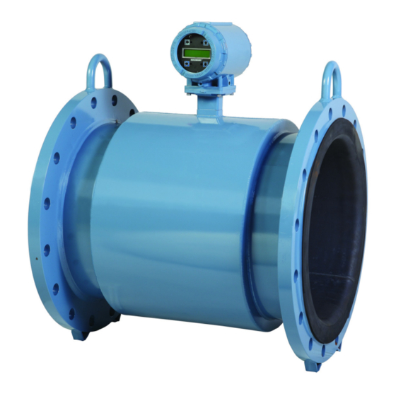
Emerson Rosemount 8750W Quick Start Manual
Magnetic flowmeter system for utility, water, and wastewater applications
Hide thumbs
Also See for Rosemount 8750W:
- Reference manual (264 pages) ,
- Reference manual (214 pages) ,
- Reference manual (192 pages)
Table of Contents
Quick Links
See also:
Reference Manual
Table of Contents

Related Manuals for Emerson Rosemount 8750W


Summary of Contents for Emerson Rosemount 8750W
- Page 1 Quick Start Guide 00825-0300-4750, Rev CA March 2016 Rosemount 8750W ™ Magnetic Flowmeter System for Utility, Water, and Wastewater Applications...
-
Page 2: Table Of Contents
To prevent ignition of flammable or combustible atmospheres, disconnect power before servicing circuits. Do not connect a Rosemount 8750W Transmitter to a non-Rosemount sensor that is located in an explosive atmosphere. Follow national, local, and plant standards to properly earth ground the transmitter and sensor. The earth ground must be separate from the process reference ground. -
Page 3: Transmitter Installation
Consider mechanical, electrical, and environmental requirements. 1.1 Identify options and configurations The typical installation of the Rosemount 8750W includes a device power connection, a 4 20mA output connection, and sensor coil and electrode – connections. Other applications may require one or more of the following... - Page 4 Quick Start Guide 1.2 Mechanical considerations The mounting site for the Rosemount 8750W should provide enough room for secure mounting, easy access to conduit entries, full opening of the transmitter covers, and easy readability of the LOI screen if equipped.
- Page 5 (71,4) (78,0) (56,4) 1.80 (45,7) 5.00 (127,0) 10.18 (258,6) -in. 14 NPT conduit entry – B. LOI cover C. 2-in. pipe bracket D. Ground lug Dimensions are in inches (millimeters). Figure 2. Rosemount 8750W Integral Field Mount Transmitter 5.82 (147,8)
- Page 6 March 2016 Quick Start Guide Figure 3. Rosemount 8750W Wall Mount Transmitter with Standard Cover 9.01 4.31 (229) (109) 3.11 2.81 0.44 (79) (71) 12.02 (305) 11.15 (283) 2.96 (75) A. Ground lug -in. 14 NPT or M20 conduit entry –...
-
Page 7: Environmental Considerations
Quick Start Guide March 2016 1.3 Electrical considerations Before making any electrical connections to the Rosemount 8750W, consider national, local and plant electrical installation requirements. Be sure to have the proper power supply, conduit, and other accessories necessary to comply with these standards. -
Page 8: Handling And Lifting
March 2016 Quick Start Guide 2.0 Handling and lifting Handle all parts carefully to prevent damage. Whenever possible, transport the system to the installation site in the original shipping container. PTFE-lined sensors are shipped with end covers that protect it from both ... -
Page 9: Mounting
Quick Start Guide March 2016 3.0 Mounting 3.1 Upstream/downstream piping To ensure specified accuracy over widely varying process conditions, install the sensor with a minimum of five straight pipe diameters upstream and two pipe diameters downstream from the electrode plane (see Figure Figure 6. - Page 10 March 2016 Quick Start Guide Figure 8. Sensor Orientation 3.4 Electrode orientation The electrodes in the sensor are properly oriented when the two measurement electrodes are in the 3 and 9 o’clock positions or within 45° from the horizontal, as shown on the left of Figure 9.
-
Page 11: Sensor Installation
Quick Start Guide March 2016 4.0 Sensor installation 4.1 Gaskets The sensor requires a gasket at each process connection. The gasket material must be compatible with the process fluid and operating conditions. Gaskets are required on each side of a grounding ring (see Figure 10). - Page 12 EN flanges for line sizes 30-in. (750 mm) to 48-in. (1300 mm). Consult your ™ local Emerson Process Management representative if the flange rating of the sensor is not listed. Tighten flange bolts on the upstream side of the sensor in the...
- Page 13 Quick Start Guide March 2016 Table 3. Lining Material Fluoropolymer liners Resilient liners P - Polyurethane T - PTFE N - Neoprene Table 4. Flange Bolt Torque and Load Specifications for 8750W (ASME) Fluoropolymer liners Resilient liners Size Line size Class 150 Class 300 Class 150...
- Page 14 March 2016 Quick Start Guide Table 5. Flange Bolt Torque and Load Specifications for 8750W (EN 1092-1) Fluoropolymer liners Size Line size PN10 PN 16 PN 25 PN 40 code (Newton-meter) (Newton-meter) (Newton-meter) (Newton-meter) 0.5-in. (15 mm) 1-in. (25 mm) 1.5-in.
- Page 15 Quick Start Guide March 2016 Table 6. Flange Bolt Torque and Load Specifications for Rosemount 8750W Larger Line Sizes (AWWA C207) Fluoropolymer liners Size Line size code Class D Class E Class F (pound-feet) (pound-feet) (pound-feet) 30-in. (750 mm) 36-in. (900 mm) Resilient liners 30-in.
-
Page 16: Process Reference Connection
March 2016 Quick Start Guide 5.0 Process reference connection Figure 12 through Figure 15 illustrate process reference connections only. Earth safety ground is also required as part of the installation but is not shown in the figures. Follow national, local, and plant electrical codes for safety ground. Table 8 to determine which process reference option to follow for proper installation. - Page 17 Quick Start Guide March 2016 Figure 13. Grounding with Grounding Rings in Conductive Pipe A. Grounding rings Figure 14. Grounding with Grounding Rings in Non-conductive Pipe A. Grounding rings Figure 15. Grounding with Reference Electrode in Conductive Unlined Pipe...
-
Page 18: Wiring The Transmitter
March 2016 Quick Start Guide Figure 16. Grounding for Line Sizes 10-in. and Larger 6.0 Wiring the transmitter This wiring section covers the wiring between the transmitter and sensor, the 20mA output, and supplying power to the transmitter. Follow the conduit –... - Page 19 (see Figure 18). Use only the interconnecting cable provided by Emerson Process Management. For replacement transmitters use the existing interconnecting cable from the original assembly. Replacement cables are available. Figure 18. Interconnecting Cables...
- Page 20 March 2016 Quick Start Guide Table 9. Component Cable Kits ° ° Standard temperature (-20 C to 75 Cable kit number Description Individual cable Alpha p/n Kit, component cables, std temp. Coil 08732-0065-0001 518243 (includes coil + electrode) Electrode (feet) 518245 Kit, component cables, std temp.
- Page 21 Figure 19. Cable lengths should be limited to less than 500-feet (152 m). Consult your local Emerson representative for length between 500–1000-feet (152-304 m). Equal length cable is required for each. For installations using the combination coil drive/electrode cable, Figure 20.
- Page 22 Potential shock hazard across remote junction box terminals 1 and 2 (40V). Explosion Hazard Electrodes exposed to process. Use only compatible transmitter and approved installation practices. Figure 22. Remote Junction Box Views A. Sensor For complete sensor wiring diagrams, reference Installation Drawing Rosemount 8750W-1052.
- Page 23 Quick Start Guide March 2016 6.4 Transmitter terminal block connections Field mount transmitter Remove the back cover of the transmitter to access the terminal block. Figure 23 for terminal identification. To connect pulse output and/or discrete input/output consult the comprehensive product manual. Figure 23.
-
Page 24: Analog Output
March 2016 Quick Start Guide 6.5 Analog output Field mount transmitter The analog output signal is a 4–20mA current loop. The loop can be powered internally or externally via a hardware switch located on the front of the electronics stack. The switch is set to internal power when shipped from the factory. - Page 25 Quick Start Guide March 2016 Figure 26. Field Mount Transmitter Analog Wiring - External Power A. Power supply Analog loop load limitations Maximum loop resistance is determined by the voltage level of the external power supply, as described in Figure Figure 27.
- Page 26 12 42VDC. Before connecting power to the – Rosemount 8750W, be sure to have the proper power supply, conduit, and other accessories. Wire the transmitter according to national, local, and plant electrical requirements for the supply voltage.
- Page 27 Quick Start Guide March 2016 Figure 30. Field Mount Transmitter DC Power Requirements Power supply (VDC) Peak inrush is 42A at 42VDC supply, lasting approximately 1ms. Inrush for other supply voltages can be estimated with: Inrush (Amps) = Supply (Volts)/1.0 Figure 31.
- Page 28 March 2016 Quick Start Guide Figure 32. Field Mount Transmitter AC Power Requirements Power supply (VAC) Power supply (VAC) Peak inrush is 35.7A at 250VAC supply, lasting approximately 1ms. Inrush for other supply voltages can be estimated with: Inrush (Amps) = Supply (Volts)/7.0...
- Page 29 Quick Start Guide March 2016 Figure 33. Wall Mount Transmitter AC Power Requirements Power supply (VAC) Power supply (VAC)
- Page 30 Connect the device through an external disconnect or circuit breaker per national and local electrical code. Installation category The installation category for the Rosemount 8750W is OVERVOLTAGE CAT II. Overcurrent protection The Rosemount 8750W Transmitter requires overcurrent protection of the supply lines.
-
Page 31: Basic Configuration
Quick Start Guide March 2016 Wall mount transmitter power terminals Figure 24 for wall mount transmitter terminal connections. For AC powered transmitter (90 250VAC, 50/60 Hz) – Connect AC Neutral to terminal N and AC Line to terminal L1. For DC powered transmitter Connect DC- to terminal N and DC+ to terminal L1. - Page 32 March 2016 Quick Start Guide URV (upper range value) The URV sets the 20 mA point for the analog output. This value is typically set to full-scale flow. The units that appear will be the same as those selected under the flow units parameter.
- Page 33 Quick Start Guide March 2016 7.2 Calibration number The sensor calibration number is a 16-digit number generated at the Rosemount factory during flow calibration and is unique to each sensor and is located in the sensor tag. Table 13. Handheld Fast Keys (Field Communicator) Function HART fast keys Process variables...
- Page 34 March 2016 Quick Start Guide Figure 34. Field Mount Transmitter Local Operator Interface (LOI) Menu Tree...
- Page 35 Quick Start Guide March 2016 Figure 35. Wall Mount Transmitter Local Operator Interface (LOI) Menu Tree...
-
Page 36: Product Certifications
March 2016 Quick Start Guide 8.0 Product Certifications Table 14. Rosemount 8750W Platform Order Platform rating Region Agency Certification number code USA, FM or CSA 3030548(FM) or Ordinary Locations Canada and EAC 70030489(CSA) EU, CU ATEX Non-Sparking and Dust for... - Page 37 Quick Start Guide March 2016 Table 15. Approval Markings and Logos Marking or Meaning of marking or symbol Symbol Region symbol name Compliance with all applicable European Union European Union Directives. Compliance with Equipment and Protective systems intended for use in Potentially Explosive ATEX European Union Atmospheres directive (ATEX) (94/9/EC).
- Page 38 Categories II - III assessed for conformity per module H procedures. QS Certificate of Assessment EC No. 4741-2014-CE-HOU-DNV: Module H Conformity Assessment Rosemount 8750W Flanged Flowtubes Line size 40 mm to 600 mm (1 -in to 24-in) EN 1092-1 flanges and ASME B16.5 class 150 and ASME B16.5 Class 300 flanges.
- Page 39 FM Approvals, a nationally recognized testing laboratory (NRTL) as accredited by the Federal Occupational Safety and Health Administration (OSHA). Rosemount 8750W Magnetic Flowtube and Transmitter All Flowtubes and Integral or Remote Mount Transmitters (Transmitter mount codes T or R) Non-Incendive for Class I, Division 2, Groups ABCD: T4 Dust-Ignition Proof for Class II/III, Division 1, Groups EFG: T5 -29 °C ≤...
- Page 40 March 2016 Quick Start Guide The transmitter is rated IP66 when integral or remote mounted, it is not IP68 nor IP69K rated. The IP68 rating only applies to the flowtube and the remote junction box when the transmitter is remotely mounted. The IP68 rating is only valid at a depth of 10 meters for 48 hours.
- Page 41 Quick Start Guide March 2016 Figure 36. Rosemount 8750W Declaration of Conformity...
- Page 42 March 2016 Quick Start Guide...
- Page 43 Quick Start Guide March 2016...
- Page 44 March 2016 Quick Start Guide 8.3 IEC EX & ATEX 1. Equipment markings: a. Type Examination Certificate (ATEX): DEKRA 15ATEX0003 X b. Certificate of Conformity (IECEx): IECEx DEK 15.0001X 2. Required documentation: a. 8750W-2052 Installation Drawing Model 8750W ATEX/IECEx Hazardous (Ex) Locations 3.
- Page 45 March 2016 d. Electrical parameters, maximum surface temperatures and other limit values. Electrical 1. See document 8750W-2052 Rosemount 8750W Flow Transmitter 90 - 250 VAC, 0.45 A, 40 VA Power input 12 - 42 VDC, 1.2 A, 15 W Internally powered (Active): outputs up to 12 VDC, 12.1 mA, 73 mW...
- Page 46 March 2016 Quick Start Guide g. Supply wire requirements; Use 10–18 AWG wire rated for the proper temperature of the application. For wire 10–14 AWG use lugs or other appropriate connectors. For connections in ambient temperatures above 122 °F (50 °C), use a wire rated for 194 °F (90 °C). h.
- Page 47 Quick Start Guide March 2016 Table 16. Nomenclature Magnetic Flow Meter System Model Rosemount 8750W and Electrical Data 8750W … … 005 … … M4 … AX … … RH50 VIII Designation Explanation Value Explanation Model 8750W Flow Meter System Model 8750W...
-
Page 48: Installation And Wiring Drawings
March 2016 Quick Start Guide 9.0 Installation and wiring drawings... - Page 49 Quick Start Guide March 2016...
- Page 50 March 2016 Quick Start Guide...
- Page 51 Quick Start Guide March 2016...
- Page 52 [email protected] Standard Terms and Conditions of Sale can be found at Middle East and Africa Regional Office Emerson.com/en-us/pages/Terms-of-Use.aspx The Emerson logo is a trademark and service mark of Emerson Emerson Process Management Electric Co. Emerson FZE P.O. Box 17033, Rosemount and Rosemount logotype are trademarks of Emerson...