Table of Contents
Quick Links
Chapters
Table of Contents

Related Manuals for Omron fq2


Summary of Contents for Omron fq2
- Page 1 Smart Camera User's Manual Cat. No. Z326-E1-01A...
- Page 2 FQ2. When using the FQ2, be sure to observe the following: • The FQ2 must be operated by personnel knowledgeable in electrical engineering. • To ensure correct use, please read this manual thoroughly to deepen your understanding of the product.
-
Page 3: Introduction
APPLICATION CONSIDERATIONS (Please Read) Introduction User's Manual Installation and Connections Taking Images Setting Up Inspections Testing and Saving Settings Operation Convenient Functions Controlling Operation and Outputting Data with a Parallel Connection Connecting through Ethernet Connecting with RS-232C Troubleshooting Appendices Smart Camera... - Page 4 LOSS OF PROFITS OR COMMERCIAL LOSS IN ANY WAY CONNECTED WITH THE PRODUCTS, WHETHER SUCH CLAIM IS BASED ON CONTRACT, WARRANTY, NEGLIGENCE, OR STRICT LIABILITY. In no event shall responsibility of OMRON for any act exceed the individual price of the product on which liability is asserted.
- Page 5 Performance data given in this document is provided as a guide for the user in determining suitability and does not constitute a warranty. It may represent the result of OMRON’s test conditions, and the users must correlate it to actual application requirements. Actual performance is subject to the OMRON Warranty and Limitations of Liability.
-
Page 6: Meanings Of Signal Words
Dispose of the Touch Finder as industrial waste, and never disassemble, apply pressure that would deform, heat to 100 °C or higher, or incinerate the Touch Finder. High-voltage parts inside; danger of electrical shock. Do not open the product cover. FQ2 User’s Manual... -
Page 7: Precautions For Safe Use
Battery may result in the Battery heating, smoking, rupturing, or igniting. • If the Touch Finder (FQ2-D31) will be installed permanently or semi-permanently, remove the Battery (FQ- BAT1). If the rated temperature is exceeded with the Battery inserted, the protective circuit may activate and stop the Touch Finder. - Page 8 • Do not drop or subject the products to shock. • Use the special Sensor (FQ2-S), Touch Finder (FQ2-D), Sensor Data Unit (FQ-SDU), Cables (FQ-WN, FQ- WD, FQ-WU, and FQ-VP), Battery (FQ-BAT1), and AC Adapter (FQ-AC). Using other than the specified products may cause fire, burning, malfunction or failure.
-
Page 9: Precautions For Correct Use
• For cables, use only the special products specified in this manual. p.487, p.488, p.489, p.490 • Use only combinations of the Sensor and Touch Finder specified in this manual. Using other combinations may cause malfunction or damage. FQ2 User’s Manual... - Page 10 PC are indicated enclosed by brackets "[ ]". ■ Visual Aids Indicates points that are important to achieve the full product performance, Important such as operational precautions. Indicates application procedures. Note Indicates pages where related information can be found. FQ2 User’s Manual...
-
Page 11: Table Of Contents
1-1 FQ2-series Vision Sensors........ - Page 12 Errors ............104 FQ2 User’s Manual...
- Page 13 Errors ............130 FQ2 User’s Manual...
- Page 14 Errors ............154 FQ2 User’s Manual...
- Page 15 Setting the Startup Scene ........192 FQ2 User’s Manual...
- Page 16 Making Settings with Stored Images ....... . 227 FQ2 User’s Manual...
- Page 17 9-1 Introduction ..........282 FQ2 User’s Manual...
- Page 18 Introduction to EtherNet/IP ........283 FQ2 Communications for EtherNet/IP Connections ....285 Setting Up EtherNet/IP Communications .
- Page 19 FQ2-S Sensor ........
- Page 20 Revision History ..........512 FQ2 User’s Manual...
- Page 21 Introduction 1-1 FQ2-series Vision Sensors ........20 1-2 Measurement Process .
-
Page 22: Fq2-Series Vision Sensors
1-1 FQ2-series Vision Sensors The FQ2 Series features Vision Sensors with integrated cameras and controllers. They can be used to easily achieve simple inspections and measurements. You can use parallel controls, no-protocol communications on Ethernet, PLC Link communications on Ethernet, and EtherNet/IP communications on Ethernet as standard features. -
Page 23: Measurement Process
• The overall judgement of all inspection items are output using OR logic. • You can output detailed measurement result from the inspection items. Output • Measurement data and image data can be logged in memory in the Sensor or in an SD card. Logging FQ2 User’s Manual Measurement Process... -
Page 24: Startup Display And Display Elements
When the Touch Finder is started, IP addresses are automatically set for each Sensor. To allocate specific IP addresses, set the IP address of each Sensor and the Touch Finder. Setting Up Ethernet: p. 53 Startup Display and Display Elements FQ2 User’s Manual... -
Page 25: Display Elements
• Camera image file: An image that was saved in external memory with (Log Image Button) is displayed. Run Mode In Run Mode, measurements are performed, and measurement results are output. p. 179 FQ2 User’s Manual Startup Display and Display Elements... -
Page 26: Testing And Saving Settings
1-4 Basic Operational Flow The following flow shows the basic operation of FQ2-series Vision Sensors. Section 2 Installation and Connections and Wiring Connections Section 1 Starting the Sensor 1-3 Startup Display and Display Elements Image Setup Section 3 Taking Images... - Page 27 Installation and Connections 2-1 System Configuration ........26 2-2 Part Names and Functions .
-
Page 28: System Configuration
Cable (RJ45/M12) for FQ-SDU2 24-V power supply Trigger sensor Sensor control PLC I/O control PLC Connecting More Than One Sensors 24-V power supply FQ2 Vision Sensors (8 max.) FL-STC FL-series Setup Tool Lighting Controller External Lighting Touch Finder or PC Tool... - Page 29 W4S1-0@@ Used to connect multiple Sensors to one Touch Finder or PC Tool. Sensor Data Unit FQ-WU0@@ This cable connects the FQ2-S3 Sensor to the Sensor Data Unit. cable Parallel cable for FQ-VP1@@@ This cable connects the Parallel Interface Sensor Data Unit to an external device.
- Page 30 Connection Compatibility Yes: Supported, No: Not supported Type of connection to FQ2-S Other connection EtherNet/IP PLC Link on TCP no-pro- FINS/TCP RS-232C Parallel communications Ethernet tocol commu- no-protocol Sensor’s Parallel Inter- nications on communica- standard par- face Ethernet tions on...
-
Page 31: Part Names And Functions
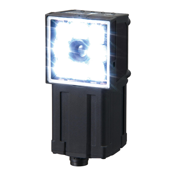
2-2 Part Names and Functions FQ2-S@@@@@@-@@@ (Sensors with Built-in Lighting) Name Description Lighting LEDs for illumination Camera lens This lens can be focused. I/O Cable connector An FQ-WD or FQ-WU I/O Cable is used to connect the Sensor to the power supply and external I/O. - Page 32 FQ2-S3@-@@@ (Sensors with C-mounts) Bottom Sensor Mounted to Base Name Description C-mount lens mounting surface The C-mount lens and macro ring are attached here. Determine the appro- priate CCTV lens (C-mount lens) to use based on the field of view required for the size of the measurement object.
-
Page 33: Touch Finder
Insert the connector until it locks in place. (11) Strap holder This is a holder for attaching the strap. (12) AC power supply connector Used to connect the AC adapter. *1: Applicable to the FQ2-D31 only. FQ2 User’s Manual Part Names and Functions... -
Page 34: Sensor Data Units
Sensor Data Unit Sensor Data Unit Sensor Data Unit Name Description Sensor connector Connects to the FQ2-S3. Power supply and ground termi- Connects to the 24-V power source and the ground line. nal block Parallel I/O connector Connects to the I/O connector. -
Page 35: Installation
2-3 Installation Installing the Sensor FQ2-S@@@@@@ (Sensors with Built-in Lighting) Installation Procedure Align the tabs on one side of the Mounting Bracket with the slot on the Sensor. Mounting The FQ-XL Mounting Bracket can be attached to the back, Bracket side, or front of the Sensor. -
Page 36: Fq2-S3@-@@@ (Sensors With C-Mounts)
Insert a flat-blade screwdriver between the Mounting Brack- et and the Sensor case on either side and remove the Mounting Bracket. Mounting Bracket FQ2-S3@-@@@ (Sensors with C-mounts) Installation Procedure Directly Mounting the Sensor Mount the Sensor with M3 screws. Tightening torque: 0.54 N·m... -
Page 37: Lens Selection
SV-1614V 1000 SV-2514V SV-3518V t0.5 SV-5018V t0.5 SV-7527V t0.5 SV-10035V t0.5 t: Macro ring Examples t0: Macro ring is not required. t5: A 5-mm macro ring is required. 1000 Y axis of field of view (mm) FQ2 User’s Manual Installation... - Page 38 200 mm and a 2-mm macro ring is required. Camera Macro ring t@ (mm) Camera lens Camera installation distance (mm) Measurement object Field of view (mm) Lens Models and Dimensions Maximum outside diameter 1-32 UNF Filter threads (C-mount threads) Total length Installation FQ2 User’s Manual...
- Page 39 33.5 mm M27 P0.5 3Z4S-LE SV-5018V 47.97 mm F1.8 32 mm 37.0 mm M30.5 P0.5 3Z4S-LE SV-7527V 76.71 mm F2.7 32 mm 42.0 mm M30.5 P0.5 3Z4S-LE SV-10035V 95.4 mm F3.5 32 mm 43.9 mm M30.5 P0.5 FQ2 User’s Manual Installation...
-
Page 40: Installation Precautions
• To prevent interference by noise, do not mount the Sensor on panels which contain high-voltage devices. • To keep the level of noise from the surrounding environment to a minimum, install the Sensor and Touch Finder at least 10 m away from power lines. Installation FQ2 User’s Manual... -
Page 41: Mounting To Din Track
• Always turn OFF the Touch Finder power before attaching or detaching the Panel Mount Adapter. Attaching or detaching with the power turned ON may cause a failure. Set the Touch Finder in the Panel Mount Adapter. FQ2 User’s Manual Installation... -
Page 42: Using The Touch Finder As A Portable Device (With Battery)
There are two types of straps (FQ-XH, sold separately), a Neck Strap and a Hand Strap. Neck Strap Hand Strap Attach the Mini-strap to the Touch Finder. There are a total of four holes for attaching the Mini-strap on the left and on the right of the Touch Finder. Installation FQ2 User’s Manual... -
Page 43: Mounting To Din Track
• Always hook the clip at the top of the Sensor Data Unit on the DIN Track first. If the lower clip is hooked on first, the Touch Finder will not be mounted very securely. Removal Procedure Pull down on the slider on the Sensor Data Unit. Lift the Sensor Data Unit at the bottom and remove it from the DIN Track. FQ2 User’s Manual Installation... -
Page 44: Wiring
2-4 Wiring Wiring the Sensor Connect the I/O Cable to the I/O Cable connector located at the bottom of the Sensor. FQ2-S@@@@@@ (Sensors with Built-in Lighting or Sensors with C-mounts) Brown Power supply Blue Black OUT0 (OR) Orange OUT1 (BUSY) -
Page 45: I/O Signal Circuit Diagrams
Attach the enclosed LED warning label to the cable or other location. The LED warning label must be attached to a location that is readily visible from the Sensor. Attachment Example Warning Label Warning Label 12-6 LED Safety: p. 497 FQ2 User’s Manual Wiring... - Page 46 Tightening torque: 0.54 N·m) Frame ground For the I/O connector harness, use an FQ-VP1@@@ Parallel Cable for the FQ-SDU1 or a MIL-standard harness, such as the OMRON XZ2F. (The Cables are sold separately.) Signal Application Power supply (24 V) These terminals are for the external power supply (24 V).
- Page 47 Trigger delay Imaging element Shutter time shutter signal SHTOUT 10 ms The SHTOUT signal turns ON for approximately 10 ms (fixed) when the shutter time (exposure period) elapses after the trigger is input from an external device. FQ2 User’s Manual Wiring...
- Page 48 RS-232C connector 0.54 N·m) Frame ground For the I/O connector harness, use an FQ-VP2@@@ Parallel Cable for the FQ-SDU2 or a MIL-standard harness, such as the OMRON XZ2F. (The Cables are sold separately.) Signal Application Power supply (24 V) These terminals are for the external power supply (24 V).
- Page 49 Pin numbers will depend on the external device being connected. Refer to the manual for the personal computer or PLC being connected. Use a compatible connector. • Recommended items Manufacturer Model Socket OMRON Corporation XM3D-0921 Hood OMRON Corporation XM2S-0913 FQ2 User’s Manual Wiring...
- Page 50 Align the connector with the socket and press it straight into place, then fix it with the screws on both sides of the connector. Important Turn OFF the power supply before connecting or disconnecting a Cable. Peripheral devices may be damaged if the cable is connected or disconnected with the power ON. Wiring FQ2 User’s Manual...
- Page 51 Supply power from a DC power supply for which measures have been applied to prevent high voltages (e.g., a safety extra-low-voltage circuit). If UL certification is required for the overall system, use a UL Class II DC power supply. FQ2 User’s Manual Wiring...
- Page 52 If UL certification is required for the overall system, use a UL Class II DC power supply. • When using the FQ-D31, do not connect a switching regulator and AC Adapter (FQ-AC@) at the same time. Wiring FQ2 User’s Manual...
-
Page 53: Charging The Battery
The CHARGE indicator will be lit while the battery is being charged. It will go out when charging the battery has been com- pleted. Note The Touch Finder will operate even if the AC adapter is connected when no battery is mounted in the Touch Finder. FQ2 User’s Manual Wiring... - Page 54 Li-ion00 • California regulations concerning perchlorate: This product is a lithium battery that contains perchlorate, which is regulated by the State of California. Please com- ply with these regulations. For details see the following URL: www.dtsc.ca.gov/hazardouswaste/perchlorate/ Wiring FQ2 User’s Manual...
-
Page 55: Setting Up Ethernet
● Using a DHCP Server • Sensor (Setup Mode) − [Sensor settings] − [Network] − [Ethernet] − [IP address setting] Press [DHCP]. • Touch Finder (Setup Mode) − [TF settings] − [Ethernet]] − [IP address setting] Press [DHCP]. FQ2 User’s Manual Setting Up Ethernet... -
Page 56: Connecting To Sensors From External Devices Such As Plcs
Set the IP address and subnet mask according to the network where the external devices, such as PLCs, are connected. Note If you connect OMRON CS/CJ-series PLCs to the Ethernet, the following default IP addresses are assigned to the PLCs. • IP address: 192.168.250.node_address... - Page 57 • If you connect the PC Tool to a Sensor on a different network through a router, set fixed IP addresses. • If you use an EtherNet/IP connections, set fixed IP address for the Sensors. FQ2 User’s Manual Setting Up Ethernet...
- Page 58 MEMO Setting Up Ethernet FQ2 User’s Manual...
- Page 59 Taking Images 3-1 Selecting a Sensor for Configuration......58 3-2 Setting Conditions for Taking Images ......59 3-3 Adjusting Image Quality .
-
Page 60: Selecting A Sensor For Configuration
There are different methods that you can use to connect the Sensors. For example, you can automatically connect to the Sensors that are recognized by the Touch Finder, or you can manually register the Sensors to connect. 7-5 Connecting to More Than One Sensor: p. 204 Selecting a Sensor for Configuration FQ2 User’s Manual... -
Page 61: Setting Conditions For Taking Images
Apply filters to adjust the images that were taken. p. 74 Compensating for Position Offset (Position Compensation Items) Recognize measurement objects that are not in a consistent location and move them to the center of the image. FQ2 User’s Manual Setting Conditions for Taking Images... -
Page 62: Adjusting Image Quality
Do not force the screw if it does not rotate anymore. This will damage the Sensor. • Do not turn the focus adjustment screw with a force that is greater than 0.1 N·m. This may damage it. Adjusting Image Quality FQ2 User’s Manual... -
Page 63: Adjusting Image Brightness With External Lighting
If the Sensor is used on a high-speed line, check that the images are not blurred under actual operating conditions. Brightness Correction Mode (FQ2-S1@@@@@@/FQ2-S2@@@@@) If the brightness changes inconsistently with each image, turn ON the Brightness Correction Mode. - Page 64 If the shutter speed is fast, the image 1/1 to 1/60,000 will be dark. 1/250 to 1/60,000 (for Cameras with Built-in Lighting) For FQ2-S1 or FQ2-S2 1/1 to 1/50,000 1/250 to 1/50,000 (for Cameras with Built-in Lighting) Default: 1/250 Adjusting Image Quality FQ2 User’s Manual...
-
Page 65: Taking Clear Images Of Moving Objects
Important • To ensure stable operation when the FQ2-S1 or FQ2-S2 is connected, we recommend that you set the gain to 16. • If the recommended value is exceeded, the brightness will not be stable and measurement values may be inconsistent. -
Page 66: Improving The Image Quality Of Metallic And Other Shiny Surfaces
Set the best level for the HDR Mode. As shown below, the higher the level, the wider the combined dy- namic range will be. Level 1 Level 2 Level 3 Level 4 Dark Bright Adjusting Image Quality FQ2 User’s Manual... - Page 67 ] – [White balance] on the right side of the display. Press the [Auto] Button. The Sensor will automatical- ly adjust the colors. Move the bar to the left (light) or right (dark) to fine- tune the colors. Press [OK]. FQ2 User’s Manual Adjusting Image Quality...
-
Page 68: Adjusting The Timing Of Taking Images
Press [OK]. Note The delay time can be set using the adjustment bar or by directly entering a value. Move the bar to the left or right. Directly input the delay time. Adjusting the Timing of Taking Images FQ2 User’s Manual... -
Page 69: Adjusting External Lighting Timing
The delay time for preventing mutual interference must be longer than the shutter time. When the lighting built into the Sensor is used, the shutter time is 4 ms max. Therefore make the delay at least 4 ms. FQ2 User’s Manual Adjusting the Timing of Taking Images... -
Page 70: Adjusting The Images That Were Taken
Source image: Previous image [Prev.] adjustment 2: Search Position Compensation (position compensation item) Processed image (processes 0, 1, Source image: Previous image [Prev.] and 2) Measurements are performed with inspection items. Adjusting the Images That Were Taken FQ2 User’s Manual... -
Page 71: Filtering The Images (Filter Items)
Extracts horizontal edges between light and dark in the image. (extract horizontal edges) Extract vertical edges Extracts vertical edges between light and dark in the image. Enhance edges Enhances image edges between light and dark. FQ2 User’s Manual Adjusting the Images That Were Taken... - Page 72 The filter is applied to the image that is taken by the Camera. Prev. (previous image) The filter is applied to the image that resulted from the previous filter items or posi- tion compensation items in the processing order. Adjusting the Images That Were Taken FQ2 User’s Manual...
- Page 73 Select the type of color filter to use. If you select [Custom filter], set the gains for red, green, and blue. • HSV Set the following ranges: [Std. Hue], [Hue range], and [Chroma]. Press [OK]. Press [Back]. FQ2 User’s Manual Adjusting the Images That Were Taken...
- Page 74 Lower limit Upper limit Input value You can use either of the following methods to set the upper and lower limits of the brightness range to extract with the Background Suppression item. Adjusting the Images That Were Taken FQ2 User’s Manual...
- Page 75 Set the upper and lower limit values of the brightness range. (for Sensors with Monochrome Cameras (or after a Color Gray Filter)) Press [Back]. Press [OK]. Press [Back]. FQ2 User’s Manual Adjusting the Images That Were Taken...
-
Page 76: Compensating For Position Offset (Position Compensation Items)
• Edge position comp. (Edge Position Compensation) • 2Edge position comp. (Two-edge Position Compensation) • 2Edge midpoint comp. (Two-edge Midpoint Compensation) • Edge rot. pos. comp. (Edge Rotation Position Compensation) Adjusting the Images That Were Taken FQ2 User’s Manual... - Page 77 If you apply the results of position compensation to the Camera image, only the position information from position compensation is applied to the image to be measured. Using Filter Items for Processing with Position Compensation Items: p. 76 FQ2 User’s Manual Adjusting the Images That Were Taken...
- Page 78 Search Position If the source image is set to the camera image. Compensation the results of position compensation are applied to the item Camera image. Measurements are performed with inspection items. Adjusting the Images That Were Taken FQ2 User’s Manual...
- Page 79 You can select the image to which to apply the results of position compensation processing. Applying the Results of Position Compensation: p. 75 • Interpolation You can select the precision of position compensation. FQ2 User’s Manual Adjusting the Images That Were Taken...
-
Page 80: Search Position Compensation
Note To perform position compensation for a rotated image pattern, use the Shape Search Position Compensation item. [Image] − [Image adjustment] Press an unused number and then press [Add pos. comp.]. Adjusting the Images That Were Taken FQ2 User’s Manual... - Page 81 −99,999.9999 to 99,999.9999 Reference Y This is the Y coordinate of the position where the model was registered. Correlation This is the correlation. 0 to 100 FQ2 User’s Manual Adjusting the Images That Were Taken...
- Page 82 [Image] − [Image adjustment] − [Edge position comp.] − [Modify] − [Details] - [Scroll parameter] − [Interpolation] The settings are the same as those for the Shape Search Position Compensation item. Interpolation: p. 77 Adjusting the Images That Were Taken FQ2 User’s Manual...
- Page 83 Press an unused number and then press [Add pos. comp.]. − Press [Edge] [2Edge position comp.] Make any detailed settings as required for the position compensation processing. Refer to Detailed Settings for Search Position Compensation, below. Press [OK]. Press [Back]. FQ2 User’s Manual Adjusting the Images That Were Taken...
- Page 84 • Measurement Data That Can Be Used for External Outputs and Calculations The following values can be used as measurement data and output to external devices via Ethernet or used in calculations. Adjusting the Images That Were Taken FQ2 User’s Manual...
- Page 85 0 direction for edge 1 Color of edge to be found [Image] − [Image adjustment] Press an unused number and then press [Add pos. comp.]. FQ2 User’s Manual Adjusting the Images That Were Taken...
- Page 86 This is the amount of position com- pensation for the Y coordinate. −99,999.9999 to 99,999.9999 Edge 0 position X This is the X coordinate of the mea- sured edge 0 position. Adjusting the Images That Were Taken FQ2 User’s Manual...
-
Page 87: Edge Rotation Position Compensation
Press an unused number and then press [Add pos. comp.]. − Press [Edge] [Edge rot. pos. Comp.] Make any detailed settings as required for the position compensation processing. Refer to Detailed Settings for Edge Rotation Position Compensation, below. FQ2 User’s Manual Adjusting the Images That Were Taken... - Page 88 Scroll θ −180 to 180 This is the amount of position compensa- tion. −99,999.9999 to 99,999.9999 Edge 0 position X This is the X coordinate of the measured edge 0 position. Adjusting the Images That Were Taken FQ2 User’s Manual...
- Page 89 This is the Y coordinate of the edge 1 1 reference position position when it was registered. −180 to 180 Reference angle This is the angle when the edge was reg- istered. FQ2 User’s Manual Adjusting the Images That Were Taken...
- Page 90 MEMO Adjusting the Images That Were Taken FQ2 User’s Manual...
- Page 91 Setting Up Inspections 4-1 Inspection Item Selection Guide......90 4-2 Setup Procedure for Inspection Items ......92 4-3 Configuring Inspection Items .
-
Page 92: Inspection Item Selection Guide
4-1 Inspection Item Selection Guide The FQ2 Vision Sensor uses inspection items to judge measurement objects. There are eight different measurement objects. Select the best inspection items for the characteristics of the measurement object that are being judged. Inspection Example... - Page 93 Detecting parts Color Data p. 136 Judging according to sizes Judging if there is silver paste Area p. 140 Judging according to shapes and quantities Judging the number of labels Labeling p. 146 FQ2 User’s Manual Inspection Item Selection Guide...
-
Page 94: Setup Procedure For Inspection Items
Setting Detailed Items Step 4 Re-teaching Step 5 Note Only one inspection item can be used with the FQ2-S1@. Up to 32 inspection items can be combined and used with the FQ2-S2@ or FQ2-S3@. Setup Procedure for Inspection Items FQ2 User’s Manual... -
Page 95: Configuring Inspection Items
1.--- and set it in the same way. Note If more than six inspection items are set, drag the icon at the bottom of the menu upward to display the next inspection item numbers. FQ2 User’s Manual Configuring Inspection Items... -
Page 96: Modifying Existing Inspection Items
Press the number of the inspection item to be delet- Press [Delete] on the menu. Note Executing Similar Measurements in Different Places → Copy an inspection item that is already registered: [Copy]. → Change the name of an inspection item: [Rename]. Configuring Inspection Items FQ2 User’s Manual... -
Page 97: Inspecting With The Search Inspection Item
Press an unused inspection item number and press [Add item.]. Press [Search]. Registering inspection items: p. 93 Note Drag the arrow at the bottom of the menu upward to display all of the inspection items. FQ2 User’s Manual Inspecting with the Search Inspection Item... - Page 98 Defaults: Lower limit: −180, Upper limit: 180 Count Range: 0 to 32 Adjust the upper and lower limits of the detection count for an OK Defaults: Lower limit: 0, Upper limit: 32 judgement. Inspecting with the Search Inspection Item FQ2 User’s Manual...
-
Page 99: Increasing Measurement Position Accuracy
Sorts the results in order from the smallest measure- ment Y position to the largest. Pos.Y descending order (descending order of position Y) Sorts the results in order from the largest measure- ment Y position to the smallest. FQ2 User’s Manual Inspecting with the Search Inspection Item... -
Page 100: Select The Results To Output
You can specify whether to reflect the judgement results of an inspection item in the overall judgement. (The default is to reflect them.) [Inspect] − [Inspection] − [Add item.] − [Search] − [Details] Tab Page − [Output parameter] Inspecting with the Search Inspection Item FQ2 User’s Manual... -
Page 101: Unstable Search Results
Changing the measurement region: p. 102 • Reduce the angle range setting. Adjust the [Angle range] parameter to reduce the range in which a search for the model is performed. Setting the angle range: p. 99 FQ2 User’s Manual Inspecting with the Search Inspection Item... -
Page 102: Editing The Model And Measurement Regions
Press the shape of the region that you want to use. Draw the region. Press [OK]. Note Up to 8 shapes can be combined to create a region for one model. Inspecting with the Search Inspection Item FQ2 User’s Manual... - Page 103 Use the cross-key to align the figure with the search Coordinates object. The position of the figure can be adjusted by pressing the cross-key. Pressing it once will change the coordinate values by one pixel. FQ2 User’s Manual Inspecting with the Search Inspection Item...
- Page 104 Note The detection coordinates will automatically return to the center coordinates of the model if you change the model region. Inspecting with the Search Inspection Item FQ2 User’s Manual...
- Page 105 When logging data is output, the data is output in the order of the above table. If more than one item is stored, results are output for each model. 7-6 Logging Measurement Data and Image Data: p. 208 FQ2 User’s Manual Inspecting with the Search Inspection Item...
-
Page 106: Errors
A teaching error message will appear if the contrast of the image within the model registration region is too low. Select a region with a larger contrast between light and dark areas compared to the region that was registered as the model and re-register it as the model. Inspecting with the Search Inspection Item FQ2 User’s Manual... -
Page 107: Inspecting With The Shape Search Ii Inspection Item
[Add item.]. Press [Shape Search II]. Registering inspection items: p. 93 Note Drag the arrow at the bottom of the menu upward to display all of the inspection items. FQ2 User’s Manual Inspecting with the Shape Search II Inspection Item... - Page 108 Defaults: Lower limit: −180, Upper limit: 180 Count Range: 0 to 32 Adjust the upper and lower limits of the detection count for an OK Defaults: Lower limit: 0, Upper limit: 32 judgement. Inspecting with the Shape Search II Inspection Item FQ2 User’s Manual...
-
Page 109: Obtaining Multiple Results Simultaneously
Y position to the largest. Pos.Y descending order (descending order of position Y) Sorts the results in order from the largest measure- ment Y position to the smallest. FQ2 User’s Manual Inspecting with the Shape Search II Inspection Item... -
Page 110: Select The Results To Output
You can specify whether to reflect the judgement results of an inspection item in the overall judgement. (The default is to reflect them.) [Inspect] − [Inspection] − [Add item.] − [Shape Search II] − [Details] Tab Page − [Output parameter] Inspecting with the Shape Search II Inspection Item FQ2 User’s Manual... -
Page 111: Unstable Shape Search Ii Results
Adjust the brightness: p. 61 Correlation Is Inconsistent Due to Variations in the Measurement Object Inconsistent portions can be masked so that they are omitted from matching. Model masking: p. 101 FQ2 User’s Manual Inspecting with the Shape Search II Inspection Item... -
Page 112: Increasing Processing Speed
The region within which the model is searched can be changed. In the default settings, the whole display is set as the measurement region. You can edit the measurement region in the same way as for a search region. Changing the Measurement Region: p. 102 Inspecting with the Shape Search II Inspection Item FQ2 User’s Manual... - Page 113 When logging data is output, the data is output in the order of the above table. If more than one item is stored, results are output for each model. 7-6 Logging Measurement Data and Image Data: p. 208 FQ2 User’s Manual Inspecting with the Shape Search II Inspection Item...
-
Page 114: Errors
A teaching error message will appear if the contrast of the image within the model registration region is too low. Select a region with a larger contrast between light and dark areas compared to the region that was registered as the model and re-register it as the model. Inspecting with the Shape Search II Inspection Item FQ2 User’s Manual... -
Page 115: Inspecting With The Sensitive Search Inspection Item
Press an unused inspection item number and press [Add item.]. Press [Sensitive Search]. Registering inspection items: p. 93 Note Drag the arrow at the bottom of the menu upward to display all of the inspection items. FQ2 User’s Manual Inspecting with the Sensitive Search Inspection Item... - Page 116 Defaults: Lower limit: 0, Upper limit: 221 will increase for larger percentages of areas with no pattern. This param- eter is valid when setting a plain inspection area for a divided model. Inspecting with the Sensitive Search Inspection Item FQ2 User’s Manual...
-
Page 117: Reflect In Total Judgement
Candidate level 0 to 100 Only objects with a correlation that is higher than the specified candidate level are output. Note The processing time changes if you change the candidate level. FQ2 User’s Manual Inspecting with the Sensitive Search Inspection Item... -
Page 118: Changing The Number Region Divisions
If you change the angle range, perform teaching again. p. 96 Correlation Is Inconsistent Due to Low Contrast Adjust the brightness to improve the contrast of the mark. Adjust the brightness: p. 61 Inspecting with the Sensitive Search Inspection Item FQ2 User’s Manual... -
Page 119: Increasing Processing Speed
The region within which the model is searched can be changed. In the default settings, the whole display is set as the measurement region. You can edit the measurement region in the same way as for a search region. Changing the Measurement Region: p. 102 FQ2 User’s Manual Inspecting with the Sensitive Search Inspection Item... - Page 120 DVN[0] to DVN[99] Deviation (sub-region) This is the density deviation of the 0 to 221 region that was found. 4-13 Calculations and Judgements Using Inspection Item Data: p. 155 Inspecting with the Sensitive Search Inspection Item FQ2 User’s Manual...
-
Page 121: Errors
A teaching error message will appear if the contrast of the image within the model registration region is too low. Select a region with a larger contrast between light and dark areas compared to the region that was registered as the model and re-register it as the model. FQ2 User’s Manual Inspecting with the Sensitive Search Inspection Item... -
Page 122: Inspecting With The Edge Position Inspection Item
Press an unused inspection item number and press [Add item.]. Press [Edge position]. Registering inspection items: p. 93 Note Drag the arrow at the bottom of the menu upward to display all of the inspection items. Inspecting with the Edge Position Inspection Item FQ2 User’s Manual... - Page 123 − [Result type] on the right of the display. Press Absolute value (default): The measured coordinates are output as absolute values. Relative value: The difference from the reference value is output. FQ2 User’s Manual Inspecting with the Edge Position Inspection Item...
-
Page 124: Reflect In Total Judgement
2. The minimum color change is 0%. The maximum color change is 100%. 3. The location where the color change intersects with the edge level is detected as the edge. 100% Maximum color change Measurement Edge level region Minimum color change Inspecting with the Edge Position Inspection Item FQ2 User’s Manual... - Page 125 A bar showing the threshold level moves up and down on the graphic as the edge level/noise level value changes. A cross-key cursor will also appear at the detected edge position. Edge level (Blue) Noise level (Yellow) Screen display when the edge level are changing. FQ2 User’s Manual Inspecting with the Edge Position Inspection Item...
- Page 126 The RGB values of the extraction color can be checked and adjusted using the color palette. ] − [Color palette], a color palette will appear. If you press [ When a color is pressed on the color palette, its RGB values will be displayed. Inspecting with the Edge Position Inspection Item FQ2 User’s Manual...
-
Page 127: Increasing Processing Speed For Edge Position
When logging data is output, the data is output in the order of the above table. If more than one item is stored, results are output for each model. 7-6 Logging Measurement Data and Image Data: p. 208 FQ2 User’s Manual Inspecting with the Edge Position Inspection Item... -
Page 128: Errors
• Set the color again if necessary. • If there is an edge and it cannot be detected, make sure the [Edge level] parameter on the [Details] Tab Page is correct. Edge level: p. 122 Inspecting with the Edge Position Inspection Item FQ2 User’s Manual... -
Page 129: Inspecting With The Edge Width Inspection Item
Press an unused inspection item number and press [Add item.]. Press [Edge Width]. Registering inspection items: p. 93 Note Drag the arrow at the bottom of the menu upward to display all of the inspection items. FQ2 User’s Manual Inspecting with the Edge Width Inspection Item... - Page 130 Range: −99,999.9999 or 99,999.999 Default: Upper limit: 99,999.9999, Lower limit: −99,999.9999 When the result type is set to ratios: Range: 0.000 to 999.9999(%) Default: Upper limit: 999.9999, Lower limit: 0.000 Inspecting with the Edge Width Inspection Item FQ2 User’s Manual...
-
Page 131: Reflect In Total Judgement
This is the difference between the ref- 0 to 99999.9999 edge width) erence edge width and the measured edge width. 4-13 Calculations and Judgements Using Inspection Item Data: p. 155 FQ2 User’s Manual Inspecting with the Edge Width Inspection Item... -
Page 132: Measurement Data That Can Be Logged For Edge Width
• Set the color again if necessary. • If there is an edge and it cannot be detected, make sure the [Edge level] parameter on the [Details] Tab Page is correct. Edge level: p. 122 Inspecting with the Edge Width Inspection Item FQ2 User’s Manual... -
Page 133: Inspecting With The Edge Pitch Inspection Item
Press an unused inspection item number and press [Add item.]. Press [Edge Pitch]. Registering inspection items: p. 93 Note Drag the arrow at the bottom of the menu upward to display all of the inspection items. FQ2 User’s Manual Inspecting with the Edge Pitch Inspection Item... - Page 134 Blue for OK. Red for NG. − [Display setting] on the right Display Settings Display. Press of the display to switch to the Display Settings Display. Press [OK] to enter the value. Inspecting with the Edge Pitch Inspection Item FQ2 User’s Manual...
-
Page 135: Reflect In Total Judgement
If the measurement result is not stable, adjust the [Edge level], [Noise level], and [Set color.] parameters. p. 122 Increasing Edge Pitch Processing Speed Make the measurement region smaller to reduce the processing time. Changing the measurement region: p. 102 FQ2 User’s Manual Inspecting with the Edge Pitch Inspection Item... -
Page 136: Measurement Data That Can Be Used For External Outputs And Calculations
A teaching error message will appear if the edge pitch cannot be detected when teaching. Perform the following. • If the color of the measurement object has changed from the specified color, set the color again and try teaching again. Inspecting with the Edge Pitch Inspection Item FQ2 User’s Manual... - Page 137 • Set the color again if necessary. • If there is an edge and it cannot be detected, make sure the [Edge level] parameter on the [Details] Tab Page is correct. Edge level: p. 122 FQ2 User’s Manual Inspecting with the Edge Pitch Inspection Item...
-
Page 138: Inspecting With Color Data Inspection Item
Press an unused inspection item number and press [Add item.]. Press [Color Data]. Registering inspection items: p. 93 Note Drag the arrow at the bottom of the menu upward to display all of the inspection items. Inspecting with Color Data Inspection Item FQ2 User’s Manual... - Page 139 − [Display setting] on the right Display Settings Display. Press [ Blue for OK. Red for NG. of the display to switch to the Display Settings Display. Press [OK] to enter the value. FQ2 User’s Manual Inspecting with Color Data Inspection Item...
-
Page 140: Reflect In Total Judgement
0 to 221 ation ation within the region. (For Sensors with Monochrome Cameras) This is 0 to 217 the deviation within the region. 4-13 Calculations and Judgements Using Inspection Item Data: p. 155 Inspecting with Color Data Inspection Item FQ2 User’s Manual... -
Page 141: Measurement Data That Can Be Logged (Color Data)
7-6 Logging Measurement Data and Image Data: p. 208 Increasing Processing Speed for Color Data Make the measurement region smaller to reduce the processing time. Changing the measurement region: p. 102 FQ2 User’s Manual Inspecting with Color Data Inspection Item... -
Page 142: Inspecting With The Area Inspection Item
Press an unused inspection item number and press [Add item.]. Press [Area]. Registering inspection items: p. 93 Note Drag the arrow at the bottom of the menu upward to display all of the inspection items. Inspecting with the Area Inspection Item FQ2 User’s Manual... - Page 143 − [Display setting] on the right Blue for OK. Red for NG. Display Settings Display. Press of the display to switch to the Display Settings Display. Press [OK] to enter the value. FQ2 User’s Manual Inspecting with the Area Inspection Item...
-
Page 144: Reflect In Total Judgement
Areas with that color will be automatically detected. Continuous measurements will be performed for the im- ages that are displayed. Only the extracted color will appear on the display. Press [OK]. Press [TEACH]. Press [Back] to end teaching. Inspecting with the Area Inspection Item FQ2 User’s Manual... - Page 145 • You can invert the black/white extraction results. ] − [Reverse] and select [Yes]. Press [ • You can select whether to display a binary image. ] − [Binary image display] and select [OFF] or [ON]. Press [ FQ2 User’s Manual Inspecting with the Area Inspection Item...
-
Page 146: Changing The Area Detection Conditions
Input Image Image Following Fill Outline Increasing Processing Speed for Area Make the measurement region smaller to reduce the processing time. Changing the measurement region: p. 102 Inspecting with the Area Inspection Item FQ2 User’s Manual... -
Page 147: Measurement Data That Can Be Used For External Outputs And Calculations
If the specified color is not found during teaching, the reference area will be registered as 0. If having no area is OK, adjust the judgement parameters with this value as the reference. FQ2 User’s Manual Inspecting with the Area Inspection Item... -
Page 148: Inspecting With The Labeling Inspection Item
Press an unused inspection item number and press [Add item.]. Press [Labeling]. Registering Inspection Items: p. 93 Note Drag the arrow at the bottom of the menu upward to display all of the inspection items. Inspecting with the Labeling Inspection Item FQ2 User’s Manual... - Page 149 Set the range for each of the following parameters. Con- tinuous measurements will be performed for the images that are taken. Press [OK] to accept the value. Lower limit Upper limit Blue for OK. Red for NG. FQ2 User’s Manual Inspecting with the Labeling Inspection Item...
-
Page 150: Unstable Labeling Results
Labeling with that color will be automatically detected. Continuous measurements will be performed for the im- ages that are displayed. Only the extracted color will appear on the display. Press [OK]. Press [TEACH]. Press [Back] to end teaching. Inspecting with the Labeling Inspection Item FQ2 User’s Manual... - Page 151 • You can invert the black/white extraction results. − [Reverse] and select [Yes]. Press • You can select whether to display a binary image. − [Binary image display] and select [OFF] or [ON]. Press FQ2 User’s Manual Inspecting with the Labeling Inspection Item...
-
Page 152: Changing The Label Detection Conditions
Areas outside the measurement region are set to the color for measure- ment. Inspecting with the Labeling Inspection Item FQ2 User’s Manual... -
Page 153: Changing The Label Extraction Conditions
X coordinate) (default) Pos. X descending order (descending order of X coordinate) Pos. Y ascending order (ascending order of Y coordinate) Pos. Y descending order (descending order of Y coordinate) FQ2 User’s Manual Inspecting with the Labeling Inspection Item... -
Page 154: Reflect In Total Judgement
Changing the Model Registration Region to a Shape Other Than a Rectangle: p. 100 Measurement region Important If the measurement region is changed, perform teaching if required. p. 147 Inspecting with the Labeling Inspection Item FQ2 User’s Manual... -
Page 155: Increasing The Processing Speed
−99,999.9999 to 99,999.9999 Ref. position Y (refer- This is the Y coordinate of the reference posi- ence position Y) tion. 4-13 Calculations and Judgements Using Inspection Item Data p. 155 FQ2 User’s Manual Inspecting with the Labeling Inspection Item... -
Page 156: Measurement Data That Can Be Logged For Labeling
A teaching error message will appear if the reference area registered during teaching is 0. Perform the following. • If the color of the measurement object has changed from the specified color, set the color again and try teaching again. Inspecting with the Labeling Inspection Item FQ2 User’s Manual... -
Page 157: Calculations And Judgements Using Inspection Item Data
You can reflect the judgement results (JG) of the calculations in the overall judgement. (You can also set the output parameters so that the judgement results are not reflected in the overall judgement.) FQ2 User’s Manual Calculations and Judgements Using Inspection Item Data... - Page 158 208 Touch Finder Ethernet output (SD card)/ Computer The results can be allocated The results can be to data 0 to 31 for Ethernet recorded as logging data. output. Calculations and Judgements Using Inspection Item Data FQ2 User’s Manual...
-
Page 159: Examples For Calculation
• Distance between two points = DIST (I0.X,I0.Y,I1X,I1.Y) Procedure (Calculation) − Press [Inspect] [Calculation]. Setting Expressions Press [Expression] on the [Settings] Tab Page. Press the expression number that you want to use. FQ2 User’s Manual Calculations and Judgements Using Inspection Item Data... - Page 160 Example: Finding the distance between the centers of gravity of inspection item 1 and inspection item 2 using a function. DIST(I1.X,I1.Y,I2.X,I2.Y) Inspection item data Function Example: Subtracting 120 from the calculation result of expression 0. Constant Mathematical operator Result of expression 0 Calculations and Judgements Using Inspection Item Data FQ2 User’s Manual...
-
Page 161: Function List
If the argument is 0, the calculation result is −1. Otherwise it is 0. NOT(argument) Finds the absolute value. ABS(argument) Returns the larger of the two arguments. MAX(argument_1, argument_2) Returns the smaller of the two arguments. MAX(argument_1, argument_2) FQ2 User’s Manual Calculations and Judgements Using Inspection Item Data... - Page 162 + ( R 1 . Y − R 0 . Y ) • Finds the length of a perpendicular line from point (x,y) to line ax + by + c = 0. DIST (X_coordinate_of_point, Y_coordinate_of_point, coefficient_a_of_line, coefficient_b_of_line, coefficient_c_of_line) Calculations and Judgements Using Inspection Item Data FQ2 User’s Manual...
- Page 163 You can specify whether to reflect the judgement results of a calculation in the overall judgement. (The default is to reflect them.) − − − − [Inspect] [Calculation] [Details] Tab Page [Output parameter] [Reflect] FQ2 User’s Manual Calculations and Judgements Using Inspection Item Data...
- Page 164 −99999.9999 to 99999.9999 Scroll X −99999.9999 to 99999.9999 Scroll Y −99999.9999 to 99999.9999 Ref. position X −99999.9999 to 99999.9999 Ref. position Y −99999.9999 to 99999.9999 Reference X −99999.9999 to 99999.9999 Reference Y Calculations and Judgements Using Inspection Item Data FQ2 User’s Manual...
- Page 165 Edge1 ref. position Y (edge 1 reference posi- tion Y) −99999.9999 to 99999.9999 Ref. midpoint X (refer- ence midpoint X) −99999.9999 to 99999.9999 Ref. midpoint Y (refer- ence midpoint Y) FQ2 User’s Manual Calculations and Judgements Using Inspection Item Data...
- Page 166 Angle −99999.9999 to 99999.9999 Reference X −99999.9999 to 99999.9999 Reference Y −180 to 180 Reference angle −99999.9999 to 99999.9999 Detection X −99999.9999 to 99999.9999 Detection Y Count 0 to 32 Calculations and Judgements Using Inspection Item Data FQ2 User’s Manual...
- Page 167 −13: Teaching not performed error −14: Figure not registered error −15: Out of range error D. edge width 0 to 99999.9999 Ref. edge width 0 to 99999.9999 Edge width 0 to 99999.9999 FQ2 User’s Manual Calculations and Judgements Using Inspection Item Data...
- Page 168 −99999.9999 to 99999.9999 Gravity Y Reference area 0 to 999999999 −99999.9999 to 99999.9999 Ref. position X (refer- ence position X) −99999.9999 to 99999.9999 Ref. position Y (refer- ence position Y) Calculations and Judgements Using Inspection Item Data FQ2 User’s Manual...
- Page 169 This is the result of expression 21. Data 22 This is the result of expression 22. Data 23 This is the result of expression 23. Data 24 This is the result of expression 24. FQ2 User’s Manual Calculations and Judgements Using Inspection Item Data...
- Page 170 This are the judgement results of expressions OK, −1: Judgement is NG 0 to 31. −999999999.9999 to 999999999.9999 Results 0 to 31 This is the results of expressions 1 to 31. Calculations and Judgements Using Inspection Item Data FQ2 User’s Manual...
- Page 171 Testing and Saving Settings 5-1 Performing Test Measurements............170 5-2 Shortening the Measurement Takt Time ..........172 5-3 Adjusting the Judgement Parameters..........175 5-4 Checking a List of All Inspection Item Results ........177 5-5 Saving Data to the Sensor..............178...
-
Page 172: Performing Test Measurements
This Sensor can save measured images in the Sensor’s built-in memory or on an SD card. Test measurements can be performed using these saved images. This function is useful for adjusting the judgement parameters when objects are not available. [Test] − [Continuous test] − (Any display) − Press Performing Test Measurements FQ2 User’s Manual... - Page 173 • [Camera image file]: Images that were saved as logged images with the (Log Image) Button. The display switches to the saved image and mea- surements are taken again. Saving images: p. 227 FQ2 User’s Manual Performing Test Measurements...
-
Page 174: Shortening The Measurement Takt Time
During the measurement time, this Sensor will not accept the next trigger. This means that the measurement time is the basic measurement takt time. Inputting a trigger Measurement time = Measurement takt time File Measurement Display Image input logging Shortening the Measurement Takt Time FQ2 User’s Manual... -
Page 175: Increasing Image Input Speed
Y coordinate of the partial input end • FQ-S@@@@@@ point Range: 7 to 479, Default: 0 • FQ-S@@@@@@-08@ Range: 7 to 827, Default: 0 • FQ2-S3@-@@@ Range: 7 to 1,023, Default: 0 FQ2 User’s Manual Shortening the Measurement Takt Time... -
Page 176: Changing The Image Input Mode
• The coordinate values will not change as a result of the partial input settings. Important If you use partial input, perform teaching again. Partial input on the X axis is supported only by the FQ2-S3@- @@@. Changing the Image Input Mode Pixel sampling can be applied to the input image to reduce image input time. -
Page 177: Adjusting The Judgement Parameters
[OK Teach]. Display a sample image of a bad object and press [NG Teach]. Repeat these steps for at least three samples each. Press [Back]. The best judgement parameters will be set automatically. Press [OK]. FQ2 User’s Manual Adjusting the Judgement Parameters... - Page 178 3) Threshold (maximum): The upper limit of the variations between NG object is used as the judgement condition. Number of registered Press [NG Teach] to register. Press [OK Teach] to register. samples Measurement value Adjusting the Judgement Parameters FQ2 User’s Manual...
-
Page 179: Checking A List Of All Inspection Item Results
[Test] − [Continuous test] Press [All results/region] to display the list. Note Judgement parameters can also be changed from this display. Select an inspection item and press [ ] – [Adjust judgement]. FQ2 User’s Manual Checking a List of All Inspection Item Results... -
Page 180: Saving Data To The Sensor
They will be lost if the power is turned OFF. Execute [Save data] after you have finished making your settings. The FQ2 Vision Sensor will remind you to do so with a message if you switch from Setup Mode to Run Mode. - Page 181 Operation 6-1 Starting Operation........180 6-2 Configuring the Run Mode Display .
-
Page 182: Starting Operation
You can move from Setup Mode to Run Mode by using the following procedure. Press [Run]. Press [Switch to Run mode.]. Press [Yes]. If you press [No], the setting will not be saved and you will move to Run Mode. Starting Operation FQ2 User’s Manual... - Page 183 When moving to Run Mode, the signal will change as shown below and data can be input from and output to an external device. Run Mode Setup Mode Display The BUSY signal that was always ON will turn OFF. BUSY signal FQ2 User’s Manual Starting Operation...
-
Page 184: Configuring The Run Mode Display
(Run Mode) − [Select display] Note If [Logging setting] is not set to [ON], you will not be able to display trend monitors or histograms in Run Mode. Enabling File Logging: p. 212 Configuring the Run Mode Display FQ2 User’s Manual... - Page 185 • Position comp.: The result of position compensation is displayed. • All Region: The measurement regions for all inspection items are displayed. • Calculation: Displays the results for each expression registered to an inspection item. FQ2 User’s Manual Configuring the Run Mode Display...
-
Page 186: Checking The Trend Of Measurement Results With Graphs
• Changing the Display Range of the Vertical Axis ] − [Display range] on the right of the trend monitor. Press [ Set the minimum and maximum values of the measurement values. Checking the Trend of Measurement Results with Graphs FQ2 User’s Manual... -
Page 187: Histograms
• Changing the Display Range of the Horizontal Axis ] − [Display range] on the right of the histogram. Press [ Select the maximum measurement value, the minimum measurement value, and the class. FQ2 User’s Manual Checking the Trend of Measurement Results with Graphs... - Page 188 Logging settings are applied to the histogram as well. However, they are not applied to histograms displayed in Setup Mode. Check recent measurement trends (recent results logging): p. 214 Checking the Trend of Measurement Results with Graphs FQ2 User’s Manual...
-
Page 189: Adjusting Judgement Parameters During Operation
Press [OK]. The judgement results with the changed judgement parameters will appear. Important The changed judgement parameters will not be reflected in the measurement result until [OK] is pressed. FQ2 User’s Manual Adjusting Judgement Parameters during Operation... - Page 190 MEMO Adjusting Judgement Parameters during Operation FQ2 User’s Manual...
- Page 191 Convenient Functions 7-1 Changing the Scene to Change the Line Process ......190 7-2 Calibration .....................193 7-3 Display Functions .................200 7-4 Monitoring the Signal I/O Status............203 7-5 Connecting to More Than One Sensor..........204 7-6 Logging Measurement Data and Image Data ........208 7-7 Saving Sensor Settings ................218 7-8 SD Card Operations ................220 7-9 Convenient Functions for Operation...........223...
-
Page 192: Changing The Scene To Change The Line Process
What Are Scenes? With an FQ2 Vision Sensor, the inspection items that can be processed at the same time are registered as scenes. A command input from an external device or a touch panel operation can be used to select a certain scene. -
Page 193: Creating New Scenes
• Changing Scenes with an EtherNet/IP Command p. 314 • Changing Scenes with a TCP No-protocol Command p. 367 • Changing Scenes with a FINS/TCP No-protocol Command p. 384 FQ2 User’s Manual Changing the Scene to Change the Line Process... -
Page 194: Setting The Startup Scene
OFF in the default settings.) Startup scene Set the scene number to use at startup. Standard models: 0 to 31, Single-function models: 0 to 8, Default: 0 Changing the Scene to Change the Line Process FQ2 User’s Manual... -
Page 195: Calibration
Search for a registered model and enter the actual coordinates p. 196 ence) of the position where the model is detected. Parameter Enter the numeric values of the parameters directly to calculate p. 198 the calibration data. FQ2 User’s Manual Calibration... -
Page 196: Setting The Calibration Pattern
If you want to include the coordinate system in the calibration, specify three positions. (Setup Mode) − [Calibration] Select the data region to set from [Calibration data 0] to [Calibration data 31]. Press [Modify]. [ ] − Press [Specify point] on the right of the display. Calibration FQ2 User’s Manual... - Page 197 Enter the actual X and Y coordinates and press [OK]. Repeat the above steps 4 to 8 to set the coordinates of the remaining positions. When you have finished setting the coordinates for all of the positions, press [Generate parameters]. FQ2 User’s Manual Calibration...
- Page 198 Same Magnification in X and Y Directions Measure two positions and enter the actual coordinates of them. Model Different Magnifications in X and Y Directions Measure three positions and enter the actual coordinates of them. Calibration FQ2 User’s Manual...
- Page 199 [ ] − Press [Actual coord.] on the right of the display. Enter the actual X and Y coordinates and press [OK]. Repeat the above steps 4 to 8 to set the coordinates of the remaining positions. FQ2 User’s Manual Calibration...
- Page 200 Upperleft, Lowerleft, or Select the location of the origin of the coordinate system. Center Upper left Default: Lowerleft Center Lower left Magnification 0.0001 to 9.9999 Set the actual dimension that corresponds to one pixel. Default: 1.0000 Calibration FQ2 User’s Manual...
-
Page 201: Selecting The Calibration Pattern To Use
Select the calibration pattern from [Calibration data 0] to [Calibration data 31]. Press [Back]. Note If the selected calibration data has not been set yet, a message will be displayed asking if you want to go to the cali- bration setting display. FQ2 User’s Manual Calibration... -
Page 202: Display Functions
You can display a frozen image to stop image refreshing and display the last image that was input. (Setup Mode) Press Press [Camera]. Press [Freeze]. Press the [Back] Button to return to the [Display] Dis- play. Display Functions FQ2 User’s Manual... -
Page 203: Displaying A Saved Image
Updating the Display and Measurement Results Only for NG Measurement Results In Run Mode, you can specify updating the display of the image and measurement results only when the measurement result is NG. (Run Mode) Press Press [Last NG image]. Press [Back]. FQ2 User’s Manual Display Functions... -
Page 204: Automatically Changing To The Display For Any Sensor With An Ng Result
(Setup Mode or Run Mode) − [TF settings] − [LCD Backlight] − [ECO mode] Changing the Brightness of the Touch Finder The brightness of the LCD backlight can be changed to any of five levels. (Setup Mode or Run Mode) − [TF settings] − [LCD Backlight] − [Brightness] Display Functions FQ2 User’s Manual... -
Page 205: Monitoring The Signal I/O Status
FQ-SDU1@: TRIG, DSA, RST, IN0 to IN7, RUN, OR, BUSY, ERR, STG, SHT, ACK, GATE, and D0 to D15 FQ-SDU2@: TRIG, RST, IN0 to IN5, RUN, OR, BUSY, ERR, STG, SHT, and ACK FQ2 User’s Manual Monitoring the Signal I/O Status... -
Page 206: Connecting To More Than One Sensor
You can set any of the Sensors for connection to the Touch Finder and register them. (Run Mode) − [Sensor monitor] − [Multi sensor] ] − Press [ [Specify sensor] on the right of the dis- play. Press a blank line and then press [Add]. Connecting to More Than One Sensor FQ2 User’s Manual... - Page 207 • You cannot select the check box if a Sensor that was registered by the user cannot be detected. • The names of Sensors that are on the same network as the Touch Finder are given in parentheses. FQ2 User’s Manual Connecting to More Than One Sensor...
-
Page 208: Selecting The Display When More Than One Sensor Is Connected
Select a number from the list of display positions. The display for the Sensor will be displayed in the posi- tion that corresponds to the specified number. Connecting to More Than One Sensor FQ2 User’s Manual... - Page 209 [ON], the Touch Finder will display another Sensor that it has detected. If a previously connected Sensor is then detected by the Touch Finder, it will display the image from it in the previous display position. FQ2 User’s Manual Connecting to More Than One Sensor...
-
Page 210: Logging Measurement Data And Image Data
• Starting and Stopping Logging Executing file logging. p. 213 Execution of recent Execution of file logging results logging • Saving Recent Results Logging Data p. 216 • Deleting Logged Data p. 216 Logging Measurement Data and Image Data FQ2 User’s Manual... -
Page 211: Logging All Data (File Logging)
Logging All Data (File Logging) Large amounts of measurement and image data can be saved in files in external memory (SD cards or computer). Touch Finder Image logging file FQ2 Vision Sensor Data logging file SD card Saved for Computer*1... - Page 212 Press the parameter for which to log data to select it. Note The procedure to select the measurement data to log is the same for recent results logging. Logging Measurement Data and Image Data FQ2 User’s Manual...
- Page 213 Select the item for which to add to or change the file name and then press [Logging image file] or [Logging data file]. Press [File name prefix]. Enter the file name (up to 15 alphanumeric characters) and press [OK]. Press [OK]. FQ2 User’s Manual Logging Measurement Data and Image Data...
-
Page 214: File Format
File Format Image data: Image data is saved in a special format for OMRON Vision Sensors. (The file name extension is IFZ.) Measurement data: Measurement data is saved in the following CSV format. Item Format Description Date YYYY/MM/DD This is the date that the measurement data was obtained from the Sensor. - Page 215 • If logging data to an SD card, the write time varies depending on the amount of the available space on the SD card. Reference value: For SDHC class 4, the time required to write image data is approx. 200 to 800 ms. FQ2 User’s Manual Logging Measurement Data and Image Data...
-
Page 216: Checking Recent Measurement Trends (Recent Results Logging)
Logging image (image data) These are the same as for file logging. Logging data (measurement data) Note The logging parameters for image data and measurement data are the same as those for file logging. Logging Measurement Data and Image Data FQ2 User’s Manual... - Page 217 The results of logging can be checked using the trend monitors, histograms, or statistical data. p. 182 Use the following menu command to check the image data. (Setup Mode) − − [Log] FQ2 User’s Manual Logging Measurement Data and Image Data...
- Page 218 *1: Files are stored in the following folder when the PC Tool is used. \My Documents\OMRON FQ\SDCard *2: You can add a character string to the beginning of the file name. *3: You can change the “img” at the beginning of the file name. Logging Measurement Data and Image Data FQ2 User’s Manual...
- Page 219 The data is saved in the following CSV format. Number of measurements, number of OKs, number of NGs, OK rate, NG rate (delimiter) Image data: Image data is saved in a special format for OMRON Vision Sensors. (The file name extension is IFZ.) Measurement data: Measurement data is saved in CSV format.
-
Page 220: Saving Sensor Settings
CLB) Calibration group data (file The calibration settings for all scenes are backed up. name extension: CGP) *1 For the PC Tool, data will be saved in the following folder: \\..\My Documents\OMRON FQ Saving Sensor Settings FQ2 User’s Manual... -
Page 221: Restoring Data To The Sensor From External Memory
Restoring Data to the Sensor from External Memory (Setup Mode) − [Load from file] Press the data to be restored. The selected data will be read from external memory and displayed. Press the file to load. FQ2 User’s Manual Saving Sensor Settings... -
Page 222: Sd Card Operations
7-8 SD Card Operations With an FQ2 Vision Sensor, the following folders are automatically created in the SD card according to the data that is saved. The specified data is saved in files in these folders. Storage folder Data \sensor_name\SCN Scene data (The file name extension is SCN.) -
Page 223: Inserting And Removing Sd Cards
Do not restart or turn OFF the power supply to the Sensor or Touch Finder while a message is being displayed saying that data is being saved to or read from the SD card. The settings or system data may be corrupted. FQ2 User’s Manual SD Card Operations... -
Page 224: Checking The Available Space On The Sd Card
The following information in the SD card inserted in the Touch Finder can be checked. Formatting an SD Card (Setup Mode or Run Mode) − [TF settings] − [SD card] − [Format] Press [Yes] to start formatting. SD Card Operations FQ2 User’s Manual... -
Page 225: Convenient Functions For Operation
• This password restricts only the operation to switch from Run Mode to Setup Mode. It does not restrict other operations. • If you forget the password, contact your OMRON representative for the procedure to clear the password. • The password is deleted when the Sensor is initialized. -
Page 226: Capturing The Displayed Image
Make sure an SD card is inserted in the Touch Finder before capturing display images. Note For the PC Tool, data will be saved in the following folder: \\..\My Documents\OMRON FQ Saving the Currently Displayed Camera Image You can save the Camera image that is displayed on the Touch Finder or computer. -
Page 227: Setting The Startup Run Display Pattern
You can set up the Sensor only from one of the two Touch Finders at any one time. Touch Finder Touch Finder Sensor Switching Hub You can monitor the same Sensor at the same time from a locally installed Touch Finder and a remotely installed Touch Finder. FQ2 User’s Manual Convenient Functions for Operation... - Page 228 Monitoring or setup Trend monitors and histograms can be displayed only if logging is enabled. grams Therefore, they can be displayed only on the Touch Finder for which logging is enabled as described above. Convenient Functions for Operation FQ2 User’s Manual...
-
Page 229: Convenient Functions For Setup
This section describes the functions that can be used when setting inspection items. Making Settings with Stored Images With an FQ2 Vision Sensor, judgement parameters can be set by using the following images. • Images saved in internal Sensor memory •... - Page 230 (Setup Mode) − − [Log] • Image Files in a SD Card (Setup Mode) − − [Logging image file] or [Camera image file] Arranging the Display - Displaying a Saved Image: p. 201 Convenient Functions for Setup FQ2 User’s Manual...
-
Page 231: Functions Related To The System
Restarting the Sensor and Touch Finder • Restarting the Sensor (Setup Mode) − [Sensor settings] − [Restart] • Restarting the Touch Finder (Setup Mode or Run Mode) − [TF settings] − [Restart] FQ2 User’s Manual Functions Related to the System... -
Page 232: Checking Versions
Rotating the Touch Finder Image by 180° You can rotate the Camera image by 180°. This setting applies to logged images as well. [Image] − [Camera setup] − [ ] − [Rotate 180] Functions Related to the System FQ2 User’s Manual... -
Page 233: Changing The Sensor's Busy Indicator
Changing the Sensor’s BUSY Indicator You can change the BUSY indicator to a RUN indicator. [In/Out] − [I/O setting] − [I/O setting] − [Output] − [BUSY LED] FQ2 User’s Manual Functions Related to the System... - Page 234 MEMO Functions Related to the System FQ2 User’s Manual...
-
Page 235: With A Parallel Connection
Controlling Operation and Outputting Data with a Parallel Connection 8-1 Controlling Operation and Outputting Data with the Sensor's Standard Parallel Connection ......... . 234 8-2 Controlling Operation and Outputting Data with a Parallel Interface Sensor Data Unit . -
Page 236: With The Sensor's Standard Parallel Connection
8-1 Controlling Operation and Outputting Data with the Sensor's Standard Parallel Connection Basic Operation with a Parallel Connection This section describes the basic connections and signal flow with external devices. With the default settings, the Sensor operates in the following manner. FQ2 Vision Sensor External device Trigger Sensor (1) Measurement... -
Page 237: Setting The Measurement Trigger
The measurement trigger can be chosen from the following two types: • One-shot measurement: One measurement is performed for each external trigger. • Continuous measurement: Measurements are performed continuously. FQ2 User’s Manual Controlling Operation and Outputting Data with the Sensor's Standard Parallel Connection... - Page 238 When the Brightness Correction Mode is ON, the timing when images are taken is delayed. Timing Chart When the Brightness Correction Mode Is ON: p. 61 Controlling Operation and Outputting Data with the Sensor's Standard Parallel Connection FQ2 User’s Manual...
- Page 239 (1) IN5 signal ON (IN0 to IN4 are OFF) Or other device (2) Performs continuous measurements Note This function can be used only when the input mode is set to Expanded Mode. FQ2 User’s Manual Controlling Operation and Outputting Data with the Sensor's Standard Parallel Connection...
- Page 240 2. Continuous measurements end when IN5 is turned OFF. Settings [In/Out] − [I/O setting] − [I/O terminals] − [Input] − [Input mode] Press [Expanded mode]. Controlling Operation and Outputting Data with the Sensor's Standard Parallel Connection FQ2 User’s Manual...
- Page 241 • I/O Signal Allocations Signal Address Output signals OUT1 (BUSY signal) CIO 0.01 Input signals CIO 1.08 CIO 1.09 CIO 1.10 CIO 1.11 CIO 1.12 CIO 1.15 FQ2 User’s Manual Controlling Operation and Outputting Data with the Sensor's Standard Parallel Connection...
-
Page 242: Setting The Outputs
ON while measurements are being processed (depends on BUSY output conditions) Turned ON when overall judgement is NG. OR signal (OR output: ON for NG) Overall judgement Controlling Operation and Outputting Data with the Sensor's Standard Parallel Connection FQ2 User’s Manual... - Page 243 As described above, if terminals OUT0 to OUT2 are all assigned to individual judgement output signals, the BUSY signal and ERROR signal assigned as the default settings will no longer be output. FQ2 User’s Manual Controlling Operation and Outputting Data with the Sensor's Standard Parallel Connection...
- Page 244 (depends on BUSY output conditions) OR signal Overall judgement (OR output: ON for NG) Held until the next judgement result is output Controlling Operation and Outputting Data with the Sensor's Standard Parallel Connection FQ2 User’s Manual...
- Page 245 Press [Output mode] and press [Level output] or [One-shot output]. Press [Output delay] and set the one-shot output de- lay. Press [OK]. Press [Output time] and set the one-shot output time. Press [OK]. FQ2 User’s Manual Controlling Operation and Outputting Data with the Sensor's Standard Parallel Connection...
- Page 246 All timing charts in this manual show the operation of the BUSY signal with positive polarity (the default setting). If you change the polarity of the BUSY signal, take this into consideration when reading the timing charts. Controlling Operation and Outputting Data with the Sensor's Standard Parallel Connection FQ2 User’s Manual...
- Page 247 OUT2 Polarity Negative The output signal that is assigned to OUT0 to OUT3 is turned ON when the Sen- sor can receive the trigger. FQ2 User’s Manual Controlling Operation and Outputting Data with the Sensor's Standard Parallel Connection...
-
Page 248: Controlling The Sensor From An External Device
To change to scene 1 in Standard Mode, specify 00001. White Purple Yellow Trigger to change the scene Orange OUT1 Processing in progress (default) (BUSY) Controlling Operation and Outputting Data with the Sensor's Standard Parallel Connection FQ2 User’s Manual... - Page 249 [Expanded mode]: Scene 0 to 15 Note Even in Expanded Mode, you can use menu commands or Ethernet no-protocol commands to change to scenes 0 to 31. FQ2 User’s Manual Controlling Operation and Outputting Data with the Sensor's Standard Parallel Connection...
- Page 250 If the cycle time is too long, the PLC may not be able to detect when the BUSY signal is ON. If necessary, turn OFF W0.00 after a suitable time elapses. Controlling Operation and Outputting Data with the Sensor's Standard Parallel Connection FQ2 User’s Manual...
- Page 251 IN5 signal ON for 1 ms min. 3 The BUSY signal turns ON while the parameters are being re-registered. BUSY signal Start re-registering End re-registering FQ2 User’s Manual Controlling Operation and Outputting Data with the Sensor's Standard Parallel Connection...
- Page 252 If the cycle time is too long, the PLC may not be able to detect when the BUSY signal is ON. If necessary, turn OFF W0.00 after a suitable time elapses. Controlling Operation and Outputting Data with the Sensor's Standard Parallel Connection FQ2 User’s Manual...
- Page 253 BUSY signal is OFF to clear the error. Allow 5 ms min. and then turn ON IN5. IN5 signal ON for 1 ms min. BUSY signal ERROR signal FQ2 User’s Manual Controlling Operation and Outputting Data with the Sensor's Standard Parallel Connection...
- Page 254 Allow 5 ms min. and then turn ON IN5. measurement values. ON for 1 ms min. IN5 signal The measurement values are BUSY signal cleared from the Sensor. Controlling Operation and Outputting Data with the Sensor's Standard Parallel Connection FQ2 User’s Manual...
- Page 255 Allow 5 ms min. and then turn ON IN5. ON for 1 ms min. IN5 signal BUSY signal Saving data in Saving data Sensor completed. in Sensor started. FQ2 User’s Manual Controlling Operation and Outputting Data with the Sensor's Standard Parallel Connection...
- Page 256 3 The BUSY signal turns ON while ON for 1 ms min. IN5 signal external teaching is being executed. BUSY signal Start external teaching End external teaching Controlling Operation and Outputting Data with the Sensor's Standard Parallel Connection FQ2 User’s Manual...
- Page 257 If the cycle time is too long, the PLC may not be able to detect when the BUSY signal is ON. If necessary, turn OFF W0.00 after a suitable time elapses. FQ2 User’s Manual Controlling Operation and Outputting Data with the Sensor's Standard Parallel Connection...
-
Page 258: With A Parallel Interface Sensor Data Unit
A measurement trigger is input as the TRIG signal from a proximity sensor, PLC, or other external device. One measurement is performed when the TRIG signal turns ON. (1) TRIG signal ON Or other device Trigger input Sensor (2) Performs measurements once Controlling Operation and Outputting Data with a Parallel Interface Sensor Data Unit FQ2 User’s Manual... -
Page 259: Setting Output Data
• You can adjust the timing for outputting the OR signal and the ON time after judgement processing. Adjusting the Judgement Output Timing: p. 242 FQ2 User’s Manual Controlling Operation and Outputting Data with a Parallel Interface Sensor Data Unit... - Page 260 [In/Out] − [I/O setting] − [Output data set] − [Par. Jdg Output] − [Basic] Tab Page Press [Judgement condition]. Set the correlation range that is to be judged as OK. Controlling Operation and Outputting Data with a Parallel Interface Sensor Data Unit FQ2 User’s Manual...
- Page 261 [In/Out] − [I/O setting] − [Output data set] − [Par. Jdg Output] − [Basic] Tab Page Press [Data settings]. Press [Data 0]. Press [I0. Search]. Press [Position X X]. FQ2 User’s Manual Controlling Operation and Outputting Data with a Parallel Interface Sensor Data Unit...
- Page 262 A value of −32,767 is output. Binary data A value of 32,768 is output. A value of −999 is output. A value of 999 is output. Controlling Operation and Outputting Data with a Parallel Interface Sensor Data Unit FQ2 User’s Manual...
- Page 263 Run Mode entered. Setup Mode entered. RUN signal ON for 1 ms min. TRIG signal The FQ2 starts measurements when it detects the rising edge (OFF to ON transition) of the TRIG signal. BUSY signal Measurements executed. OR signal Overall judgement...
-
Page 264: Aligning The Data Output Timing With The External Device
Press [Output control] and select the output control method. • None: p. 263 • Handshaking p. 266 • Synchronized Output: p. 268 Set the communications specifications for data out- put. Controlling Operation and Outputting Data with a Parallel Interface Sensor Data Unit FQ2 User’s Manual... - Page 265 The GATE signal will not be output if there is no data set for parallel judgement output and parallel data output. If only the OR signal is output, read the OR signal when the BUSY signal turns OFF. FQ2 User’s Manual Controlling Operation and Outputting Data with a Parallel Interface Sensor Data Unit...
- Page 266 TRIG signal is shorter than the total output time, the output data buffer will eventually overflow and output data will be discarded. Controlling Operation and Outputting Data with a Parallel Interface Sensor Data Unit FQ2 User’s Manual...
- Page 267 The ERROR signal will turn ON if the input command is not executed normally. Set at least one data output for parallel judgement output and then read the OR signal when the GATE signal turns FQ2 User’s Manual Controlling Operation and Outputting Data with a Parallel Interface Sensor Data Unit...
- Page 268 The BUSY signal will be ON while measurements are being executed. Therefore, you can monitor the status of the BUSY signal to detect when measurements have been completed. Controlling Operation and Outputting Data with a Parallel Interface Sensor Data Unit FQ2 User’s Manual...
- Page 269 If more than one data item is being output for one measurement and you do not turn ON the DSA signal within the specified timeout time after the GATE signal turns OFF, a timeout error will oc- cur. (This is timeout time 3.) FQ2 User’s Manual Controlling Operation and Outputting Data with a Parallel Interface Sensor Data Unit...
- Page 270 • Use a measurement trigger only for single measurements. If you perform continuous measurements by inputting a command, the output timing will not be correct and the Sensor may malfunction. Controlling Operation and Outputting Data with a Parallel Interface Sensor Data Unit FQ2 User’s Manual...
- Page 271 Each time the TRIG signal turns ON after that, the measurement result (D0) from when the TRIG signal turned ON two times previously is output. FQ2 User’s Manual Controlling Operation and Outputting Data with a Parallel Interface Sensor Data Unit...
-
Page 272: Changing The Settings Of The I/O Signals
Changing the Output Timing and Output Time of the STGOUT Signal You can change the output settings of the STGOUT signal to adjust when and for how long the external lighting is lit. Controlling Operation and Outputting Data with a Parallel Interface Sensor Data Unit FQ2 User’s Manual... -
Page 273: Controlling Operation From An External Device
This command clears the OR signal and D signals. p. 278 nals Saving data in the Sensor This command saves the current settings (scene data and system data) p. 280 in the Sensor. FQ2 User’s Manual Controlling Operation and Outputting Data with a Parallel Interface Sensor Data Unit... - Page 274 When the command has been completed normally, this signal is turned ON for the time that is set for the ACK output time. Controlling Operation and Outputting Data with a Parallel Interface Sensor Data Unit FQ2 User’s Manual...
- Page 275 This signal is the trigger for clearing measurement values. Set the IN0 to IN6 signals, wait for at least 5 ms, and then turn ON the IN7 signal. FQ2 User’s Manual Controlling Operation and Outputting Data with a Parallel Interface Sensor Data Unit...
- Page 276 IN0 to IN6 1000001 signals Allow 5 ms min. and then turn ON IN7. ON for 1 ms min. IN7 signal ACK signal ACK output time Controlling Operation and Outputting Data with a Parallel Interface Sensor Data Unit FQ2 User’s Manual...
- Page 277 This signal is the trigger for clearing an error. Set the IN0 to IN6 signals, wait for at least 5 ms, and then turn ON the IN7 signal. FQ2 User’s Manual Controlling Operation and Outputting Data with a Parallel Interface Sensor Data Unit...
- Page 278 This signal is ON during re-registration of the model and reference color. When the command has been completed normally, this signal is turned ON for the time that is set for the ACK output time. Controlling Operation and Outputting Data with a Parallel Interface Sensor Data Unit FQ2 User’s Manual...
- Page 279 This signal is ON while teaching is being executed. When the command has been completed normally, this signal is turned ON for the time that is set for the ACK output time. FQ2 User’s Manual Controlling Operation and Outputting Data with a Parallel Interface Sensor Data Unit...
- Page 280 IN0 to IN6 1000010 signals Allow 5 ms min. ON for 1 ms min. and then turn ON IN7. IN7 signal ACK signal ACK output time Controlling Operation and Outputting Data with a Parallel Interface Sensor Data Unit FQ2 User’s Manual...
- Page 281 This signal is the trigger for clearing the OR and D signals. Set the IN0 to IN6 signals, wait for at least 5 ms, and then turn ON the IN7 signal. FQ2 User’s Manual Controlling Operation and Outputting Data with a Parallel Interface Sensor Data Unit...
- Page 282 This signal is the trigger for saving data in the Sensor. Set the IN0 to IN6 signals, wait for at least 5 ms, and then turn ON the IN7 signal. Controlling Operation and Outputting Data with a Parallel Interface Sensor Data Unit FQ2 User’s Manual...
- Page 283 Connecting through Ethernet 9-1 Introduction ..........282 9-2 Outputting Data and Controlling Operation through EtherNet/IP .
-
Page 284: Introduction
9-1 Introduction With the FQ2, you can use any of the following protocols to transfer data through Ethernet. Protocol Transfer method Reference TCP no-protocol commands Commands are sent from the PLC to control the Sensor. p. 350 Received data is stored in the buffer memory of the specified port. -
Page 285: Outputting Data And Controlling Operation Through Ethernet/Ip
Test the operation under actual conditions before you start actual operation of the system. FQ2 User’s Manual Outputting Data and Controlling Operation through EtherNet/IP... - Page 286 Originator Target Vision Sensor Connection Output tag set name: Input tag set name: A Connection from Input_101 FQ2 to PLC Tag: D0 Tag: Input_101 Connection Input tag set name: Output tag set name: B Output_100 Connection from PLC to FQ2...
-
Page 287: Fq2 Communications For Ethernet/Ip Connections
The FQ2 complies with EtherNet/IP conformance test version A8. To connect to OMRON Controllers and communicate through EtherNet/IP, you use the Network Configurator to set up tag data links (i.e., tags, tag sets, and connection settings). - Page 288 After a single measurement or continuous measurements, the data is automatically stored in the output area (i.e., I/O memory addresses or variable) that is specified for the input tag in the PLC via the connection from the Vision Sensor to the PLC. Outputting Data and Controlling Operation through EtherNet/IP FQ2 User’s Manual...
- Page 289 Vision Sensor is written 256 bytes here. • Output data 0 to 64 The response area (2) and output area (3) are assigned to continuous memory addresses or to a variable. FQ2 User’s Manual Outputting Data and Controlling Operation through EtherNet/IP...
- Page 290 NJ501 or NJ301 Compatible CJ1W-EIP21 SYSMAC CJ2 CJ2H or CJ2M Compatible (model with CJ1W-EIP21 built-in port only) SYSMAC CJ1 CJ1H or CJ1G CJ1W-EIP21 CJ1M CJ1W-EIP21 SYSMAC CS CS1H, CS1D, or CS1G CS1W-EIP21 Outputting Data and Controlling Operation through EtherNet/IP FQ2 User’s Manual...
-
Page 291: Setting Up Ethernet/Ip Communications
(Setup Mode) − [Sensor settings] − [Data output] − [Link data output] Press [Communication type]. Press [EtherNet/IP]. Set the EtherNet/IP communications parameters as [Handshake setting] Set to [Yes] described in the following table. [Handshake setting] Set to [No] FQ2 User’s Manual Outputting Data and Controlling Operation through EtherNet/IP... - Page 292 Net- work Configurator and in the PLC. • If the value in the FQ2 is longer than the value in the PLC, cyclic data exchange will not be performed according to the expected communications cycle.
- Page 293 Set the time that is required for the PLC to read the measurement results. Important Set the cycle time of the PLC so that it is longer than the packet interval (RPI). FQ2 User’s Manual Outputting Data and Controlling Operation through EtherNet/IP...
-
Page 294: Tag Data Link Setting Methods
• CJ-series EtherNet/IP Units Operation Manual for NJ-series CPU Unit (Cat. No. W495) Important • To connect the FQ2 to an NJ/CJ-series CPU Unit, install the EDS file that defines the connection information for the FQ2 in the Network Configurator. Download the EDS file from the OMRON website. - Page 295 ● Settings in the FQ2 (Device Parameter Settings) Right-click the FQ2 in the network on the Network Configurator and select [Parameter] − [Edit]. The Edit Device Parameters Dialog Box will be displayed. Make the required settings. Parameter name Value Setting range...
- Page 296 • The following assembly object is required to specify instances when the EDS file is not used. Assembly Object Settings Parameter name Setting Remarks Instance ID Output connection Input connection Outputting Data and Controlling Operation through EtherNet/IP FQ2 User’s Manual...
-
Page 297: Setting The Data To Output Automatically After Measurements
To register something to data 1 and higher, repeat this process. The settings will be enabled after you restart the Sensor. FQ2 User’s Manual Outputting Data and Controlling Operation through EtherNet/IP... - Page 298 Format: LPC(start_number,number_of_data,data_1, data_2,...data_5) You can omit data 2 to data 5. To register something to data 1 and higher, repeat this process. The settings will be enabled after you restart the Sensor. Outputting Data and Controlling Operation through EtherNet/IP FQ2 User’s Manual...
- Page 299 Output data 15 (4 bytes) I0.SY[3] (Reference SY 4th point) Note The inspection results will be output according to the sorting method that is set for multi-point output for the inspec- tion item. FQ2 User’s Manual Outputting Data and Controlling Operation through EtherNet/IP...
- Page 300 Inspection item 2: Position Y 1st point for Shape Search II Inspection item 2: Position X 10th point for Shape Search II Inspection item 2: Position Y 10th point for Shape Search II Outputting Data and Controlling Operation through EtherNet/IP FQ2 User’s Manual...
- Page 301 72 bytes The previous data will be Output data 7 bytes overwritten. Adjust the Zeros are written to timing with handshaking to unused bytes. get the data. Output data 63 FQ2 User’s Manual Outputting Data and Controlling Operation through EtherNet/IP...
-
Page 302: Memory Assignments And Commands
Set the control command code and parameters before munications you turn ON this signal. Turn OFF the EXE signal from the PLC when the Control Command Completed (FLG) signal from the Vision Sen- sor turns ON. Outputting Data and Controlling Operation through EtherNet/IP FQ2 User’s Manual... - Page 303 This signal is ON while the Vision Sensor cannot execute Command/ tion Active a control command. response com- munications This signal is OFF while the Vision Sensor can execute a control command. FQ2 User’s Manual Outputting Data and Controlling Operation through EtherNet/IP...
- Page 304 Response data Response data This I/O port contains the response data of the executed command. Important If measurements are executed in parallel, the EtherNet/IP BUSY signal will also turn ON. Outputting Data and Controlling Operation through EtherNet/IP FQ2 User’s Manual...
- Page 305 Output data size setting as follows: 32 bytes: Output data 0 to 7 64 bytes: Output data 0 to 15 128 bytes: Output data 0 to 31 256 bytes: Output data 0 to 63 FQ2 User’s Manual Outputting Data and Controlling Operation through EtherNet/IP...
- Page 306 U_EIPFlag The data type that was defined above (1) CommandCode DWORD 32-bit bit string data CommandParam1 UDINT 32-bit integer data CommandParam2 UDINT 32-bit integer data CommandParam3 DINT 32-bit integer data Outputting Data and Controlling Operation through EtherNet/IP FQ2 User’s Manual...
- Page 307 − − − − − − − GATE Flag Command code Command CodeEcho Response code Response Code Response data Response Data S_EIP Output Area Input Bits DATA0 Output Data DATA8 FQ2 User’s Manual Outputting Data and Controlling Operation through EtherNet/IP...
- Page 308 The defined variables are used to access the communications areas for the Sensor using the following notation. • Command Area Signal name Variable name EIPOutput.ControlFlag.F[0] TRIG EIPOutput.ControlFlag.F[1] ERCLR EIPOutput.ControlFlag.F[15] EIPOutput.ControlFlag.F[16] Command code EIPOutput.CommandCode Command parameter 1 EIPOutput.CommandParam1 Command parameter 2 EIPOutput.CommandParam2 Command parameter 3 EIPOutput.CommandParam3 Outputting Data and Controlling Operation through EtherNet/IP FQ2 User’s Manual...
- Page 309 Set the connections as shown in the following table. Originator device (PLC) settings Target device (Sensor) settings Input tag set: D0 Output tag set: Input101 Output tag set: D100 Input tag set: Output100 FQ2 User’s Manual Outputting Data and Controlling Operation through EtherNet/IP...
- Page 310 Command code in Command name Function Reference command area (hex) 00201000 Get Scene Number Acquires the current scene number. p. 314 00301000 Select Scene Changes to the specified scene number. p. 314 Outputting Data and Controlling Operation through EtherNet/IP FQ2 User’s Manual...
- Page 311 The measurement results are written to the output area if data output is set. The measurement results are not output if data output is not set. Setting the Data To Output Automatically after Measurements: p. 295 FQ2 User’s Manual Outputting Data and Controlling Operation through EtherNet/IP...
- Page 312 The command code for which the 0000 0000 0001 0000 response applies is stored. 0000 0000 0000 0000 Response code Command execution result 0000 0000 0000 0000 0: OK, FFFFFFFF: NG Outputting Data and Controlling Operation through EtherNet/IP FQ2 User’s Manual...
- Page 313 The command code for which the 0000 0000 0001 0000 response applies is stored. 0000 0000 0000 0000 Response code Command execution result 0000 0000 0000 0000 0: OK, FFFFFFFF: NG FQ2 User’s Manual Outputting Data and Controlling Operation through EtherNet/IP...
- Page 314 The command code for which the 0000 0000 0000 0000 response applies is stored. 0000 0000 0000 0000 Response code Command execution result 0000 0000 0000 0000 0: OK, FFFFFFFF: NG 0000 0000 0000 0000 Outputting Data and Controlling Operation through EtherNet/IP FQ2 User’s Manual...
- Page 315 Command execution result 0000 0000 0000 0000 0: OK, FFFFFFFF: NG 0000 0000 0000 0000 Response data Latest error code 0000 0000 0000 0000 Errors Stored in the Error History p. 398 FQ2 User’s Manual Outputting Data and Controlling Operation through EtherNet/IP...
- Page 316 The command code for which the 0000 0000 0011 0000 response applies is stored. 0000 0000 0000 0000 Response code Command execution result 0000 0000 0000 0000 0: OK, FFFFFFFF: NG Outputting Data and Controlling Operation through EtherNet/IP FQ2 User’s Manual...
- Page 317 0000 0000 0000 0000 0000 0000 0000 0000 Data number 0000 0000 0000 0000 0000 0000 0000 0000 Acquired data (1,000 times the value) 0000 0000 0000 0000 FQ2 User’s Manual Outputting Data and Controlling Operation through EtherNet/IP...
- Page 318 0000 0000 0000 Response code Command execution result 0000 0000 0000 0000 0: OK, FFFFFFFF: NG 0000 0000 0000 0000 Acquired data (1,000 times the value) 0000 0000 0000 0000 Outputting Data and Controlling Operation through EtherNet/IP FQ2 User’s Manual...
- Page 319 0000 Response code Command execution result 0000 0000 0000 0000 0: OK, FFFFFFFF: NG 0000 0000 0000 0000 Response data Software version (1,000 times the 0000 0000 0000 0000 value) FQ2 User’s Manual Outputting Data and Controlling Operation through EtherNet/IP...
-
Page 320: Timing Chart For Ethernet/Ip Communications
(3) The TRIG signal turns OFF when the BUSY signal turns ON. (4) The OR of the measurement results is output when measurements are completed. (5) The BUSY signal turns OFF when the BUSY output condition is met. Outputting Data and Controlling Operation through EtherNet/IP FQ2 User’s Manual... - Page 321 When the Vision Sensor detects that the Control Command Execution Bit (EXE) signal is OFF, it automatically turns OFF the Control Command Completed (FLG) signal and the Command Execution Active (BUSY) signal, and turns ON the READY signal. FQ2 User’s Manual Outputting Data and Controlling Operation through EtherNet/IP...
- Page 322 Control Command Completed (FLG) signal. The BUSY signal remains ON until continuous measurements are completed. During continuous measurements, an OR of the measurement results is output each time a measurement is completed. Outputting Data and Controlling Operation through EtherNet/IP FQ2 User’s Manual...
- Page 323 Response Completed hold time. Area (GATE) signal Output data 1 to 64 (DATA1 to DATA64) Output Area Here, the Vision Sensor ends measurements and can output data. FQ2 User’s Manual Outputting Data and Controlling Operation through EtherNet/IP...
- Page 324 Sensor or increase the measurement interval. These are the connection settings for tag data links. Make these settings from the Network Configurator. Outputting Data and Controlling Operation through EtherNet/IP FQ2 User’s Manual...
-
Page 325: Sample Ladder Programming
● Data Output after Measurements When Handshaking Is Enabled Data Output Execution Completed (GATE) condition Data Output Request Bit (DSA) Data Output Completed (GATE) RSET Data Output Request Bit (DSA) FQ2 User’s Manual Outputting Data and Controlling Operation through EtherNet/IP... -
Page 326: Plc Link Connections
PLC. PLC (master) Vision Sensor (slave) CPU Unit After measurements I/O memory (Communications area) Data Output area Up to 256 specified data items can be automatically output. Ethernet (PLC Link communications) PLC Link Connections FQ2 User’s Manual... - Page 327 Important • An FQ2 Sensor operates as a TCP server. Therefore, the TCP connection must be made from the PLC. Refer to the manual for the PLC for TCP connection methods. • The port number on the FQ2 Vision Sensor is always 9877.
- Page 328 QJ71E71-B5 Q10UDECPU, Q13UDECPU, Q20UDECPU, Q26UDECPU QnUDCPU Q03UDCPU, Q04UDCPU, Q06UDCPU, Q10UDCPU, Q13UDCPU, Q20UDCPU, Q26UDCPU QnUCPU Q00UJCPU, Q00UCPU, Q01UCPU, Q02UCPU Basic model QnCPU Q00JCPU, Q00CPU, Q01CPU MELSEC-Q High-performance QCPU Q02CPU, Q02HCPU, A1SJ71QE71N3-T model Q06HCPU, Q12HCPU, Q25HCPU PLC Link Connections FQ2 User’s Manual...
-
Page 329: Setting Up Plc Link Communications
5-5 Saving Data to the Sensor p. 178 Restarting the Sensor p. 229 • The port number on the FQ2 Vision Sensor is always 9877. Initial Settings for PLC Link Communications You must set the IP address of the PLC to connect to, assign the Command Area, Response Area, and Output Area, and make other settings to perform PLC Link communications. - Page 330 PLC Link communications. Default: 256 bytes Set the number of bytes. Any output data that is beyond this value is discarded. Connection mode Sets the TPC connection mode. TCP server or TCP client Default: TCP server PLC Link Connections FQ2 User’s Manual...
-
Page 331: Setting The Data To Output Automatically After Measurements
To register something to data 1 and higher, repeat this process. The settings will be enabled after you restart the Sen- sor. FQ2 User’s Manual PLC Link Connections... - Page 332 Data is output for each detected measurement point. Format: LPC(start_number,number_of_data,data_1, data_2,...data_5) You can omit data 2 to data 5. To register something to data 1 and higher, repeat this process. The settings will be enabled after you restart the Sensor. PLC Link Connections FQ2 User’s Manual...
- Page 333 I0.SX[3] (Reference SX 4th point) Output data 15 (4 bytes) I0.SY[3] (Reference SY 4th point) Note The inspection results will be output according to the sorting method that is set for multi-point output for the inspec- tion item. FQ2 User’s Manual PLC Link Connections...
- Page 334 The output data that is assigned is output to the output area as shown below. Any output data that exceeds the set value of the [Max output data] (number of output data upper value) parameter setting (256 bytes) is discarded. PLC Link Connections FQ2 User’s Manual...
- Page 335 Set either a floating point decimal or a fixed decimal for the output form. Item Description Setting range Output form Set the output form for numerical data. Floating point or fixed point (default: fixed point) FQ2 User’s Manual PLC Link Connections...
-
Page 336: Memory Assignments For Plc Link Communications
Turn OFF this signal from PLC when the error (ERR) signal goes OFF. Command code Command code This I/O port stores the command code. Command/ Response Commu- Parameters 1 to Command parameters These I/O ports store the command parameters. nications PLC Link Connections FQ2 User’s Manual... - Page 337 This signal turns ON when the Vision Sensor Data output after finishes outputting data. measurements If handshaking is enabled, the GATE signal turns OFF automatically when you turn OFF the Data Output Request (DSA) signal from the PLC. FQ2 User’s Manual PLC Link Connections...
- Page 338 Note If the size of data that is output exceeds the set value of the number of output data upper value setting, the remain- ing data will be discarded. Allocating Output Data p. 332 PLC Link Connections FQ2 User’s Manual...
- Page 339 First word of com- Command name Function Reference mand area (hex) 1000 0020 Get Scene Number Acquires the current scene number. p. 342 1000 0030 Select Scene Changes to the specified scene number. p. 342 FQ2 User’s Manual PLC Link Connections...
- Page 340 The measurement results are written to the output area if data output is set. The measurement results are not output if data output is not set. Setting the Data To Output Automatically after Measurements: p. 329 PLC Link Connections FQ2 User’s Manual...
- Page 341 0000 Command code The command code for which the 0000 0000 0001 0000 response applies is stored. 0000 0000 0000 0000 Response code Command execution result 0000 0000 0000 0000 0: OK, FFFFFFFF: NG FQ2 User’s Manual PLC Link Connections...
- Page 342 Command (PLC to Vision Sensor) First word of Bits Contents command 12 to 15 8 to 11 4 to 7 0 to 3 area 0100 0000 0001 0000 Command code 0000 0000 0001 0000 PLC Link Connections FQ2 User’s Manual...
- Page 343 0001 0000 Response (Vision Sensor to PLC) First word of Bits Contents response area 12 to 15 8 to 11 4 to 7 0 to 3 There is no response for a reset operation. FQ2 User’s Manual PLC Link Connections...
- Page 344 0000 Command code The command code for which the 0000 0000 0011 0000 response applies is stored. 0000 0000 0000 0000 Response code Command execution result 0000 0000 0000 0000 0: OK, FFFFFFFF: NG PLC Link Connections FQ2 User’s Manual...
- Page 345 0000 0000 0000 0000 0000 0000 0000 0000 Data number 12-2 External Reference 0000 0000 0000 0000 Parameters p. 430 0000 0000 0000 0000 Acquired data (1,000 times the value) 0000 0000 0000 0000 FQ2 User’s Manual PLC Link Connections...
- Page 346 0000 0000 0000 0000 Response code Command execution result 0000 0000 0000 0000 0: OK, FFFFFFFF: NG 0000 0000 0000 0000 Acquired data (1,000 times the value) 0000 0000 0000 0000 PLC Link Connections FQ2 User’s Manual...
- Page 347 0000 0000 0000 0000 Response code Command execution result 0000 0000 0000 0000 0: OK, FFFFFFFF: NG 0000 0000 0000 0000 Response data Software version (1,000 times the 0000 0000 0000 0000 value) FQ2 User’s Manual PLC Link Connections...
- Page 348 Response code Command execution result 0000 0000 0000 0000 0: OK, FFFFFFFF: NG 0000 0000 0000 0000 Response data Latest error code 0000 0000 0000 0000 Errors Stored in the Error History p. 398 PLC Link Connections FQ2 User’s Manual...
-
Page 349: Timing Chart For Plc Link Communications
PLC Link settings, the Control Command Completed (FLG) signal and Command Execution Active (BUSY) signal will be forced Response data OFF. Control Command Completed (FLG) signal (5) (6) FQ2 User’s Manual PLC Link Connections... - Page 350 1. Data is output automatically when the Output data 0 to Vision Sensor completes a measurement. 255 (DATA0 to * The PLC turns ON the Control DATA255) Command Completed (FLG) signal and then gets the output data. PLC Link Connections FQ2 User’s Manual...
-
Page 351: Sample Ladder Programming
I/O and use PLC Link communications to output data. ● Data Output after Measurements When Handshaking Is Enabled Data Output Execution Completed (GATE) condition Data Output Request Bit (DSA) Data Output Completed (GATE) RSET Data Output Request Bit (DSA) FQ2 User’s Manual PLC Link Connections... -
Page 352: Communications
ASCII or binary format through a continuous serial connection. There is no handshaking from the external device to confirm if it can receive the data. Controlling Operation and Outputting Data with TCP No-protocol Communications FQ2 User’s Manual... -
Page 353: Setting Up No-Protocol Communications
0 to 255 Set it in the form a.b.c.d. Default: 10.5.5.1 Note If you connect an external OMRON CS/ CJseries PLC to Ethernet, the following default IP address is assigned to the PLC. • IP address: 192.168.250.node_address Port No. -
Page 354: Setting The Data To Output Automatically After Measurements
To register something to data 1 and higher, repeat this process. The settings will be enabled after you restart the Sen- sor. Controlling Operation and Outputting Data with TCP No-protocol Communications FQ2 User’s Manual... - Page 355 You can omit data 2 to data 5. To register something to data 1 and higher, repeat this process. The settings will be enabled after you restart the Sensor. FQ2 User’s Manual Controlling Operation and Outputting Data with TCP No-protocol Communications...
- Page 356 I0.SX[3] (Reference SX 4th point) I0.SY[3] (Reference SY 4th point) *1 The inspection results will be output according to the sorting method that is set for multi-point output for the inspection item. Controlling Operation and Outputting Data with TCP No-protocol Communications FQ2 User’s Manual...
- Page 357 OFF, comma, tab, space, CR, LF, separator or CR+LF Default: OFF For Binary Decimal Set the decimal output form for numerical Floating point or fixed point output form data. (default: Fixed point) FQ2 User’s Manual Controlling Operation and Outputting Data with TCP No-protocol Communications...
- Page 358 4 bytes 4 bytes 4 bytes Delimiter The measurement data multiplied by 1,000 is output continuously at 4 bytes per data. Negative numbers are output as two’s complements. Controlling Operation and Outputting Data with TCP No-protocol Communications FQ2 User’s Manual...
-
Page 359
Place a delimiter at the end of the command. No space is required before the delimiter. The delimiter is always CR.
Command Parameter 1 Parameter 2 Parameter 3 Space Space Space Delimiter (0x20) (0x20) (0x20) FQ2 User’s Manual Controlling Operation and Outputting Data with TCP No-protocol Communications... - Page 360 • The number of parameters is incorrect. • The parameter range is incorrect. • The parameter content is incorrect. • Operation could not be performed normally for the operation command. Controlling Operation and Outputting Data with TCP No-protocol Communications FQ2 User’s Manual...
-
Page 361: Command List
372 tion of the Sensor software. VERGET/H None Acquires the Sensor model p. 373 information. ERRGET None Acquires the latest error code p. 374 of the Sensor. FQ2 User’s Manual Controlling Operation and Outputting Data with TCP No-protocol Communications... - Page 362 The measurement result is output as the response when data output is set. The measurement result is not output when data output is not set. Setting the Data To Output Automatically after Measurements: p. 352 Controlling Operation and Outputting Data with TCP No-protocol Communications FQ2 User’s Manual...
- Page 363 The measurement result is not output when data output is not set. Setting the Data To Output Automatically after Measurements: p. 352 FQ2 User’s Manual Controlling Operation and Outputting Data with TCP No-protocol Communications...
- Page 364 Set the data output to output measurement results. If data output is not set, only the command response is output. Setting the Data To Output Automatically after Measurements: p. 352 Controlling Operation and Outputting Data with TCP No-protocol Communications FQ2 User’s Manual...
-
Page 365
Clear Measurement Values This command clears the measurement values.
Command Delimiter When the Command Is Processed Normally Delimiter When the Command Is Not Processed Normally Delimiter FQ2 User’s Manual Controlling Operation and Outputting Data with TCP No-protocol Communications... -
Page 366
This command saves the current system data and scene groups to the Sensor.
Command Delimiter When the Command Is Processed Normally Delimiter When the Command Is Not Processed Normally Delimiter Controlling Operation and Outputting Data with TCP No-protocol Communications FQ2 User’s Manual... - Page 367 When the Command Is Processed Normally If process is completed normally, the Sensor is restarted. There is therefore no response. When the Command Is Not Processed Normally Delimiter FQ2 User’s Manual Controlling Operation and Outputting Data with TCP No-protocol Communications...
-
Page 368
This command acquires the scene number currently being used.
Delimiter Delimiter When the Command Is Processed Normally Delimiter Scene number (2 digits max.) Delimiter Controlling Operation and Outputting Data with TCP No-protocol Communications FQ2 User’s Manual... -
Page 369
When the Command Is Processed Normally Delimiter When the Command Is Not Processed Normally Delimiter
Scene number Specifies the scene number (0 to 31) to change to. FQ2 User’s Manual Controlling Operation and Outputting Data with TCP No-protocol Communications... - Page 370 Specifies the external reference data number. number 12-2 External Reference Parameters: p. 430 Acquired value Returns the image adjustment data or threshold value. 12-2 External Reference Parameters: p. 430 Controlling Operation and Outputting Data with TCP No-protocol Communications FQ2 User’s Manual...
- Page 371 External reference data Specifies the external reference data number. number 12-2 External Reference Parameters: p. 430 Set value Specifies the set value. 12-2 External Reference Parameters: p. 430 FQ2 User’s Manual Controlling Operation and Outputting Data with TCP No-protocol Communications...
- Page 372 Specifies the external reference data number. (0 to 9999) number 12-2 External Reference Parameters: p. 430 Acquired value Returns the data for the specified inspection item. 12-2 External Reference Parameters: p. 430 Controlling Operation and Outputting Data with TCP No-protocol Communications FQ2 User’s Manual...
- Page 373 Specifies the external reference data number. (0 to 9999) number 12-2 External Reference Parameters: p. 430 Acquired value Returns the data for the specified inspection item. 12-2 External Reference Parameters: p. 430 FQ2 User’s Manual Controlling Operation and Outputting Data with TCP No-protocol Communications...
- Page 374 Returns the software version. Example: When the software version is 1.60, the response is 1.60. Date Returns the date. Example: When the date is 13 May 2012, the response is 2012/05/13. Controlling Operation and Outputting Data with TCP No-protocol Communications FQ2 User’s Manual...
-
Page 375
F CR Delimiter Delimiter When the Command Is Not Processed Normally Delimiter
Model Returns the model. Example: When the model is FQ2-S20010F, the response is FQ2-S20010F. FQ2 User’s Manual Controlling Operation and Outputting Data with TCP No-protocol Communications... -
Page 376
When the Command Is Not Processed Normally Delimiter
Error code Returns the latest error code. If there is no error history, the response is 00000000. 11-1 Error Histories: p. 398 Controlling Operation and Outputting Data with TCP No-protocol Communications FQ2 User’s Manual... - Page 377 ITEMDATA 100 Single-byte space Example 3: Measurement when Data Output Is Not Set Example 4: Measurement when Data Output Is Set 1.0000 0.0000 0.0000 306.0000 2.0000 0.0000 0.0000 0.0000 FQ2 User’s Manual Controlling Operation and Outputting Data with TCP No-protocol Communications...
-
Page 378: With Fins/Tcp No-Protocol Commands
Range for Receiving FINS Commands The FQ2 can receive FINS commands that are sent by an OMRON CPU Unit on the same Ethernet network. The FQ2 can send responses to the received commands to the CPU Unit that sent the commands. -
Page 379: Setting Up Communications (Fins/Tcp)
● Setting the Destination in the CMND Instruction To send a FINS command to the FQ2, the destination of the FINS command is specified in the control data of the CMND instruction. Control data item Setting Destination network address 00 hex: Local network (The FINS commands must be sent to the local network.) -
Page 380: List Of Fins Commands
Sets the inspection item data. p.388 280F 00403000 Acquires the version information of the Sensor p.389 software. 280F 00205000 Acquires the latest error code of the Sensor. p.389 Controlling Operation and Outputting Data with FINS/TCP No-protocol Commands FQ2 User’s Manual... -
Page 381: Fins Command Details
Setting the Data To Output Automatically after Measurements: p. 379 • Each data item requires 4 bytes. Up to 1,024 bytes of data can be received. FQ2 User’s Manual Controlling Operation and Outputting Data with FINS/TCP No-protocol Commands... - Page 382 (1 byte) (1 byte) (4 bytes) End code 00102040 ● End Codes End code (hex) Meaning 0000 Command execution ended normally. FFFF Command execution ended in an error. Controlling Operation and Outputting Data with FINS/TCP No-protocol Commands FQ2 User’s Manual...
- Page 383 (1 byte) (1 byte) (4 bytes) End code 00104010 ● End Codes End code (hex) Meaning 0000 Command execution ended normally. FFFF Command execution ended in an error. FQ2 User’s Manual Controlling Operation and Outputting Data with FINS/TCP No-protocol Commands...
- Page 384 (1 byte) (1 byte) (4 bytes) End code 00104020 ● End Codes End code (hex) Meaning 0000 Command execution ended normally. FFFF Command execution ended in an error. Controlling Operation and Outputting Data with FINS/TCP No-protocol Commands FQ2 User’s Manual...
- Page 385 0000 Command execution ended normally. FFFF Command execution ended in an error. ● Parameter Descriptions Scene number Returns the acquired scene number (the number of the current scene). FQ2 User’s Manual Controlling Operation and Outputting Data with FINS/TCP No-protocol Commands...
- Page 386 Meaning 0000 Command execution ended normally. FFFF Command execution ended in an error. ● Parameter Descriptions Scene number Specifies the scene number (0 to 31) to change to. Controlling Operation and Outputting Data with FINS/TCP No-protocol Commands FQ2 User’s Manual...
- Page 387 External reference num- Specifies the external reference number. 12-2 External Reference Parameters: p. 430 Acquired value Returns the image adjustment data or threshold value. 12-2 External Reference Parameters: p. 430 FQ2 User’s Manual Controlling Operation and Outputting Data with FINS/TCP No-protocol Commands...
- Page 388 External reference num- Specifies the external reference number. 12-2 External Reference Parameters: p. 430 Set value Specifies the set value. 12-2 External Reference Parameters: p. 430 Controlling Operation and Outputting Data with FINS/TCP No-protocol Commands FQ2 User’s Manual...
- Page 389 External reference num- Specifies the external reference number. 12-2 External Reference Parameters: p. 430 Acquired value Returns the data for the specified inspection item. 12-2 External Reference Parameters: p. 430 FQ2 User’s Manual Controlling Operation and Outputting Data with FINS/TCP No-protocol Commands...
- Page 390 Specifies the number of the inspection item to set. External reference num- Specifies the external reference number. 12-2 External Reference Parameters: p. 430 Setting Specifies the set value. 12-2 External Reference Parameters: p. 430 Controlling Operation and Outputting Data with FINS/TCP No-protocol Commands FQ2 User’s Manual...
- Page 391 00205000 Error code ● Parameter Descriptions Error code Returns the latest error code. If there is no error record, the response is 00000000. 11-1 Error Histories: p. 398 FQ2 User’s Manual Controlling Operation and Outputting Data with FINS/TCP No-protocol Commands...
- Page 392 MEMO Controlling Operation and Outputting Data with FINS/TCP No-protocol Commands FQ2 User’s Manual...
- Page 393 Connecting with RS-232C 10-1 Introduction to RS-232C Connections ..........392 10-2 Controlling Operation and Outputting Data with RS-232C No-proto- col Communications ...................393...
-
Page 394: Introduction To Rs-232C Connections
10-1 Introduction to RS-232C Connections You can connect an RS-232C Interface Sensor Data Unit to the I/O cable connector on the FQ2. If you connect a Sensor Data Unit, you can use no-protocol communications to send and receive commands, inspection item parameters, and other data between the Sensor and the external control device that is connected with the RS-232C cable. -
Page 395: With Rs-232C No-Protocol Communications
ASCII or binary format through a continuous serial connection. There is no handshaking from the external device to confirm if it can receive the data. FQ2 User’s Manual Controlling Operation and Outputting Data with RS-232C No-protocol Communications... -
Page 396: Setting Up No-Protocol Communications
RS-232C communications parameters. [Sensor settings] − [Data output] − [No-protocol data] Press [Communication type] − [No protocol (RS-232C)]. Set the RS-232C communications parameters. Note If you connect to an OMRON PLC, set the PLC to Host Link communications. Item Description Parameter Baud rate [bps] Set the baud rate to use for RS-232C communications. -
Page 397: Setting The Data To Output Automatically After Measurements
You can send commands from an external device to control the Sensor. The commands and the command formats are the same as for no-protocol communications for an Ethernet connection. Controlling the Sensor from an External Device: p. 357 FQ2 User’s Manual Controlling Operation and Outputting Data with RS-232C No-protocol Communications... - Page 398 Controlling Operation and Outputting Data with RS-232C No-protocol Communications FQ2 User’s Manual...
- Page 399 Troubleshooting 11-1 Error Histories ......... . 398 11-2 Error Messages .
-
Page 400: Error Histories
SD card. SD card. Note: If an error that is indicated by this icon occurs, the ERROR operation indicator will light and the ERROR signal will turn ON. Error Histories FQ2 User’s Manual... - Page 401 (Setup Mode) − [Sensor settings] − [Error history] − [Delete history] • Deleting the History of Errors That Were Detected in the Touch Finder (Setup Mode or Run Mode) − [TF settings] − [Error history] − [Delete history] FQ2 User’s Manual Error Histories...
-
Page 402: Error Messages
Follow the instructions that are given in the error message. If the following messages appear, the hardware may be faulty. Contact your OMRON representative. • System error. • Application system error. Please reboot. -
Page 403: Basic Troubleshooting
61 (FQ2-S1@@@@@@/FQ2-S2@@@@@@ When the Brightness Correction Mode is ON, the timing when images only) are taken changes. Check that the images of the measured objects taken when the Brightness Correction Mode is ON are appropriate. FQ2 User’s Manual Basic Troubleshooting... - Page 404 MEMO Basic Troubleshooting FQ2 User’s Manual...
- Page 405 12-2 External Reference Parameters....430 12-3 Specifications and Dimensions....472 12-4 Updating the Software......491 12-5 Connecting a Previous Touch Finder (FQ- D30/D31) to the FQ2-S Sensor ......492 12-6 LED Safety..........497 12-7 Requirements from Regulations and Stan- dards ..............498 12-8 Detailed EtherNet/IP Communications...
-
Page 406: Menu Tables
Sets the output time of the strobe output Scene p. 270 signal (STGOUT). Trigger delay Adjusts the time until the Camera shutter 0 to 163 ms (default: 0) System p. 66 opens after the trigger signal is received. Menu Tables FQ2 User’s Manual... - Page 407 Suppression level The range in which to enhance the con- Scene p. 72 (for Background trast and the brightness range to extract Suppression Item are set for the Background Suppression Only) item. FQ2 User’s Manual Menu Tables...
- Page 408 Specifies the color of the image for edge R: 0 to 255 Scene detection (i.e., the border between the B: 0 to 255 measurement object and background). G: 0 to 255 Color Displays a palette for color specification. palette Menu Tables FQ2 User’s Manual...
-
Page 409: Inspect Tab
Search, Shape Search II, Sensitive p. 93 change the name of an inspection item. Search, Edge Position, Edge Width, Edge Pitch, Area, Color Data, Labeling Modify p. 94 Delete p. 94 Copy Rename 15 alphanumeric characters FQ2 User’s Manual Menu Tables... - Page 410 Specifies the background color of the Black (default), white, red, green, or blue Scene ground extracted image. color Insp. region Moves the measurement region or Scene p. 139 adjusts the size of the measurement region. Menu Tables FQ2 User’s Manual...
- Page 411 Range: 0.0000 to 99,999.9999 Scene pitch Defaults: Lower limit: 0.0000, Upper limit: 99,999.9999 Max. pitch Scene (maximum pitch) Min. pitch Scene (minimum pitch) Average Scene width Max. width Scene (maximum pitch) Min. width Scene (minimum pitch) FQ2 User’s Manual Menu Tables...
- Page 412 141 Auto Automatically adjusts the judgement OK Teach or NG Teach Scene p. 175 adjustment parameters by using actual workpieces (Except for which are considered as good or faulty Labeling and products. Edge Pitch) Menu Tables FQ2 User’s Manual...
- Page 413 Pos.X descending order, Pos.Y ascend- ing order, Pos.Y descending order Reflect You can specify whether to reflect the None, Yes (default) Scene p. 98 ment results of an inspection item in the overall judgement. FQ2 User’s Manual Menu Tables...
- Page 414 123, noise. p. 133, p. 129 Reflect You can specify whether to reflect the No, Yes (default), Scene p. 122, judgement results of an inspection item p. 133, in the overall judgement. p. 129 Menu Tables FQ2 User’s Manual...
- Page 415 Pos. X descending order, Pos. Y ascend- ing order, Pos. Y descending order Reflect You can specify whether to reflect the No, Yes (default), Scene p. 152 judgement results of an inspection item in the overall judgement. FQ2 User’s Manual Menu Tables...
-
Page 416: In/Out Tab
Delete Log Resets the log data without turning OFF System p. 216 the power supply. Menu Tables FQ2 User’s Manual... - Page 417 You can change the BUSY indicator to a BUSY (default), RUN System p. 231 RUN indicator. Output control You can select the data output method. None (default), Handshaking, or Sync. System p. 263 (Only when the FQ-SDU1@ is con- Output nected.) FQ2 User’s Manual Menu Tables...
- Page 418 System p. 270 output signals (Only when the FQ-SDU is connected.) Input mode Specifies whether to use functions other Standard mode (default) or Expanded System p. 247 than scene switching for external parallel mode commands. Menu Tables FQ2 User’s Manual...
- Page 419 OFF: Spaces are inserted for unused digits. Example: The following examples are for when five integer digits and three decimal digits are set and the data is 100.000. ON: 00100.000 OFF: _100.000 (The underscore indi- cates a space.) FQ2 User’s Manual Menu Tables...
- Page 420 You can specify whether to reflect the No, Yes (default) Scene p. 259 judgement results of an inspection item in the overall judgement. Data output Sets whether to output the judgement No, Yes (default) Scene p. 259 results. Menu Tables FQ2 User’s Manual...
-
Page 421: Test Tab
Trend Monitor Displays the individual judgement results p. 170 saved in the Sensor in a trend monitor. Histogram Displays the individual judgement results saved in the Sensor in a histogram. FQ2 User’s Manual Menu Tables... -
Page 422: Run Tab Page (From Setup Display)
Menu command Description Setting range Data Refer- ence Select scene p. 190 Select Switches to a registered scene. Rename Used to delete, copy, or change the 15 alphanumeric characters name of a scene. Copy Clear Menu Tables FQ2 User’s Manual... - Page 423 Calibra- tion sponds to one pixel. tion data Clear Clears the parameter settings for the cal- ibration data. Copy Copies the calibration data. Rename Changes the name of the calibration 15 alphanumeric characters max. data. FQ2 User’s Manual Menu Tables...
- Page 424 Used to check the status of Sensor p. 230 state memory. Error history View his- Displays a history of errors that have System p. 398 tory occurred in the Sensor. Delete Deletes the error history. p. 399 history Menu Tables FQ2 User’s Manual...
- Page 425 1 to 254 (Default:10.5.5.111) Port No. Sets the output port number. 0 to 65535 (Default: 9600) System p. 351 * Setting is not possible if the connection mode is set to a TCP server. FQ2 User’s Manual Menu Tables...
- Page 426 Auxiliary Bit Area (AR) DM Area (DM) EM Area (EM0 to EMC) PLC Link (MELSEC QnU/Q/QnAS) Data Register File Register Link Register Set the first address of the command 0 to 99,999 (default: 0) System area. Menu Tables FQ2 User’s Manual...
- Page 427 [Handshake setting] is set to [No]. Initialize Initializes the Sensor settings and saved p. 229 data. Restart Restarts the Sensor. Update Updates the Sensor system to the most p. 491 recent data. FQ2 User’s Manual Menu Tables...
- Page 428 Latest image, Last NG image p. 201 update mode LCD back- Bright- Sets the brightness. 0 to 5 System p. 202 light ness Enables (ON) or disables (OFF) ECO ON, OFF System p. 202 mode Mode. Menu Tables FQ2 User’s Manual...
- Page 429 230 the touch screen positions and pointers. Initialize Initializes the Touch Finder settings. p. 229 Restart Restarts the Touch Finder. p. 229 Update Updates the Touch Finder system to the p. 491 most recent data. FQ2 User’s Manual Menu Tables...
- Page 430 Switches to Setup Mode. p. 180 Multi sensor Simultaneously displays the images for p. 183 multiple connected Sensors. NG sensor From multiple connected Sensors, dis- plays the image of only the Sensors with NG results. Menu Tables FQ2 User’s Manual...
-
Page 431: Common Menu Commands
You can save the Camera image that is p. 201 Button displayed on the Touch Finder or com- puter. Capture Button Used to capture the current display and p. 224 save it in external memory, e.g., an SD card. FQ2 User’s Manual Menu Tables... -
Page 432: External Reference Parameters
0.0001 to 9.9999 0.11 sition Standard hue Setting/Acqui- 0 to 359 sition Hue range Setting/Acqui- 10 to 180 sition Chroma upper limit Setting/Acqui- 0 to 255 sition Chroma lower limit Setting/Acqui- 0 to 255 sition External Reference Parameters FQ2 User’s Manual... -
Page 433: Weak Smoothing
−14: Figure not registered error, −15: Out of range error Mea- Source image Setting/Acqui- 0: Camera image, sure- sition 1: Previous image ment Setting method Setting/Acqui- 0: Filtering OFF, 1: Filtering ON condi- sition tions FQ2 User’s Manual External Reference Parameters... -
Page 434: Erosion, Median, Extract Edges, Extract Horizontal Edges, Extract
−2: No judgement (not mea- −2 Mea- Judgement Acquisition sure- only sured), ment 0: Judgement is OK, −1: Judgement is NG, result −13: Teaching not performed error, −14: Figure not registered error, −15: Out of range error External Reference Parameters FQ2 User’s Manual... - Page 435 0 to 255 sition B lower limit Setting/Acqui- 0 to 255 sition B upper limit Setting/Acqui- 0 to 255 sition Grayscale lower limit Setting/Acqui- 0 to 255 sition Grayscale upper limit Setting/Acqui- 0 to 255 sition FQ2 User’s Manual External Reference Parameters...
-
Page 436: Shape Search Ii Position Compensation
Reference angle Setting/Acqui- sition −180 to 180 Rotation angle upper Setting/Acqui- limit sition −180 to 180 −180 Rotation angle lower Setting/Acqui- limit sition Mea- Candidate level Setting/Acqui- 0 to 100 sure- sition ment condition External Reference Parameters FQ2 User’s Manual... - Page 437 1: Data logging ON Data logging switch for Setting/Acqui- 0: Data logging OFF, position Y sition 1: Data logging ON Data logging switch for Setting/Acqui- 0: Data logging OFF, correlation sition 1: Data logging ON FQ2 User’s Manual External Reference Parameters...
-
Page 438: Search Position Compensation
Output Reflect Setting/Acqui- 0: Yes, 1: No parame- sition Mea- Position compensation Setting/Acqui- 0: None, 1: Bilinear sure- precision sition ment Position compensation Setting/Acqui- 0: Camera image, condi- image sition 1: Previous image tions External Reference Parameters FQ2 User’s Manual... - Page 439 Y display sition Correlation display Setting/Acqui- 0: Display, 1: Do not display sition Position X display Setting/Acqui- 0: Display, 1: Do not display sition Position Y display Setting/Acqui- 0: Display, 1: Do not display sition FQ2 User’s Manual External Reference Parameters...
-
Page 440: Edge Position Compensation
Acquisition Logged data only 99,999.9999 −99,999.9999 to Standard position X Acquisition Logged data only 99,999.9999 −99,999.9999 to Standard position Y Acquisition Logged data only 99,999.9999 Output Reflect Setting/Acqui- 0: Yes, 1: No parame- sition External Reference Parameters FQ2 User’s Manual... - Page 441 X lower limit sition 99,999.9999 ment −99,999.9999 to Position compensation Setting/Acqui- 99,999.9999 Adjust judge- Y upper limit sition 99,999.9999 ment −99,999.9999 to −99,999.9999 --- Position compensation Setting/Acqui- Adjust judge- Y lower limit sition 99,999.9999 ment FQ2 User’s Manual External Reference Parameters...
- Page 442 0: ON, 1: OFF Detected edge position Setting/Acqui- Detected edge position X X display sition display 0: ON, 1: OFF Detected edge position Setting/Acqui- Detected edge position Y Y display sition display 0: ON, 1: OFF External Reference Parameters FQ2 User’s Manual...
-
Page 443: Two-Edge Position Compensation
Acquisition Logged data only 99,999.9999 Standard position X1 Acquisition Å|99,999.9999 to Logged data only 99,999.9999 −99,999.9999 to Standard position Y1 Acquisition Logged data only 99,999.9999 Output Reflect Setting/Acqui- 0: Yes, 1: No parame- sition FQ2 User’s Manual External Reference Parameters... - Page 444 Noise level 1 Setting/Acqui- 0 to 442 sition Monochrome density Setting/Acqui- (Monochrome Cameras) change 1 sition 0: Light to Dark, 1: Dark to Light Measurement method Setting/Acqui- (Monochrome Cameras) sition 0: Projection, 1: Differentia- tion External Reference Parameters FQ2 User’s Manual...
- Page 445 0: Data logging OFF, for detected edge posi- sition 1: Data logging ON tion X1 Data logging switch Setting/Acqui- 0: Data logging OFF, for detected edge posi- sition 1: Data logging ON tion Y1 FQ2 User’s Manual External Reference Parameters...
-
Page 446: Two-Edge Midpoint Compensation
99,999.9999 −99,999.9999 to Detected edge mid- Acquisition Logged data point position Y only 99,999.9999 −99,999.9999 to Standard position X0 Acquisition Logged data only 99,999.9999 −99,999.9999 to Standard position Y0 Acquisition Logged data only 99,999.9999 External Reference Parameters FQ2 User’s Manual... - Page 447 Edge color G1 Setting/Acqui- 0 to 255 sition Edge color B1 Setting/Acqui- 0 to 255 sition Density change 1 Setting/Acqui- 0: Color IN, 1: Color OUT sition Edge level 1 Setting/Acqui- 0 to 100 sition FQ2 User’s Manual External Reference Parameters...
- Page 448 X lower limit sition 99,999.9999 ment −99,999.9999 to Position compensation Setting/Acqui- 99,999.9999 Adjust judge- Y upper limit sition 99,999.9999 ment −99,999.9999 to −99,999.9999 --- Position compensation Setting/Acqui- Adjust judge- Y lower limit sition 99,999.9999 ment External Reference Parameters FQ2 User’s Manual...
- Page 449 Detected edge position Setting/Acqui- 0: ON, 1: OFF Y0 display sition Detected edge position Setting/Acqui- 0: ON, 1: OFF X1 display sition Detected edge position Setting/Acqui- 0: ON, 1: OFF Y1 display sition FQ2 User’s Manual External Reference Parameters...
-
Page 450: Edge Rotation Position Compensation
Setting method Setting/Acqui- 0: Cancel position compen- condi- sition sation, tions 1: Position compensation based on internal edge position measurement Position compensation Setting/Acqui- 0: Camera image, image sition 1: Previous image External Reference Parameters FQ2 User’s Manual... - Page 451 Noise level 1 Setting/Acqui- 0 to 442 sition Monochrome density Setting/Acqui- (Monochrome Cameras) change 1 sition 0: Light to Dark, 1: Dark to Light Measurement method Setting/Acqui- (Monochrome Cameras) sition 0: Projection, 1: Differentia- tion FQ2 User’s Manual External Reference Parameters...
- Page 452 Data logging switch Setting/Acqui- 0: Data logging OFF, for detected edge posi- sition 1: Data logging ON tion Y1 Data logging switch Setting/Acqui- 0: Data logging OFF, for detected edge angle sition 1: Data logging ON External Reference Parameters FQ2 User’s Manual...
-
Page 453: Search
−99,999.9999 to Detection coordinate X Acquisition only 99,999.9999 −99,999.9999 to Detection coordinate Y Acquisition only 99,999.9999 Count Acquisition 0 to 32 Logged data only Output Reflect Setting/Acqui- 0: Yes, 1: No parame- sition FQ2 User’s Manual External Reference Parameters... - Page 454 Y Judge- Judgement upper limit Setting/Acqui- 0 to 32 Adjust judge- ment for detection count sition ment condi- Judgement lower limit Setting/Acqui- 0 to 32 Adjust judge- tions for detection count sition ment External Reference Parameters FQ2 User’s Manual...
- Page 455 0: Absolute value, 1: Rela- tern sition tive value Position Y display pat- Setting/Acqui- 0: Absolute value, 1: Rela- tern sition tive value Measured angle display Setting/Acqui- 0: Absolute value, 1: Rela- pattern sition tive value FQ2 User’s Manual External Reference Parameters...
-
Page 456: Sensitive Search
Logged data only −99,999.9999 to Measurement position Acquisition Logged data X (sub-region) only 99,999.9999 −99,999.9999 to Measurement position Acquisition Logged data Y (sub-region) only 99,999.9999 Output Reflect Setting/Acqui- 0: Yes, 1: No parame- sition External Reference Parameters FQ2 User’s Manual... - Page 457 1: Data logging ON Data logging switch for Setting/Acqui- 0: Data logging OFF, correlation sition 1: Data logging ON Data logging switch Setting/Acqui- 0: Data logging OFF, for density deviation sition 1: Data logging ON FQ2 User’s Manual External Reference Parameters...
- Page 458 Position Y display pat- Setting/Acqui- 0: Absolute value, 1: Rela- result tern sition tive value display Measured angle display Setting/Acqui- 0: Absolute value, 1: Rela- pattern sition tive value External Reference Parameters FQ2 User’s Manual...
-
Page 459: Shape Search Ii
0: Yes, 1: No parame- sition Model Rotation Setting/Acqui- 0: No, 1: Yes region sition −180 to 180 Rotation angle upper Setting/Acqui- limit sition −180 to 180 −180 Rotation angle lower Setting/Acqui- limit sition FQ2 User’s Manual External Reference Parameters... - Page 460 99,999.9999 ment −99,999.9999 to −99,999.9999 --- Extraction condition, Y Setting/Acqui- Adjust judge- lower limit sition 99,999.9999 ment Detection count Setting/Acqui- 1 to 32 sition Model mode Setting/Acqui- 0: Fast,1: Stable sition External Reference Parameters FQ2 User’s Manual...
- Page 461 0: Absolute value, 1: Rela- tern sition tive value Position Y display pat- Setting/Acqui- 0: Absolute value, 1: Rela- tern sition tive value Measurement angle Setting/Acqui- 0: Absolute value, 1: Rela- display pattern sition tive value FQ2 User’s Manual External Reference Parameters...
-
Page 462: Edge Position
−99,999.9999 to Judge- Edge position offset Setting/Acqui- 99,999.9999 Adjust judge- ment upper limit sition 99,999.9999 ment condi- −99,999.9999 to −99,999.9999 --- Edge position offset Setting/Acqui- Adjust judge- tions lower limit sition 99,999.9999 ment External Reference Parameters FQ2 User’s Manual... -
Page 463: Edge Width
Edge color green Setting/Acqui- 0 to 255 condi- sition tions Edge color blue Setting/Acqui- 0 to 255 sition Edge level Setting/Acqui- 0 to 100 sition Noise level Setting/Acqui- 5 to 442 sition FQ2 User’s Manual External Reference Parameters... -
Page 464: Edge Pitch
Acquisition 0 to 99,999.9999 Logged data only Maximum pitch Acquisition 0 to 99,999.9999 Logged data only Minimum pitch Acquisition 0 to 99,999.9999 Logged data only Output Reflect Setting/Acqui- 0: Yes, 1: No parame- sition External Reference Parameters FQ2 User’s Manual... - Page 465 Mea- Edge enhancement Setting/Acqui- 0 to 442 sure- level sition ment Color to count Setting/Acqui- (Monochrome Cameras) condi- sition 0: White, 1: Black tions Mode Setting/Acqui- (Monochrome Cameras) sition 0: Standard, 1: Precise FQ2 User’s Manual External Reference Parameters...
-
Page 466: Area
−1: Judgement is NG, result −13: Teaching not performed error, −14: Figure not registered error, −15: Out of range error Area Acquisition 0 to 999,999,999.9999 only −999,999,999.9999 to Area deviation Acquisition Logged data only 999,999,999.9999 External Reference Parameters FQ2 User’s Manual... - Page 467 N sition 166+N×10 Registered color maxi- Setting/Acqui- 0 to 255 (N=0 to 3) mum brightness N sition 167+N×10 Registered color mini- Setting/Acqui- 0 to 255 (N=0 to 3) mum brightness N sition FQ2 User’s Manual External Reference Parameters...
-
Page 468: Color Data
Output Reflect Setting/Acqui- 0: Yes, 1: No parame- sition Judge- Color difference upper Setting/Acqui- 0 to 442 Adjust judge- ment limit sition ment condi- Color difference lower Setting/Acqui- 0 to 442 tions limit sition External Reference Parameters FQ2 User’s Manual... - Page 469 1: Data logging ON Density average differ- Setting/Acqui- 0: Data logging OFF, ence logging switch sition 1: Data logging ON Density deviation differ- Setting/Acqui- 0: Data logging OFF, ence logging switch sition 1: Data logging ON FQ2 User’s Manual External Reference Parameters...
-
Page 470: Labeling
ATH[0] to Logged data only ATH[99] Output Reflect Setting/Acqui- 0: Yes, 1: No parame- sition Extracte Background color Setting/Acqui- 0: Black, 1: White, 2: Red, 3: d image sition Green, or 4: Blue display condition External Reference Parameters FQ2 User’s Manual... - Page 471 N sition 166+N×10 Registered color maxi- Setting/Acqui- 0 to 255 (N=0 to 3) mum brightness N sition 167+N×10 Registered color mini- Setting/Acqui- 0 to 255 (N=0 to 3) mum brightness N sition FQ2 User’s Manual External Reference Parameters...
- Page 472 −99,999.9999 to 99,999.9999 − Judgement lower limit Setting/Acqui- for gravity Y sition 99,999.9 −180 to 180 Judgement upper limit Setting/Acqui- for master angle sition −180 to 180 −180 Judgement lower limit Setting/Acqui- for master angle sition External Reference Parameters FQ2 User’s Manual...
- Page 473 Area display Setting/Acqui- 0: ON, 1: OFF sition Gravity X display Setting/Acqui- 0: ON, 1: OFF sition Gravity Y display Setting/Acqui- 0: ON, 1: OFF sition Master angle display Setting/Acqui- 0: ON, 1: OFF sition FQ2 User’s Manual External Reference Parameters...
-
Page 474: Specifications And Dimensions
In Sensor: 20 images (If a Touch Finder is used, images can be saved up to the capacity of an SD card.) Auxiliary function Math (arithmetic, calculation functions, trigonometric functions, and logic functions) Measurement trigger External trigger (single or continuous) Communications trigger (Ethernet TCP no-protocol, Ethernet FINS/TCP no-protocol, EtherNet/IP, or PLC Link) Specifications and Dimensions FQ2 User’s Manual... - Page 475 3 times each in 6 direction (up, down, right, left, forward, and backward) tance (destruc- tion) Degree of pro- IEC 60529 IP67 (Except when Polarizing Filter Attachment is mounted IEC 60529 IP40 tection or connector cap is removed.) FQ2 User’s Manual Specifications and Dimensions...
- Page 476 30 VDC, 50 mA max., residual voltage: 2.0 V max. *3: Do not allow the load current to exceed 50 mA. The output circuit may be damaged if the load current exceeds 50 mA. Specifications and Dimensions FQ2 User’s Manual...
- Page 477 (Unit: mm) FQ2-S15010F/-S15050F FQ2-S25010F/-S25050F FQ2-S30010F-08/-S35010F-08/-S30010F-08M/-S35010F-08M FQ2-S30050F-08/-S35050F-08/-S30050F-08M/-S35050F-08M The mounting bracket can be attached to any side. Optical axis 4-M4 Depth: 6 1/4-20UNC Depth: 6 (57) Mounting hole dimensions Two, 4.5 dia. 20±0.1 Tightening torque: 1.2 N·m FQ2 User’s Manual Specifications and Dimensions...
- Page 478 See the diagram below when mounting bracket FQ-XL2 is attached. (Unit: mm) (57) Optical axis ±0.1 4-M4 1/4-20UNC Depth: 6 Depth: 6 Plate Screw,set double head Cushion Base Mounting hole dimensions Two, 4.5 dia. 20±0.1 Tightening torque: 1.2 N·m Specifications and Dimensions FQ2 User’s Manual...
- Page 479 Mounting hole dimensions Depth: 4 Four, 3.4 dia. 69.5±0.1 69.5 Mounting screw recommended tightening torque: 0.54 N·m (12.5) Optical axis 4-M3 (3.8) Depth: 4 69.5 6-M3 Depth: 4 *1 The shape of opposite side isomorphous. 32.5 FQ2 User’s Manual Specifications and Dimensions...
- Page 480 (Unit: mm) Two M3, Depth: 4 1/4-20UNC, Depth: 4 Mounting Hole Dimensions Four M4, Depth: 4 Two, 3.4 dia. Four, 4.5 dia. 20.2 16.3±0.1 23.5 20.2±0.1 57.8±0.1 80.5 Mounting screw recommended tightening torque: 0.54 N·m Specifications and Dimensions FQ2 User’s Manual...
-
Page 481: Touch Finder
1.5 h tery Current consumption DC power connection: 0.2 A max. DC power connection: 0.2 A max., Charging battery: 0.4 A max. Insulation resistance Between all lead wires and case: 0.5 MΩ (at 250 V) FQ2 User’s Manual Specifications and Dimensions... -
Page 482: Battery Specifications
This is a guideline for the time required for the capacity of the Battery to be reduced to 60% of the initial capacity. No guarantee is implied. The value will be affected by the operating environment and operating conditions. Specifications and Dimensions FQ2 User’s Manual... - Page 483 Dimensions FQ2-D30/-D31 (Unit: mm) 44.5 13.5 *1: Provided on the FQ2-D31 only. FQ2 User’s Manual Specifications and Dimensions...
- Page 484 Panel Mounting Adapter (FQ-XPM) (Unit: mm) (36.9) 31.6 (8.1) Panel cutout dimensions 111±1 Specifications and Dimensions FQ2 User’s Manual...
-
Page 485: Sensor Data Units
8 inputs (IN0 to IN5, TRIG, and RESET) 7 outputs (ACK, RUN, BUSY, OR, ERROR, STGOUT, SHTOUT) RS-232C 1 channel, 115,200 bps max. *FQ-SDU2@ only. Sensor interface FQ2-S3 connected with FQ-WU@@@): OMRON interface *Number of connected Sensors: 1 Input specifications Refer to Table 2. Output specifications Rat- Power supply voltage 21.6 to 26.4 VDC (including ripple) - Page 486 Dimensions FQ-SDU10/-SDU15 (Unit: mm) (70.9) 17.5 42.8 (73.9) 51.3 84.2 Specifications and Dimensions FQ2 User’s Manual...
- Page 487 FQ-SDU20/-SDU25 (Unit: mm) 51.3 84.2 42.8 (70.9) 17.5 49.3 70.7 (73.9) FQ2 User’s Manual Specifications and Dimensions...
-
Page 488: System Requirements For Pc Tool For Fq
Cable type Flat cable Minimum bending radius 5.5 mm Weight 150 g 380 g 750 g Important Do not bend any Cable beyond the specified minimum bending radius. Doing so may damage the Cable. Specifications and Dimensions FQ2 User’s Manual... - Page 489 Operating and storage: 35% to 80% (with no condensation) Material Case: PPE Cable length 1.5 m 78 × 50 × 30 mm (without power cable) Dimensions Weight Approx. 270 g Contents of label on AC Adapter FQ2 User’s Manual Specifications and Dimensions...
- Page 490 FQ-WD010 10 m FQ-WD020 20 m • FQ Ethernet Cable FQ-WN002/WN010/WN020 (Unit: mm) (44.7) (54.7) (100) *1: The cable lengths are given in the following table. Model FQ-WN002 FQ-WN010 10 m FQ-WN020 20 m Specifications and Dimensions FQ2 User’s Manual...
- Page 491 FQ-WU010 10 m FQ-WU020 20 m • Parallel Cable for FQ-SDU1 FQ-VP1002/VP1005/VP1010 (Unit: mm) 30-pin flat cable connector *1: The cable lengths are given in the following table. Model FQ-VP1002 FQ-VP1005 FQ-VP1010 10 m FQ2 User’s Manual Specifications and Dimensions...
- Page 492 • Parallel Cable for FQ-SDU2 FQ-VP2002/VP2005/VP2010 30-pin flat cable connector (Unit: mm) *1: The cable lengths are given in the following table. Model FQ-VP2002 FQ-VP2005 FQ-VP2010 10 m • AC Adapter FQ-AC1 (Unit: mm) 1,800 to 2,000 1,500 Specifications and Dimensions FQ2 User’s Manual...
-
Page 493: Updating The Software
12-4 Updating the Software The most recent version of the software and PC Tool can be downloaded from the following website for OMRON members. Refer to the Member Registration Sheet that is enclosed with the Sensor. http://www.omron-cxone.com/vision_sys After you download the software, use the following procedure to update. -
Page 494: Connecting A Previous Touch Finder (Fq-D30/D31) To The Fq2-S Sensor
12-5 Connecting a Previous Touch Finder (FQ-D30/D31) to the FQ2-S Sensor If you update the previous FQ-D30/D31 Touch Finder to version 1.6 or higher, you can connect it to an FQ2-S Sensor. However, the memory size that is required to use all of the filter items, position compensation items,... - Page 495 Connect the Sensor to the PC. Select [All Programs] - [OMRON] - [FQ] - [Tool] - [FQ Item Selector] from the Windows Start Menu to start the FQ Item Selector. Select the language to display.
- Page 496 Select the inspection items with the highest priority first. The Touch Finder will be updated automatically. Click the [Create] Button to save the installation data. Click [Install Exe]. Connecting a Previous Touch Finder (FQ-D30/D31) to the FQ2-S Sensor FQ2 User’s Manual...
- Page 497 If there is more than one network card (NIC) installed in the PC, select the NIC that is connected to the Sensor. More than one NIC will be displayed for a PC with a wireless LAN. FQ2 User’s Manual Connecting a Previous Touch Finder (FQ-D30/D31) to the FQ2-S Sensor...
- Page 498 • Restoring Inspection Items to the Sensor It is not necessary to delete any inspection items to connect the FQ2-D30/D31 Touch Finder. To connect the FQ2-D30/D31 Touch Finder after performing the above operation, repeat the above operation, but select all of the inspection items in step 5 to re-register all of the inspection items in the original state.
-
Page 499: Led Safety
Take necessary safety preventive measures according to the standards. Warning Label Warning labels are supplied as accessories with products that comply with the Class 2 Laser Product Classification. Attach them to appropriate positions near the Sensor where they can be easily noticed. FQ2 User’s Manual LED Safety... -
Page 500: Requirements From Regulations And Standards
Note:1.This table is intended to provide a convenient summary of requirements. See text of this standard for complete requirements. 2.For the safety medical laser products, IEC 60601-2-22 applies. 3.AEL: Accessible Emission Limit Requirements from Regulations and Standards FQ2 User’s Manual... - Page 501 The maximum accessible emission level permitted within a particular class. For your reference, see ANSI Z136.1- 1993, Section 2. Symbol and border: black Background: yellow Figure A Warning label - Hazard symbol FQ2 User’s Manual Requirements from Regulations and Standards...
-
Page 502: Summary Of Requirements To User
3.Class 2M laser products that failed condition 1 of table10 of the standard. Not required for Class 2M laser products that failed condition 2 of table10 of the standard. See the text for details. Requirements from Regulations and Standards FQ2 User’s Manual... -
Page 503: Definitions Of Laser Classification
Note:Conditions for safe viewing of diffuse reflections for Class 3B visible lasers are: minimum viewing distance of 13 cm between screen and cornea and a maximum viewing time of 10 s. Other viewing conditions require a comparison of the diffuse reflection exposure with the MPE. FQ2 User’s Manual Requirements from Regulations and Standards... -
Page 504: Detailed Ethernet/Ip Communications Specifications
Lower 4 bytes of MAC address Product Name SHORT- Product name "FQ Series" STRING Services Code Service name Class Instances Remarks 01 hex Get_Attribute_All 05 hex Reset Parameter: 0, 1 0E hex Get_Attribute_Single Detailed EtherNet/IP Communications Specifications FQ2 User’s Manual... - Page 505 Physical Link Object STRUCT of: Path to the link object in the physical layer Path size UINT Path size Path Padded Segment to identify physical- 20 F6 24 01 EPATH layer linked object FQ2 User’s Manual Detailed EtherNet/IP Communications Specifications...
- Page 506 Interface Speed UDINT Interface baud rate Interface Flags DWORD Interface Status Flag Physical Address ARRAY of 6 MAC-layer address USINTs Services Code Service name Class Instances Remarks 01 hex Get_Attribute_All 0E hex Get_Attribute_Single Detailed EtherNet/IP Communications Specifications FQ2 User’s Manual...
- Page 507 Assignments (input connection to Sen- sor). Size UINT Number of bytes O to T data size (Set before going online.) Services Code Service name Class Instances Remarks 0E hex Get_Attribute_Single 10 hex Set_Attribute_Single FQ2 User’s Manual Detailed EtherNet/IP Communications Specifications...
-
Page 508: Index
ECO mode C-mount cover edge level C-mount lens mounting surface Edge pitch color edge pitch setting 124, 142, 148 edge position color data Index FQ2 User’s Manual... - Page 509 Area Graphics color palette 143, 149 Graphics + Details teaching errors Gravity center X Color Data Gravity center Y copying Gravity X deleting Gravity Y Edge Pitch Edge Position language color palette teaching errors Edge Width FQ2 User’s Manual Index...
- Page 510 96, 106, 114, 121 Multi-point output Positive 245, 270 mutual interference power supply and ground terminal block 32 prevention power supply switch Touch Finder preventing mutual interference of Negative 245, 270 multiple Sensors noise level no-protocol command Index FQ2 User’s Manual...
- Page 511 Sensor selection performing Sensor system data threshold saving average Sensors maximum renaming minimum single-function models time specifications Touch Finder standard models Total label area switching Touch Finder Sensors with Built-in Lighting FQ2 User’s Manual Index...
- Page 512 66, 67 two Touch Finders connected at the same time two-edge midpoint compensation two-edge position compensation updating software version versions Weak Smoothing white balance width amount wiring Sensor Sensor Data Units Touch Finder zooming Index FQ2 User’s Manual...
- Page 513 FQ2 User’s Manual Index...
-
Page 514: Revision History
A manual revision code appears as a suffix to the catalog number at the bottom of the front and back covers of this manual. Cat. No. Z326-E1-01A Revision code Revision code Date Revised contents July 2012 Original production October 2012 Minor corrections FQ2 User’s Manual... - Page 516 IL 60173-5302 U.S.A. Carl-Benz-Str. 4, D-71154 Nufringen, Germany Tel: (1) 847-843-7900/Fax: (1) 847-843-7787 Tel: (49) 7032-811-0/Fax: (49) 7032-811-199 © OMRON Corporation 2012 All Rights Reserved. OMRON (CHINA) CO., LTD. OMRON ASIA PACIFIC PTE. LTD. In the interest of product improvement, Room 2211, Bank of China Tower, No.