Garmin tr-1 gold Mounting Instructions
Cylinder & bracket
Hide thumbs
Also See for tr-1 gold:
- Owner's manual (38 pages) ,
- Basic operation manual (9 pages) ,
- Installation instructions (4 pages)
Quick Links
See also:
Basic Operation Manual, Owner's Manual
TR-1 Gold
Cylinder & Bracket
Mounting Instructions
Honda 8 HP: 2001 & Newer
Honda 9.9 HP: 2001 & Newer
Honda 15 HP: 2003 & Newer
Honda 20 HP: 2003 & Newer
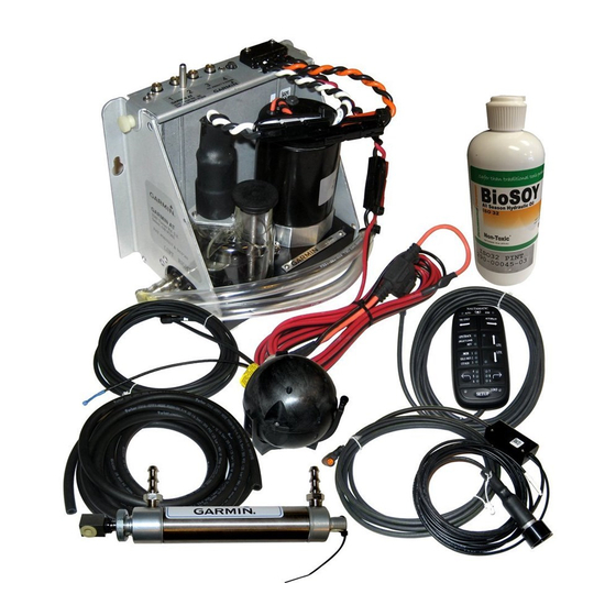
Figure 1 Finished steering actuator
CAUTION: This kit fits the long and extra long shaft motors only. It will not fit the short shaft version.
PN 906-1075-00
Page 1

Related Manuals for Garmin tr-1 gold


Summary of Contents for Garmin tr-1 gold
- Page 1 TR-1 Gold Cylinder & Bracket Mounting Instructions Honda 8 HP: 2001 & Newer Honda 9.9 HP: 2001 & Newer Honda 15 HP: 2003 & Newer Honda 20 HP: 2003 & Newer Figure 1 Finished steering actuator CAUTION: This kit fits the long and extra long shaft motors only. It will not fit the short shaft version.
- Page 2 Cylinder Mounting Parts Bracket Kit Honda 8-20 HP PN 120-1070-00 ITEM PART No. NAME 330-1071-01 Standoff, Upper (Short) 330-1071-02 Standoff, Lower (Long) 130-1072-00 Bracket, Rod Eye Mounting 330-1013-00 Pin, Stern Pivot 380-1074-00 Channel, Cylinder MTG. 380-1075-00 Plate, Channel Doubler 310-0260-90 Hex Cap M8 X 90 MM 130-0084-00 “U”...
- Page 3 Cylinder Kit PN 120-0900-00 ITEM PART NO. NAME 330-1002-00 Rod Eye, 5/16-24 310-0042-09 Hex Jam Nut 5/16-24 340-0900-00 Cylinder 321-0001-00 Fitting, Straight 1/8 NPT X 1/4 330-1101-00 Zinc Anode (Replaceable) 310-0040-26 Washer, Flat, Nylon 1/4 ID X .03 328-0901-00 Bushing 1/4 ID X 5/16 OD X 1/4”L 328-0902-00 Cylinder Tail Bushing I.
- Page 4 Step One: Turn the steering friction lock in the motor (just above the clamps and below the shift lever) all the way to the left. (Full free steering rotation. See motor manual if necessary.) The motor must steer very freely for the autopilot to work. If there is still any drag in the steering loosen the nut that is controlled by the friction lever to eliminate it.
- Page 5 Put a little thread locker on the second 8MM (item 8) bolt and install it through the other Lock Washer (item 9), the sandwich of the Cylinder Mounting Channel (item 6) and Doubler Plates (item 7) created at Fig. 6, the upper Short Standoff (item 2), and into the upper motor vibration isolation mount.
- Page 6 Figure 11-a Figure 11 Step Four: Put cylinder Rod Eye block (item 31) down over the pin in the Rod Eye Mounting Bracket (item 4). See Figure 11-a. Turn the Cylinder (item 34) so that the Fittings (item 35) point up (toward the top of the motor).
- Page 7 Step Six: Adjust the cylinder travel both directions. Turn the motor hard over to port. That will retract the Cylinder rod into the Cylinder. See Figure 13. Check that the Cylinder rod is still free to retract at least a little more. Next turn the motor hard over to starboard.