HP 5400R zl2 Series Nstallation And Getting Started Manual
Hide thumbs
Also See for 5400R zl2 Series:
Table of Contents
Table of Contents
Troubleshooting

Related Manuals for HP 5400R zl2 Series


Summary of Contents for HP 5400R zl2 Series
- Page 1 HP 5400R zl2 Switches Installation and Getting Started Guide Power over Ethernet...
- Page 3 HP 5400R zl2 Switches Installation and Getting Started Guide...
- Page 4 HP 5412R 92GT PoE+ / 4SFP+ (No PSU) v3 zl2 Switch JL001A BUT NOT LIMITED TO, THE IMPLIED WARRANTIES OF HP 5406R 8-port 1/2.5/5/10GBASE-T PoE+ / 8-port SFP+ (No PSU) v3 zl2 JL002A MERCHANTABILITY AND FITNESS FOR A PARTICULAR Switch PURPOSE.
-
Page 5: Table Of Contents
1 Introducing the HP 5400R zl2 Switches Overview of HP 5400R zl2 Switches ....... . 1-2 HP 5406R zl2 Switches . - Page 6 Installation Precautions ........2-6 Installation Precautions (continued) .
- Page 7 Downloading New Software ........5-15 HP Customer Support Services ........5-15 Before Calling Support .
- Page 8 B Cabling and Technology Information Cabling and Technology Information Specifications ... . B-1 Technology Distance Specifications ......B-3 Mode Conditioning Patch Cord .
- Page 9 Regulatory Model Identification Number ..... C-10 D Recycle Statements Waste Electrical and Electronic Equipment (WEEE) Statements ..D-1 Index...
-
Page 11: Introducing The Hp 5400R Zl2 Switches
Introducing the HP 5400R zl2 Switches The HP 5400R zl2 switches include the 5406R zl2 switch, 5412R zl2 switch and their bundles. They are multi-port modular switches that provide Layer 3 routing features, and also low latency for high-speed networking. -
Page 12: Overview Of Hp 5400R Zl2 Switches
Overview of HP 5400R zl2 Switches Overview of HP 5400R zl2 Switches HP 5406R zl2 Switches ■ The HP 5406R zl2 switch is available as an open 6-slot chassis (J9821A) with Premium Software. The HP 5406R-8XGT/8SFP+ (No PSU) v2 zl2 Switch (J9868A) ships with ■... - Page 13 Introducing the HP 5400R zl2 Switches Overview of HP 5400R zl2 Switches ■ The HP 5406R 8p1PoE0GT 8pSFP+ v3 zl2 Switch (JL003A) ships with the following: • One HP 5406R zl2 Switch (J9821A) • One HP 24p 10/100/1000BASE-T PoE+ v3 zl2 Mod (J9986A) •...
-
Page 14: Hp 5412R Zl2 Switches
Introducing the HP 5400R zl2 Switches Overview of HP 5400R zl2 Switches HP 5412R zl2 Switches ■ The HP 5412R zl2 switch is available as an open 12-slot chassis (J9822A) with Premium Software. ■ The HP 5412R-92G-PoE+/2SFP+ (No PSU) v2 zl2 Switch (J9825A) ships with the 5412R 12 slot chassis with Premium Software and the following: •... -
Page 15: Hp 5406R Zl2 Switch
Overview of HP 5400R zl2 Switches HP 5406R zl2 Switch The HP 5406R zl2 switch ships with the 5400R zl2 Management Module and open, 6-slot chassis (J9821A). The switch needs at least one power supply to operate. The 5406R zl2 switch bundles are not shown. -
Page 16: Hp 5412R Zl2 Switch
Overview of HP 5400R zl2 Switches HP 5412R zl2 Switch The HP 5412R zl2 switch ships with the 5400R zl2 Management Module and open, 12-slot chassis (J9822A). It does not ship with any power supplies. The switch needs at least one power supply to operate. The 5412R zl2 switch bundles are not shown. -
Page 17: Network Connectivity, Speeds And Technologies
Introducing the HP 5400R zl2 Switches Network Connectivity, Speeds and Technologies Network Connectivity, Speeds and Technologies These products support optional network connectivity as follows: Table 1-1. Optional Network Connectivity, Speeds and Technologies Transceiver Form-Factor and Connector Speed Technology Cabling SFP+... -
Page 18: Front Of The Switch
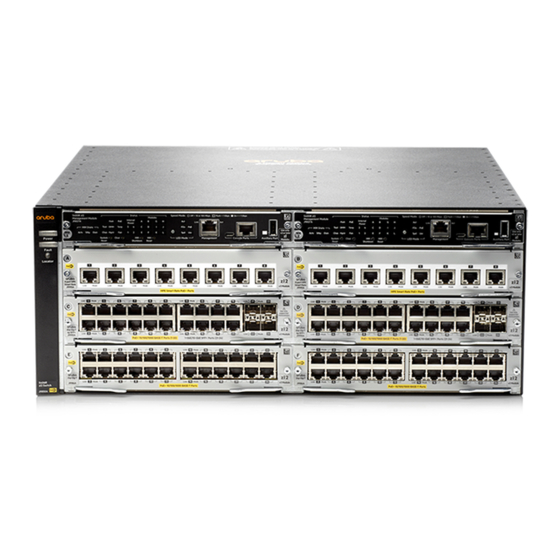
Introducing the HP 5400R zl2 Switches Front of the Switch Table 1-1. Optional Network Connectivity, Speeds and Technologies For supported transceivers, visit www.hp.com/networking/support – In the first textbox, type J4858 (for 100-Mb and Gigabit information), or J8436 (for 10-Gigabit information). - Page 19 This illustration shows the 5406R zl2 Switch, but the labeling and descriptions apply to all of the HP 5400R zl2 switches. For more information on HP Smart Rate port LEDs and 40G ports, see HP Switch v3 zl2 module installation guide.
-
Page 20: Leds
Introducing the HP 5400R zl2 Switches Front of the Switch LEDs As described in the next two tables, there are LEDs on the switch chassis and on the switch modules that keep you informed of the status of the switch and the network connections. - Page 21 Introducing the HP 5400R zl2 Switches Front of the Switch LEDs State Meaning Blinking If Flash, Fault, and Self Test LEDs are blinking, Secure digital card failed self-test. Orange If Flash and Fault LEDs are blinking, an operational fault has occurred.
- Page 22 Introducing the HP 5400R zl2 Switches Front of the Switch LEDs State Meaning Modules (green - A module is installed in the switch module slot corresponding to the letter and the module letters is undergoing or has passed self test. This also occurs when you install a module when corresponding to the switch is already powered on (“hot swap”).
- Page 23 See “LED Mode Select Button and Indicator LEDs” below for more information. The blinking behavior is an on/off cycle once every 1.6 seconds, approximately. For more information on HP Smart Rate port LEDs and 40G ports, see HP Switch v3 zl2 module installation guide. 1-13...
-
Page 24: Led Mode Select Button And Indicator Leds
Introducing the HP 5400R zl2 Switches Front of the Switch LED Mode Select Button and Indicator LEDs To optimize the amount of information that can be displayed for each of the switch ports, the 5400R zl2 switches use a Mode LED for each port. The... -
Page 25: Console Port
• Off = Not linked • Fast Flash = 40 Gbps For more information on HP Smart Rate port LEDs and 40G ports in speed mode, see HP Switch v3 zl2 module installation guide. ■ If the PoE indicator LED is lit, the Link and Mode LEDs indicate PoE... -
Page 26: Out-Of-Band Management (Oobm) Port
To use: connect an RJ-45 network cable to the Management port to manage an HP 5400R zl2 Switch through Telnet from a remote PC or a UNIX worksta- tion. To use this port, the switch must have an IP address. IP settings can be configured through a Console port connection or automatically from a DHCP/ Bootp server. -
Page 27: Mm Shutdown Button
Introducing the HP 5400R zl2 Switches Front of the Switch This button is provided for your convenience, but its presence means that if you are concerned with the security of the switch configuration and operation, you should make sure the switch is installed in a secure location, such as a locked wiring closet. - Page 28 Introducing the HP 5400R zl2 Switches Front of the Switch If the system is running with two management modules and the MM shutdown button is pressed on the standby module, no failover occurs. 1-18...
-
Page 29: Back Of The Switch
Introducing the HP 5400R zl2 Switches Back of the Switch Back of the Switch Figure 1-5. Back of a 5406R zl2 switch with one power supply Ground lug mounting holes AC power connector Power and Fault LEDs Slot for installing optional redundant power supply Figure 1-6. -
Page 30: Power Connector
N o t e Any combination of J9828A, J9829A and J9830A power supplies can be used in the same switch. However, HP recommends to only use like supplies in a unit for more deterministic behavior in event of a power supply failure. - Page 31 To reset the interface modules, pull each module out about half way and then re-seat them. Do this for each module in slots G-L. For more information regarding power see the: ■ HP Switch v2 zl Internal Power Supplies Installation Guide. ■ HP Power over Ethernet (PoE/PoE+) Devices Planning and Implemen- tation Guide.
-
Page 32: Switch Accessories
HP 5412R zl2 Switch ■ HP X450 4U/7U Universal 4-Post Rack Mounting Kit ■ ■ HP 5412R 92GT PoE+ / 4SFP+ (No PSU) v3 zl2 Switch (JL001A) HP 5406R 8-port 1/2.5/5/10GBASE-T PoE+ / 8-port SFP+ (No PSU) v3 zl2 ■ Switch (JL002A) ■... - Page 33 HP 8p 1/HP 2.5/5/XGT PoE+ v3 zl2 Mod (J9995A) ■ o t e For detailed information about the v2 zl modules, see the HP Switch v2 zl Modules Installation Guide. For detailed information about the v3 zl2 modules, see the HP Switch v3 zl2 Modules Installation Guide.
-
Page 34: Switch Features
(CLI) and a slightly reduced feature set accessible through an intuitive menu interface • Intelligent Management Center - a SOA based HP Network manage- ment application that accurately discovers and displays your switch on network maps and provides a graphical interface for configuring and monitoring your switch ■... - Page 35 Support for many other advanced features to enhance network perfor- mance, security, and control - for a description, see the Management and Configuration Guide which is on the HP networking Web site. Support for IEEE 802.3af standard, IEEE 802.3at standard, and ■...
- Page 36 Introducing the HP 5400R zl2 Switches Switch Features 1-26...
-
Page 37: Installing The Hp 5400R Zl2 Switches
■ One HP 5400R zl2 Management Module (J9827A) ■ ■ One HP 5406R zl2 Switch Fan Tray (J9831A) or HP 5412R zl2 Switch Fan Tray (J9832A) ■ One HP 5406R zl2 Switch Rack Mounting Kit (5066-3042) or HP 5412R zl2... -
Page 38: Switch Accessories
Switch One HP 5400R zl2 Management Module One HP 5400R zl2 Management Module (J9827A) (J9827A) One HP 5406R zl2 Switch Fan Tray One HP 5412R zl2 Switch Fan Tray (J9831A) (J9832A) Power Cords Power cord, use one of the following according to the country of usage:... - Page 39 Installing the HP 5400R zl2 Switches Included Parts Country/Region J9829A Power Supply Cable Australia 8121-1476 China 8121-1484 Europe/South Korea 8121-1479 Japan 8120-5338 Thailand/Philippines 8121-1485 Denmark 8121-1486 Switzerland 8121-1480 United Kingdom/Hong Kong/Singapore/ Malaysia 8121-1475 South Africa/India 8121-1483 Taiwan 8121-1511 Israel 8121-1478...
-
Page 40: Installation Procedures
N o t e Make sure you use only HP Switch v2 zl or v3 zl2 Modules in your 5400R zl2 switches. HP switch vl zl modules are not supported. 2-12). The 5406R zl2 and 5412R zl2... - Page 41 Installing the HP 5400R zl2 Switches Installation Procedures Connect the switch to a power source (page 2-21). Once the switch is mounted, plug it in to the nearby main power source. Connect the network devices (page 2-22). Using the appropriate network cables, connect other switches, hubs, routers, computers, servers, printers, and other network devices to the switch ports.
-
Page 42: Installation Precautions
Installing the HP 5400R zl2 Switches Installation Procedures Installation Precautions Follow these precautions when installing your 5400R zl2 switch: W A R N I N G ■ Devices installed in a rack or cabinet should be mounted as low as possible, with the heaviest device at the bottom and progres- sively lighter devices installed above. -
Page 43: Installation Precautions (Continued)
Installation Procedures Installation Precautions (continued) C a u t i o n s If the switch is to be shipped in a rack, HP Shock Rack and an HP X4504U/ ■ 7U Universal 4-Post Rack Mount Kit (J9852A) for each switch. -
Page 44: Prepare The Installation Site
C a u t i o n Make sure you install only HP Switch v2 zl or v3 zl2 Modules. HP Swtich vl zl modules are not supported. Avoid any electrostatic discharge problems by handling the modules only by their bulkheads. - Page 45 Installing the HP 5400R zl2 Switches Installation Procedures ■ The modules can be “hot swapped”, installed after the switch is already powered on, and normally will be immediately operational. See “Hot Swapping the Switch Module” on page 2-27. Ensure you fully insert the modules. That is, press the module into ■...
-
Page 46: Installing A Management Module Battery
Installing the HP 5400R zl2 Switches Installation Procedures Installing a Management Module Battery The battery on the management module is used to keep time for the internal switch clock. The internal clock will not function properly without a battery. W A R N I N G ■... - Page 47 Installing the HP 5400R zl2 Switches Installation Procedures Mettre au rebut les batteries usagées conformément aux instructions du fabricant. Perchlorate Notice. If this product contains a real-time clock battery or coin cell battery it may contain perchlorate and may require special handling when recycled or disposed of in California and other certain states.
-
Page 48: Optional) Install Another Power Supply
N o t e Any combination of J9828A, J9829A and J9830A power supplies can be used in the same switch. However, HP recommends to only use like supplies in a unit for more deterministic behavior in event of a power supply failure. - Page 49 Installing the HP 5400R zl2 Switches Installation Procedures C a u t i o n The switch power supplies are hot swappable; they can be installed while the switch is receiving power from the supply in the other slot. But, as indicated by the caution statement on the power supply, the supply must not be connected to AC power before being installed or removed.
-
Page 50: Verify The Switch Passes Self Test
Installing the HP 5400R zl2 Switches Installation Procedures Figure 2-2. Installing a power supply Handle to insert the power supply into the Chassis. Screws Once the power supply is installed, tighten the four retaining screws that hold it in place. The screws can be tightened with either a flat-bladed or Torx T-10 screwdriver. - Page 51 Installing the HP 5400R zl2 Switches Installation Procedures Figure 2-3. Power connector on back of switch N o t e The 5400R zl2 switches do not have a power switch. They are powered on when the power cord is connected to the switch and to a power source.
-
Page 52: Led Behavior
Installing the HP 5400R zl2 Switches Installation Procedures LED Behavior: During the self test: Initially, Power, Fault, Locator, and all the switch chassis LEDs are on. Then, ■ after approximately 30 seconds, all the module LEDs go on as the modules... -
Page 53: Rack Or Cabinet Mounting
Installing the HP 5400R zl2 Switches Installation Procedures Rack or Cabinet Mounting The 5400R zl2 switches are designed to be mounted in any EIA-standard 19- inch telco rack or in an equipment cabinet such as a server cabinet. If you are installing the switch in an equipment cabinet, read the following “Equipment... - Page 54 Installing the HP 5400R zl2 Switches Installation Procedures Install a screw half-way into this cage nut. Align the included Rack Mount Bracket such that the half-hole lines up with the screw, install additional cage nuts at each hole position in the bracket.
- Page 55 Installing the HP 5400R zl2 Switches Installation Procedures Repeat for opposite column in the rack. Secure the Rack Mount Brackets to the switch with included flat head screws. Pan Head Screw Cable Manager Pan Head Screw 2-19...
-
Page 56: Horizontal Surface Mounting
Installing the HP 5400R zl2 Switches Installation Procedures Install the retainer horizontally Rotate the retainer to the vertical position N o t e Use only the included 6 mm/0.24 inch flat head screws. Using any of the 8 mm/ 0.31 inch screw included in other rack mounting kits interferes with internal components. -
Page 57: Connect The Switch To A Power Source
Installing the HP 5400R zl2 Switches Installation Procedures Crimp the grounding lug to a properly grounded grounding wire. Re-attach the grounding lug to the switch with the two screws. Figure 2-5. Attaching grounding lug to the 5400R zl2 switch Grounding Lug Grounding Lug Screws 7. -
Page 58: Connect The Network Cables
Installing the HP 5400R zl2 Switches Installation Procedures 8. Connect the Network Cables The type of network connections you will need to use depends on the types of switch modules you have installed in your 5400R zl2 Switch. See the documentation accompanying the modules for cabling configurations and procedures for those modules. -
Page 59: Optional) Connect To The Management Console Of The Switch
Installing the HP 5400R zl2 Switches Installation Procedures 10. (Optional) Connect to the Management Console of the Switch The 5400R zl2 switches have a full-featured, easy to use console interface for performing the following tasks: ■ Monitor switch and port status and observe network activity counters ■... -
Page 60: Setting Up A Console Connection
A DB9-to-RJ45 cable (shipped with the switch). b. A micro-USB cable (not provided). The USB console drivers are available at www.hp.com/networking/support. The following are the steps to download the driver: Type a product model (for example, 5400) or product number in the Auto Search text box. - Page 61 Installing the HP 5400R zl2 Switches Installation Procedures Figure 2-6. Console Connection Console Port RJ-45 to DB9 console cable supplied with the switch Optional USB console cable (not supplied) To PC running a terminal emulator program, or a VT-100 terminal Power on the management console (terminal or PC).
-
Page 62: Console Cable Pinouts
Installing the HP 5400R zl2 Switches Installation Procedures Console Cable Pinouts The console cable has an RJ-45 plug on one end and a DB-9 female connector on the other end. Table 2-2 describes the mapping of the RJ-45 to DB-9 pins module. -
Page 63: Out-Of-Band Management (Oobm) Port
To use: connect an RJ-45 network cable to the Management port to manage an HP 5400R zl2 Switch through Telnet from a remote PC or a UNIX worksta- tion. To use this port, the switch must have an IP address. IP settings can be configured through a Console port connection or automatically from a DHCP/ Bootp server. -
Page 64: Adding Or Replacing Modules
Installing the HP 5400R zl2 Switches Hot Swapping Switch Modules Adding or Replacing Modules If a module has to be replaced with one of the same type, or you are expanding the switch capability by adding a module in a slot where one was not previ- ously installed (since the last switch reboot), the replaced or new module is immediately operational;... -
Page 65: Getting Started With Switch Configuration
SNMP manage- ment tool, Intelligent Management Center, see the Management and Config- uration Guide on the HP networking Website. Recommended Minimal Configuration In the factory default configuration, the switch has no IP (Internet Protocol) address and subnet mask, and no passwords. -
Page 66: Using The Switch Setup Screen
By default, the switch is configured to acquire an IP address configuration from a DHCP or Bootp server. To use DHCP/Bootp instead of the manual method described in this chapter, see “DHCP/Bootp Operation” in the Management and Configuration Guide which is on the HP networking Website. Using the Switch Setup Screen... - Page 67 Press Enter, then S (for Save). The following is information on the fields in the Setup screen. For more information on these fields, see the Management and Configuration Guide which is on the HP networking Web site. Parameter Default System Name blank Optional;...
-
Page 68: Where To Go From Here
5400R zl2 switches, see the Management and Configuration Guide which is on the HP networking Web site. To Recover from a Lost Manager Password: If you cannot start a con-... -
Page 69: Using The Ip Address For Remote Switch Management
Press a key, and you will then see the switch console command (CLI) prompt, for example (assuming there is no password): HP 5400Rzl2# Enter help or ? to see a list of commands that can be executed at the prompt. - Page 70 Figure 3-2. Switch Web Browser Interface - Status Overview For more information on using the web browser interface, please see the Management and Configuration Guide which is on the HP networking Web site. An extensive help system is also available for the web browser interface. To...
-
Page 71: Replacing Components
2-1) H o t S w a p p i n g The HP 5400R zl2 Switch supports “hot swapping” - the ability to replace the following hardware components while the switch is operating: a fan tray, power supply (if a second power supply is installed), and interface module. -
Page 72: Replacing Power Supplies
Replacing Power Supplies Replacing Power Supplies If your HP 5400R zl2 Switch is configured with redundant power supplies, you will not suffer any loss of traffic or performance if a power supply fails. Replace the failed component as soon as possible. One of the Internal Power LEDs on the management module will blink simultaneously with the switch Fault LED indicating which power supply failed. - Page 73 Figure 4-2. Power supply installation Tighten the four retaining screws that hold it in place. Be careful not to overtighten the screws. For more details, see the HP Switch zl2 Internal Power Supply Installation Guide.
-
Page 74: Replacing Fan Trays
Replacing Components Replacing Fan Trays Replacing Fan Trays When a fan fails the Fan Status LED on the management module blinks simultaneously with the switch Fault LED. In this case, the entire fan tray needs to be replaced. You cannot replace individual fans. The fan tray is hot swappable. -
Page 75: Replacing The Management Module
The switch does not have to be powered off to remove the management module, however, when the management module is removed all ports will lose communication. HP networking recommends replacing all components during the scheduled down time. To install (or replace) a Management Module: On the module, unscrew the retaining screws enough to disconnect them from the threaded holes in the switch. -
Page 76: Replacing The Management Module Sd Card
Replacing Components Replacing the Management Module SD Card Extractor handles Retaining screws You can use MM Shutdown button to replace an active Management Module. This helps the standby MM to become active. Replacing the Management Module SD Card The SD card is the primary non-volatile storage medium located on the management module that contains both the boot software and configuration files. - Page 77 Replacing Components Replacing the Management Module SD Card Figure 4-6. Secure Digital installation and removal Slide out the old SD card. Slide in the new SD card being careful not to bend any pins. Reinstall the management module into the switch. Use an equal amount of pressure and push both extractor handles closed to completely seat the module.
- Page 78 Replacing Components Replacing the Management Module SD Card...
-
Page 79: Troubleshooting
IMC, the SNMP-based network manage- ment tool. For more information, see the chapter “Troubleshooting” in the Management and Configuration Guide, which is on the HP networking Web site at www.hp.com/networking/support. This chapter describes the following:... -
Page 80: Basic Troubleshooting Tips
The 5400R zl2 switches also support Trunking, which allows multiple network cables to be used for a single network connection without causing a data path loop. See the Management and Configuration Guide for more information on Spanning Tree and on Trunking, which is on the HP networking Web site. - Page 81 For more information on possible network problems and their solutions, refer to the technical note “Troubleshooting LAN Performance and Intermittent Connectivity Problems”, which can be found on the HP networking Web site in the Reference Library, www.hp.com/networking/support, in the A-Z index...
-
Page 82: Diagnosing With The Leds
Troubleshooting Diagnosing with the LEDs Diagnosing with the LEDs Table 5-1 shows LED patterns on the switch and the switch modules that indicate problem conditions. Check in the table for the LED pattern you see on your switch Refer to the corresponding diagnostic tip on the next few pages. Table 5-1. -
Page 83: Diagnostic Tips
➍ The module Ensure you have installed a zl or zl2 module in the slot. The HP xl/gl/vl modules will installed in the slot not fit in the interface module slots in 5400R zl2 family, and they are not compatible that corresponds to with HP 5400R zl2 switch. - Page 84 As HP networking introduces new modules for your HP 5400R zl2, you may have to update the switch with new operating code that supports the new module. The documentation that came with the module will indicate which version of the operating code is needed to support the module.
- Page 85 Call your authorized corresponding to reseller or authorized service provider, or use the electronic support services from the blinking HP networking to get assistance. See the Customer Support/Warranty card for more number. information. ➑...
- Page 86 For more information on the Port Security feature, see the Management and has been detected Configuration Guide which is on the HP networking Web site. See page 5-1 on the port. details. For more information on 40G port self-test or initialization failure, see v3 zl2 module...
- Page 87 • Verify you have used the correct cable type for the connection. – for any of the twisted-pair connections, in the default configuration (Auto), either a straight-through or a crossover cable can be used and the switch will automatically adjust its operation. See the “HP Auto-MDIX Feature” description on page B-8 for more information.
-
Page 88: Hp Networking Tools
The console interface is also accessible through a telnet connection. See the “Troubleshooting” chapter in the Management and Configuration Guide for more information on using these software tools to diagnose and manage your switch, which is on the HP networking Website. See page 5-1 details. 5-10... -
Page 89: Hardware Diagnostic Tests
Troubleshooting Hardware Diagnostic Tests Hardware Diagnostic Tests Reasons for Resetting the Switch Generally, you only need to reset the switch when it needs to recognize a change in its hardware or software (console) configuration. Some circumstances in which you will need to reset the switch are: ■... -
Page 90: Checking The Switch Leds
Troubleshooting Hardware Diagnostic Tests Power cycling the switch, pressing the System Reset button, and the software reset or reboot options all cause the switch to perform its power-on self-test, which almost always will resolve any temporary operational problems. These reset processes also cause any network traffic counters to be reset to zero and cause the System Up Time timer to reset to zero. -
Page 91: Testing Twisted-Pair Cabling
HP networking also offers a wire testing service. Contact your HP authorized reseller or authorized service provider or your local HP networking sales office for more information. -
Page 92: Restoring The Factory Default Configuration
For both the save and restore processes, you can use the console copy command. See the switch Management and Configura- tion Guide which is on the HP networking Web site. See page 5-1 for details. -
Page 93: Downloading New Software
Additionally, your HP authorized network reseller can provide you with assistance, both with services that they offer and with services offered by HP networking. Before Calling Support Before calling your networking dealer or HP Support, to make the support... - Page 94 Troubleshooting HP Customer Support Services 5-16...
-
Page 95: Physical
30.74 cm (12.1 in) Weight: • 5406R zl2 Switch base system(J9821A) 11.11 kg (24.5 lbs) • 5412R zl2 Switch base system(J9822A) 17.28 kg (38.1 lbs) Electrical The HP zl2 Power Supply Specifications: Electrical J9828A J9829A J9830A Main AC voltage: 100 -127 volts; 200 - 240 volts 110 -127 volts;... -
Page 96: Environmental
Specifications Environmental Operating Non-Operating Temperature: 0°C to 45°C (32°F to 113°F) -40°C to 70°C (-40°F to 158°F) Relative humidity: 15% to 95% at 45°C (113°F) 15% to 95% at 65°C (149°F) (non-condensing) Maximum altitude: up to 3.1 km (10,000 ft) 4.6 km (15,000 ft) If you are installing J8177Ctransceiver, the operating ambient temperature must not exceed 40°C (104°F) and must not exceed 35°C (99°F), if FIPS Opacity Shield is installed. -
Page 97: Safety
IEEE 802.3i 10BASE-T 100-TX IEEE 802.3u 100BASE-TX 1000-T IEEE 802.3ab 1000BASE-T 10GBASE-T IEEE 802.3an 10GBASE-T 2.5G and 5G HP Smart Rate Twisted- Pair Copper 100-FX IEEE 802.3u Class 1 Laser 100BASE-FX IEC60825-1 Product for all Laser Klasse 1 100-BX IEEE 802.3ah... - Page 98 Specifications Table A-1. Technology Standards and Safety Compliance (Continued) Laser safety information Technology Compatible EN/IEC SFP+ Media Standards standard Lasers Lasers Lasers Converter compliance Lasers 1000-LH EN/IEC 60825 Class 1 Laser Product Laser Klasse 1 1000-BX IEEE 802.3ah EN/IEC 60825 Class 1 Laser 1000BASE-BX10 Product...
- Page 99 Specifications Table A-1. Technology Standards and Safety Compliance (Continued) Laser safety information Technology Compatible EN/IEC SFP+ Media Standards standard Lasers Lasers Lasers Converter compliance Lasers 40-Gig eSR4 IEEE 802.3ba EN/IEC 60825 Class 1 Laser Product 40GBASE-SR4 Laser Klasse 40-Gig LR4 IEEE 802.3ba EN/IEC 60825 Class 1 Laser...
- Page 100 Specifications...
-
Page 101: B Cabling And Technology Information
Rate Cable Requirements below. 5 Gbps Operation Category 5e or better, 100-ohm 4-pair UTP or STP cable. Category 6 or better is recommended. See note on HP Smart Rate Cable Requirements below. 10 Gbps Operation Category 6 or 6A, 100-ohm 4-pair UTP cable, or Category 6A or 7, 100-ohm 4-pair STP cable, complying with IEEE 802.3an 10GBASE-... - Page 102 Category 5e or Class D limits described in the ANSI/TIA/EIA 568-C.2 and ISO/ IEC 11801 standards, respectively. Note on HP Smart Rate 5 Gb/s Cable Requirements. The 5 Gb/s Smart Rate operates on the majority of Category 5e and Category 6 cable installations.
-
Page 103: Technology Distance Specifications
For 10GBASE-T, Category 6 patch cables are sensitive to movement once link has been established, and could cause link to drop if moved. Therefore, HP recommends using Category 6A patch cables, or using cable management options to tie down (dress) the Category 6 patch cables so they cannot move. - Page 104 Cabling and Technology Information Table B-2. Technology Supported cable type Multimode fiber Supported distances modal bandwidth 10GBASE-T Cat 6 unshielded - up to 55 meters twisted-pair copper Cat 6 shielded - up to 100 meters Cat 6A unshielded - up to 100 meters Cat 6A shielded - up to 100 meters Cat 7 shielded - up to 100 meters...
- Page 105 Cabling and Technology Information Table B-2. Technology Supported cable type Multimode fiber Supported distances modal bandwidth 40-Gig ESR4 multimode fiber 2000 MHz*km 2- 300 meters 4700 MHz*km 2- 400 meters 40-Gig LR4 single mode fiber 2- 10,000 meters Cat 5e cabling requires testing to 200 MHz operation and additionally for ANEXT and AELFEXT. The maximum supported distances may be reduced depending on alien crosstalk levels.
-
Page 106: Mode Conditioning Patch Cord
Cabling and Technology Information Mode Conditioning Patch Cord Mode Conditioning Patch Cord The following information applies to installations in which multimode fiber- optic cables are connected to a Gigabit-LX port or a 10-Gigabit LRM port. Multimode cable has a design characteristic called “Differential Mode Delay”, which requires the transmission signals be “conditioned”... - Page 107 Cabling and Technology Information Mode Conditioning Patch Cord If you connect the patch cord directly to the network cabling, you may need to install a female-to-female adapter to allow the cables to be connected together. Gigabit-LX port To network multimode Mode Conditioning cabling Patch Cord...
-
Page 108: Twisted-Pair Cable/Connector Pin-Outs
N o t e HP Auto-MDIX was developed and shared with the IEEE for the development of the IEEE 802.3ab standard. HP Auto-MDIX and the IEEE 802.3ab Auto MDI/ MDI-X feature are completely compatible. If you connect a 5400R zl2 Switch twisted-pair port to another switch or hub, which typically have MDI-X ports, the 5400R zl2 Switch port automatically operates as an MDI port. - Page 109 Cabling and Technology Information Twisted-Pair Cable/Connector Pin-Outs ■ For 10 Mbps connections to the ports, you can use Category 3, 4, or 5 100-ohm differential unshielded twisted-pair (UTP) or shielded twisted- pair (STP) cable, as supported by the IEEE 802.3 10Base-T standard. For 100 Mbps connections to the ports, use Category 5 100-ohm differen- ■...
-
Page 110: Straight-Through Twisted-Pair Cable For 10 Mbps Or 100 Mbps Network Connections
Straight-Through Twisted-Pair Cable for 10 Mbps or 100 Mbps Network Connections Because of the HP Auto-MDIX operation of the 10/100 ports on the switches, for all network connections, to PCs, servers or other end nodes, or to hubs or other switches, you can use straight-through cables. - Page 111 Cabling and Technology Information Twisted-Pair Cable/Connector Pin-Outs receive + transmit + receive - transmit - transmit + receive + transmit - receive - B-11...
-
Page 112: Crossover Twisted-Pair Cable For 10 Mbps Or 100 Mbps Network Connection
Crossover Twisted-Pair Cable for 10 Mbps or 100 Mbps Network Connection The HP Auto-MDIX operation of the 10/100 ports on the switches also allows you to use crossover cables for all network connections, to PCs, servers or other end nodes, or to hubs or other switches. - Page 113 Cabling and Technology Information Twisted-Pair Cable/Connector Pin-Outs receive + transmit - receive - transmit + transmit + receive - transmit - receive + B-13...
-
Page 114: Straight-Through Twisted-Pair Cable For 1000 Mbps Network Connections
Cabling and Technology Information Twisted-Pair Cable/Connector Pin-Outs Straight-Through Twisted-Pair Cable for 1000 Mbps Network Connections 1000Base-T connections require that all four pairs or wires be connected. Cable Diagram Figure B-4. Straight-through Cable Diagram for 1000 Mbps Network Connection N o t e Pins 1 and 2 on connector “A”... -
Page 115: Pin Assignments
Cabling and Technology Information Twisted-Pair Cable/Connector Pin-Outs Pin Assignments For 1000Base-T operation, all four pairs of wires are used for both transmit and receive. B-15... - Page 116 Cabling and Technology Information Twisted-Pair Cable/Connector Pin-Outs B-16...
-
Page 117: C Safety And Regulatory Statements
Safety and Regulatory Statements Safety Information Documentation reference symbol. If the product is marked with this symbol, refer to the product documentation to get more information about the product. WARNING A WARNING in the manual denotes a hazard that can cause injury or death. -
Page 118: Informations Concernant La Sécurité
Safety and Regulatory Statements Informations concernant la sécurité Informations concernant la sécurité Symbole de référence à la documentation. Si le produit est marqué de ce symbole, reportez-vous à la documentation du produit afin d'obtenir des informations plus détaillées. WARNING Dans la documentation, un WARNING indique un danger susceptible d'entraîner des dommages corporels ou la mort. -
Page 119: Hinweise Zur Sicherheit
Safety and Regulatory Statements Hinweise zur Sicherheit Hinweise zur Sicherheit Symbol für Dokumentationsverweis. Wenn das Produkt mit diesem Symbol markiert ist, schlagen Sie bitte in der Produktdokumentation nach, um mehr Informationen über das Produkt zu erhalten. WARNING Symbol für Dokumentationsverweis. Wenn das Produkt mit diesem Symbol markiert ist, schlagen Sie bitte in der Produktdokumentation nach, um mehr Informationen über das Produkt zu erhalten. -
Page 120: Considerazioni Sulla Sicurezza
Safety and Regulatory Statements Considerazioni sulla sicurezza Considerazioni sulla sicurezza Simbolo di riferimento alla documentazione. Se il prodotto è contrassegnato da questo simbolo, fare riferimento alla documen- tazione sul prodotto per ulteriori informazioni su di esso. WARNING La dicitura WARNING denota un pericolo che può causare lesioni o morte. -
Page 121: Consideraciones Sobre Seguridad
Safety and Regulatory Statements Consideraciones sobre seguridad Consideraciones sobre seguridad Símbolo de referencia a la documentación. Si el producto va marcado con este símbolo, consultar la documentación del producto a fin de obtener mayor información sobre el producto. WARNING Una WARNING en la documentación señala un riesgo que podría resultar en lesiones o la muerte. -
Page 122: Informações De Segurança
Safety and Regulatory Statements Informações de Segurança Informações de Segurança Símbolo de referência à documentação. Se o produto estiver marcado com este símbolo, consulte a documentação do produto para obter mais informações sobre ele. AVISO Um AVISO no manual indica um perigo que possa causar ferimentos ou morte. -
Page 123: Safety Information (Japan
Safety and Regulatory Statements Safety Information (Japan) Safety Information (Japan) -
Page 124: Safety Information (China
Safety and Regulatory Statements Safety Information (China) Safety Information (China) -
Page 125: Emc Regulatory Statements
Safety and Regulatory Statements EMC Regulatory Statements EMC Regulatory Statements U.S.A. FCC Class A This equipment has been tested and found to comply with the limits for a Class A digital device, pursuant to Part 15 of the FCC Rules. These limits are designed to provide reasonable protection against interference when the equipment is operated in a commercial environment. -
Page 126: Japan
VCCI Class A Korea Taiwan Regulatory Model Identification Number For regulatory identification purposes, the HP 5400R zl2 Switches are assigned a Regulatory Model Number. The Regulatory Model Number for these switches is RSVLC- 1301. This regulatory number should not be confused with the marketing name (HP 5400R zl2 Switches), or product numbers (J8697A, J8698A, J8699A, and J8700A). -
Page 127: Waste Electrical And Electronic Equipment (Weee) Statements
Recycle Statements Waste Electrical and Electronic Equipment (WEEE) Statements Disposal of Waste Equipment by Users in Private Household in the European Union This symbol on the product or on its packaging indicates that this product must not be disposed of with your other household waste. - Page 128 Recycle Statements Waste Electrical and Electronic Equipment (WEEE) Statements Laitteiden hävittäminen kotitalouksissa Euroopan unionin alueella Jos tuotteessa tai sen pakkauksessa on tämä merkki, tuotetta ei saa hävittää kotitalousjätteiden mukana. Tällöin hävitettävä laite on toimitettava sähkölaitteiden ja elektronisten laitteiden kierrätyspisteeseen. Hävitettävien laitteiden erillinen käsittely ja kierrätys auttavat säästämään luonnonvaroja ja varmista- maan, että...
- Page 129 Recycle Statements Waste Electrical and Electronic Equipment (WEEE) Statements Smaltimento delle apparecchiature da parte di privati nel territorio dell'Unione Europea Questo simbolo presente sul prodotto o sulla sua confezione indica che il prodotto non può essere smaltito insieme ai rifiuti domestici. È responsabilità dell'utente smaltire le apparecchiature consegnan- dole presso un punto di raccolta designato al riciclo e allo smaltimento di apparecchiature elettriche ed elettroniche.
- Page 130 Para obter mais informações sobre locais que reciclam esse tipo de material, entre em contato com o escritório da HP em sua cidade, com o serviço de coleta de lixo ou com a loja em que o produto foi adquirido.
- Page 131 Recycle Statements Waste Electrical and Electronic Equipment (WEEE) Statements Изхвърляне на отпадъчно оборудване от потребители в частни домакинства в Европейския съюз Този символ върху продукта или опаковката му показва, че продуктът не трябва да се изхвърля заедно с другите битови отпадъци. Вместо това, трябва да предпазите човешкото здраве и околната среда, като...
- Page 132 Recycle Statements Waste Electrical and Electronic Equipment (WEEE) Statements...
- Page 133 … B-8 1000Base-T crossover cable pin-out … B-12 fiber-optic cable specifications … B-3 HP Auto-MDIX feature … B-8 MDI-X to MDI connections … B-10, B-14 MDI-X to MDI-X connections … B-12 pin-outs … B-10, B-15 Act LED … 1-12 straight-through cable pin-out …...
- Page 134 … 1-24 downloading new software … 5-15 hot swapping … 4-1 redundant power supply … 1-20, 2-13 switch modules … 2-27 HP Auto-MDIX electrical specifications … A-1 feature description … B-8 EMC regulatory statements … C-9 environmental specifications … A-2 equipment cabinet mounting the switch in …...
- Page 135 Fan Status … 1-10, 1-11 showing error conditions … 5-4 network cables Fault … 1-10 HP Auto-MDIX feature … B-8 behavior during self test … 2-16 required types … 2-8 showing error conditions … 5-4 twisted-pair connector pin-outs … B-8 FDx …...
- Page 136 … 5-14 console … 2-23 location of Reset button … 1-16 HP Auto-MDIX feature … B-8 troubleshooting procedure … 5-11 network connections … 2-22 routing features … 1-24 power connector … 1-20 Power LED behavior during error conditions …...
- Page 137 … B-10, B-14 field descriptions … 3-3 switch-to-switch or hub connection … B-12 testing … 5-13 twisted-pair ports HP Auto-MDIX feature … B-8 telnet access to the console … 2-26, 3-5 terminal configuration … 2-23 testing checking the console messages … 5-12 wiring rules for twisted-pair cables …...
- Page 138 6 – Index...
- Page 140 © Copyright 2005-2013, 2015 Hewlett-Packard Development Company, L.P. The information Manual Part Number contained herein is subject to change without notice. The only warranties for HP products and services are set forth in the express warranty statements accompanying such products and ser- 5998-7652 vices.