
Related Manuals for Panasonic AJ-SD93


Summary of Contents for Panasonic AJ-SD93
-
Page 1: Operating Instructions
Before operating this product, please read the instructions carefully and save this manual for future use. Printed in Japan VQT0L54-1 Operating Instructions Digital Video Cassette Recorder Model No. ENGLISH S0704A1074 -M... - Page 2 Canada. CAUTION: Operation at a voltage other than 120 V AC may require the use of a different AC plug. Please contact either a local or foreign Panasonic authorized service center for assistance in selecting an alternate AC plug. CAUTION: Even when the Power Switch is in the OFF position, a small current flows the filter circuit.
-
Page 3: Caution For Ac Mains Lead
If you lose the fuse cover the plug must not be used until a replacement cover is obtained. A replacement fuse cover can be purchased from your local Panasonic Dealer. IF THE FITTED MOULDED PLUG IS UNSUITABLE FOR THE SOCKET OUTLET IN YOUR HOME THEN THE FUSE SHOULD BE REMOVED AND THE PLUG CUT OFF AND DISPOSED OF SAFELY. -
Page 4: Operating Precaution
For AJ-SD93E IMPORTANT “Unauthorized recording of copyrighted television programmes, video tapes and other materials may infringe the right of copyright owners and be contrary to copyright laws.” THIS APPARATUS MUST BE EARTHED To ensure safe operation the three-pin plug must be inserted only into a standard three-pin power point which is effectively earthed through the normal house- hold wiring. -
Page 5: Table Of Contents
Contents Introduction ...6 Included accessories ...6 Optional boards ...6 Features ...7 Parts and their functions ...8 • Front Panel ...8 • Display Panel ...11 • Rear Panel ...12 Tapes ...13 IEEE 1394 digital interface...14 Joystick ...15 PF (Programmable Function) ...15 •... -
Page 6: Introduction
Introduction The model AJ-SD93 multi-purpose digital VTR uses small, 1/4-inch wide cassette tapes to record and play back images with a high picture quality at a video recording rate of 50 Mbps while it can also record and play back DVCPRO (25 Mbps) format tapes as well as play back consumer-use DV/DVCAM tapes. -
Page 7: Features
A cassette adapter (AJ-CS455P) is necessary when a mini DV cassette tape is to be used. Digital slow motion Panasonic's original digital slow-motion technology makes it possible to obtain clear pictures even during slow playback at speeds ranging from -0.43x to +0.43x. -
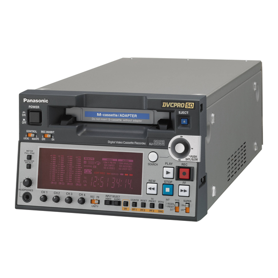
Page 8: Parts And Their Functions
Parts and their functions Front panel POWER switch Cassette insertion slot EJECT button When this button is pressed, the tape is unloaded and the cassette is ejected automatically a few seconds later. When CTL display has been selected for the counter display, the display is reset. - Page 9 Parts and their functions (continued) Front panel CONTROL LOCAL METER FULL/FINE MONITOR SEL HEADPHONES INPUT SELECT buttons These buttons are used to switch the video and audio input signals. They can also be used to switch the input signals to the internal reference signal selected as the setup menu item No.600 (INT SG) setting.
- Page 10 Parts and their functions (continued) Front panel CONTROL LOCAL METER FULL/FINE MONITOR SEL HEADPHONES Joystick This is used for shuttle, slow and other variable-speed playback. It is also used for the menu settings, etc. The stick can be moved upward, downward, to the left or to the right, and it can also be pressed to initiate operations.
-
Page 11: Display Panel
Parts and their functions (continued) Display panel Level meter This displays the levels of the PCM audio signals for CH1, CH2, CH3 and CH4. During recording and when the E-E mode is selected, it shows the levels of the input audio signals; during playback, it shows the levels of the output audio signals. -
Page 12: Rear Panel
Parts and their functions (continued) Rear panel VIDEO VIDEO DIGITAL AUTO VIDEO1 VIDEO2 VIDEO OUT REF VIDEO IN TIME CODE AUDIO IN DVCPRO AUDIO OUT IEEE 1394 digital input/output connector This enables signals to be input and output using the IEEE 1394 digital interface. -
Page 13: Tapes
• When consumer-use DV and DVCAM cassette tapes are used, the maximum time for STILL TIMER is set to 10 seconds. It is recommended that tapes bearing the Panasonic brand be used as the consumer-use DV tapes. EJECT POWER... -
Page 14: Ieee 1394 Digital Interface
IEEE 1394 digital interface The recording format for IEEE 1394 digital input data is determined based on the table below. Setup menu No. 012 Recording format Input data (SYS FORMAT) data settings DVCPRO50 DVCPRO50 DVCPRO Recording not possible Recording not possible DVCPRO50 Recording not possible DVCPRO... -
Page 15: Joystick
Joystick (1) Press the SEARCH button to activate the joystick. When STICK has been selected as the setup menu item No.100 (SEARCH ENA) setting, the joystick will be activated without pressing the SEARCH button. (2) Press the joystick to switch between the SHTL mode and SLOW mode. -
Page 16: Repeat Playback
Repeat playback Setting the BEGIN and END points (1) Press the MENU button. (2) Select menu item No.161 (CTL(TC)BGN) or No.162 (END), and incline the joystick to the left or right. By operating the joystick, the user can choose whether or not to set the BEGIN and END points. -
Page 17: Setup (Initial Settings)
Setup (initial settings) The unit’s main settings are performed while making selections using a menu-driven system. When a TV monitor is connected to the VIDEO MON connector on the unit’s rear panel, the setup menus will appear on the TV monitor. POWER CONTROL REC INHIBIT... -
Page 18: Setup Menus
Setup menus This VTR can hold five user files, each of which has its own specific menu settings, and one of these files can be selected for use. Changing the file (1) Press the MENU button. (2) When the FF button is pressed while holding down the PF button, the next user file is selected;... - Page 19 Setup menus (continued) Loading user files The contents of the USER2, USER3, USER4 or USER5 file can be copied (loaded) into the USER1 file. Also, the contents of the USER1 file can be copied (saved) into the USER2, USER3, USER4 or USER5 file.
-
Page 20: System Menu
Setup menus (continued) SYSTEM menu No./Item Description System phase adjustment: Variable range ±180 ° SYS SC –: Advanced, +: Delayed Note: 0000 –128 If setting operation is 0128 performed, the setting value does not return to factory (default) setting. 0255 YA93P System phase adjustment: 74 ns steps –: Advanced, +: Delayed... -
Page 21: User Menus
Setup menus (continued) USER menuNo./Item Description This selects the buttons which can be operated on the front panel when LOCAL ENA the CONTROL switch has been set to REMOTE. 0000 DIS : No buttons can be operated. 0001 ST&EJ : Only the STOP and EJECT buttons can be operated. -
Page 22
Setup menus (continued) USER menu
No./Item Description This sets the position of the characters on the horizontal plane for the time CHARA H-POS code and other super displays output to the VIDEO MON connector. 0000 0004 0016 Note: Press the joystick, then you can set the position of the characters by inclining it up or down or to the left or right. -
Page 23: Operation
Setup menus (continued) USER menuNo./Item Description This sets the method used to transfer to the search mode (stick operation). SEARCH ENA 0000 STICK : Operation transfers to the search mode when the SEARCH button is pressed or the stick is operated. 0001 KEY : Operation is not transferred to the... -
Page 24: Interface
ORIG : Notes: • ID information of any VTR except for the DVCPRO’s is set in OTHER. • The ORIG setting should only be used when a Panasonic controller (AG-A850 etc. sold separately) is connected. YA93P – 24 – Description... -
Page 25: Tape Protect
Setup menus (continued) USER menuNo./Item Description This selects the time to be taken until the unit goes into the tape protection STILL TIMER mode when it is left standing in the stop or search still (JOG/SLOW/SHTL) mode. (Unit: s = second, min = minute) 0000 0.5s... -
Page 26: Time Code
Setup menus (continued) USER menu - Page 27 Setup menus (continued) USER menu
-
Page 28: Video
Setup menus (continued) USER menu - Page 29 Setup menus (continued) USER menu
-
Page 30: Audio
Setup menus (continued) USER menu - Page 31 Setup menus (continued) USER menu
-
Page 32: Blank
Setup menus (continued) USER menuNo./Item Description For selecting the type of teletext signals to be recorded. TELETEXT 0000 MOJI : MOJI system 0001 NABTS : NABTS system (For AJ-SD93P) Note: Signals like VITC signals are often mistakenly detected as teletext signals when the NABTS system has been selected. -
Page 33: Dif
Setup menus (continued) USER menuNo./Item Description This sets the transfer rate of the IEEE 1394 digital interface output. DIF SPEED 0000 S100 : 100 Mbps 0001 S200 : 200 Mbps 0002 S400 : 400 Mbps This sets the format when the IEEE 1394 digital signals are output. -
Page 34: Menu
Setup menus (continued) USER menu -
Page 35: Time Code/User Bit
Time code/user bit Time code The time code is used when the time code signal generated by the time code generator (time code signal generator) is to be recorded on the tape, its values are to be read by the time code reader (time code signal reader), and the absolute position of the tape is to be displayed in increments of hours, minutes, seconds and frames. -
Page 36: Superimpose Screen
Time code/user bit (continued) Timecodes recorded by this product Setup menu Setup menu TCG switch No. 505 No. 514 EXT TC SEL VITC GEN (REGEN/ PRESET) VITC 1: The internal TCG value is used when the signal cannot be detected from the TIME CODE IN connector input. 2: The internal TCG value is used when the VITC cannot be detected on the input video signal. -
Page 37: Video Head Cleaning
Video head cleaning This unit is equipped with an auto head cleaning function which automatically reduces the amount of dirt on the video heads. However, in order to maximize the unit’s reliability, it is recommended that the video heads be cleaned as and when appropriate. -
Page 38: Error Messages
Error messages When a warning occurs in this unit, the error number is indicated on the counter display. Open the DIAG menu to display a description of the error on the counter display or monitor TV. When a operational malfunction has occurred in the unit, the error number flashes on the counter display. - Page 39 Error messages (continued) If “T&S&M” is selected in the setup menu No. 008 (DISPLAY SEL), a message appears in the modedisplay whenever a warning or error occurs. When multiple events occur, the event with the highest priority is displayed. Priority Display Error messages High...
- Page 40 Error messages (continued) Displaying the warning information • A warning message appears when a warning has occurred. “NO WARNING” appears when a warning has not occurred. • When more than one warning has occurred simultaneously, move the joystick up or down to check the description of each warning.
- Page 41 Error messages (continued) Priority Monitor display This appears when an envelope level approximately one-third of the normal level E-01 has been detected for more than one (LOW RF) second during playback or recording. This appears when the error rate has E-02 increased to the extent that correction or (HIGH ERROR...
- Page 42 Error messages (continued) Monitor display If the take-up reel fails to take up the tape while the E-52 tape is traveling in the state where the total amount of W-UP REEL the tape has not yet been detected after the cassette NOT ROTA was inserted, this error number flashes on the display.
-
Page 43: Specifications
Specifications GENERAL Power supply: AC 100 - 240 V, 50 / 60 Hz Power consumption: 52 W indicates safety information. Operating ambient temperature: 5 °C to 40 °C (41 °F to 104 °F) Operating ambient humidity: 10 % to 80 % (no condensation) Weight: 6.8 kg (14.99 lb) Dimensions:... - Page 44 Specifications (continued) AUDIO Digital Audio Sampling frequency: 48 kHz (synchronized with video) Quantizing: 16 bits Frequency response: 20 Hz to 20 kHz ±1.0 dB (at reference level) Dynamic range: More than 85 dB (1 kHz, emphasis OFF, “A” weighted) Distortion: Less than 0.1 % (1 kHz, emphasis OFF, reference level) Crosstalk:...
- Page 45 – 45 –...
- Page 46 PANASONIC BROADCAST & TELEVISION SYSTEMS COMPANY UNIT COMPANY OF MATSUSHITA ELECTRIC CORPORATION OF AMERICA Executive Office: One Panasonic Way 4E-7, Secaucus, NJ 07094 (201) 348-7000 EASTERN ZONE: One Panasonic Way 4E-7, Secaucus, NJ 07094 (201) 348-7621 Southeast Region: 1225 Northbrook Parkway, Ste 1-160, Suwanee, GA 30024 (770) 338-6835...