Table of Contents
Quick Links
REFRIGERATOR
For more information, Please access to our service web site (http://itself.sec.samsung.co.kr)
REFRIGERATOR
SIDE BY SIDE
RSE8KPAS
RSE8KPAS1/ XEU
PRODUCT FEATURE
Twin Cooling System
Cool Select Zone &
Chilled Compartment
Spill-proof Shelf & Safety
Glass Shelf
Automatic Wator And Ice
Dispenser
Chapters
Table of Contents

Related Manuals for Samsung RSE8KPAS


Summary of Contents for Samsung RSE8KPAS
-
Page 1: Side By Side
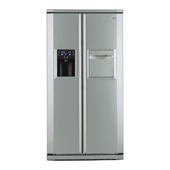
SIDE BY SIDE RSE8KPAS RSE8KPAS1/ XEU REFRIGERATOR PRODUCT FEATURE Twin Cooling System Cool Select Zone & Chilled Compartment Spill-proof Shelf & Safety Glass Shelf Automatic Wator And Ice Dispenser For more information, Please access to our service web site (http://itself.sec.samsung.co.kr) -
Page 2: Important Safety Notice
The manufacturer or dealer cannot be responsible for the interpretation of this information. SAMSUNG ELECTRONICS AMERICA, INC. Technical Service Guide Copyright ⓒ2005 All rights reserved. This service guide may not be reproduced in whole or in part in any form without written permission from the SAMSUNG ELECTRONICS Company. -
Page 3: Table Of Contents
Contents 1. PRECAUTIONS (SAFETY WARNINGS) ∙∙∙∙∙∙∙∙∙∙∙∙∙∙∙∙∙∙∙∙∙∙∙ 2. PRODUCT SPECIFICATIONS ∙∙∙∙∙∙∙∙∙∙∙∙∙∙∙∙∙∙∙∙∙∙∙∙∙∙∙∙∙ 3. OPERATING INSTRUCTIONS & INSTALLATION ∙∙∙∙∙∙∙∙∙∙∙∙∙∙∙∙∙∙ 4. ALIGNMENT AND ADJUSTMENTS ∙∙∙∙∙∙∙∙∙∙∙∙∙∙∙∙∙∙∙∙∙∙∙∙∙∙ 5. DISASSEMBLY AND REASSEMBLY ∙∙∙∙∙∙∙∙∙∙∙∙∙∙∙∙∙∙∙∙∙∙∙∙∙ 6. TROUBLESHOOTING ∙∙∙∙∙∙∙∙∙∙∙∙∙∙∙∙∙∙∙∙∙∙∙∙∙∙∙∙∙∙∙∙∙∙ 7. EXPLODED VIEW & PARTS LIST ∙∙∙∙∙∙∙∙∙∙∙∙∙∙∙∙∙∙∙∙∙∙∙∙∙∙∙ 8. BLOCK DIAGRAM ∙∙∙∙∙∙∙∙∙∙∙∙∙∙∙∙∙∙∙∙∙∙∙∙∙∙∙∙∙∙∙∙∙∙∙∙ 9. -
Page 4: Precautions(Safety Warnings)
1. Precautions(Safety Warnings) ●Unplug the refrigerator before making any repair or any replacement. � Avoid electric shock. ●Use the rated components on the replacement. � Check the correct model number, rated voltage, rated current, operating temperature and so ●On repair, be sure that the wires such as harness are bundled tightly and are not exposed by water. - Page 5 Precautions(Safety Warnings) Read all instructions before repairing the product and keep to the instructions in order to prevent danger or property damage. CAUTION/WARNING SYMBOLS DISPLAYED SYMBOLS means “Prohibition”. Indicates that a danger of death means “Do not disassemble”. Warning or serious injury exists.
- Page 6 Precautions(Safety Warnings) Please ler users know following warnings & cautions in detail. Warning & Caution Do not allow users to store Do not allow users to store narrow Do not allow users to put bottles or and lengthy bottles or foods in a pharmaceutical products, scientific kinds of glass in the freezer.
-
Page 7: Product Specifications
2. Product Specifications 2-1) Introduction of main function SAMSUNG side by side refrigerator has the following characteristics. ● ● Beverage Station (optional) Twin Cooling System • The refrigerator and the freezer have two • You do not have to open the main door to access evapora tors. - Page 8 Product Specifications 2-2) Model Specification Item Specification RSE8J*, D* RSE8K*, F*, V*, T* M M o o d d e e l l ( ( R R S S E E 8 8 ) ) Dispenser Dispenser without home-bar with home-bar T T o o t t a a l l 510l 495l...
- Page 9 Product Specifications 2-4) Electric Parts Specification Items Specification Models Freezing Capacity (4 STAR) Model MK4A5Q-R1U Compressor Starting type R.S.C.R FREOL α - 15 (ESTER) Oil Charge Freezer SPLIT FIN TYPE Evaporator Refrigerator SPLIT FIN TYPE Condenser Forced and natural convection type Dryer Molecular sieve XH-9 0.82×3400, 5.5 Kg/cm 2...
-
Page 10: Specifications
Product Specifications Specifications Items Model Dispenser Home Bar Defrost-Heater(FRE) Conducting at F Defrosting 245W Defrost-Heater(REF) Conducting at R Defrosting 110 W DRAIN Heater(FRE) Conducting at F Defrosting 45 W 25 W DRAIN Heater(REF) Conducting at R Defrosting DISPENSER Heater Interlock with F-FAN HOME-BAR Heater Interlock with COMP WATER PIPE Heater... - Page 11 Product Specifications 2-5) Dimensions (mm)
- Page 12 Product Specifications 2-6) Optional Material Specification Photographe Part Name Part Code Remark FILTER DA29-00003B WATER-ASSY ASSY-INSTALL DA97-01469D FILTER Freezer : 2pcs LAMP INCANDENT 4713-001201 230V, 40W Refrigerator : 5pcs LAMP INCANDENT 4713-001147 240V, 25W...
-
Page 13: Operating Instructions & Installation
3. Operating Instructions & Installation 3-1) Digital Panel ∙∙∙∙∙∙∙∙∙∙∙∙∙∙∙∙∙∙∙∙∙∙∙∙∙∙∙∙∙∙∙∙∙∙∙∙∙∙ 3-2) Temperature Control Function ∙∙∙∙∙∙∙∙∙∙∙∙∙∙∙∙∙∙∙∙∙∙∙∙∙∙∙∙ 3-3) Power Freeze and Vacation Function ∙∙∙∙∙∙∙∙∙∙∙∙∙∙∙∙∙∙∙∙∙∙∙∙ 3-4) Child Lock Function ∙∙∙∙∙∙∙∙∙∙∙∙∙∙∙∙∙∙∙∙∙∙∙∙∙∙∙∙∙∙∙∙∙∙ 3-5) Function with Ice Dispenser &Water Dispenser Installed ∙∙∙∙∙∙∙∙∙∙∙∙∙ 3-6) C-Fan Motor Delay Function of the Machine Compartment ∙∙∙∙∙∙∙∙∙∙∙... -
Page 14: 3-1) Digital Panel
Operating Instructions & Installation 3-1) Digital Panel for RSE8F,D,N*** for RSE8K,J,V,T*** 3-2) Temperature Control Function When the system power is initally engaged, the default set temperature are -20℃ for the freezer and 3℃ for the refrigerator, respectively. The numbers shown on the digital display panel stand for the actual compartments temperatures. -
Page 15: 3-3) Power Freeze And Vacation Function
Operating Instructions & Installation 3-3) Power Freeze and Vacation Function Select the “Power Freeze” button. Although you select Power Freezer, the set temperatures in the freezer is not changed. The set temperatures for the compartments can be changed while this function is in use. 1) Power Freeze function 1-1) When you press the Power Freeze button, the LED indicator lights right away, but there is 10 seconds lag time to an actual operation. -
Page 16: 3-5) Function With Ice Dispenser &Water Dispenser Installed
Operating Instructions & Installation 3-5) Function with Ice Dispenser &Water Dispenser Installed This function only applies to the model with Ice Maker and Ice/Water Dispenser. 1) Water / Cubed Ice / Crushed Ice / Ice Off Select Function 1-1) By pressing each specific button on the display panel, Water, Cubed Ice, Crushed Ice, Ice Off will be selected. But, the Ice Off button needs to be pressed for more than 3 seconds to select. -
Page 17: 3-8) Water Filter Indicator Function
Operating Instructions & Installation 1) Select function 1-1) Using Select button, Soft Freeze (-5℃), 0 Zone(0℃), Quick Cool, Cool, Thaw options can be selected in sequence. Cool option maintains a set temperature of the refrigerator. 1-2) Temperature control for fresh food compartment is ahead of cool select Zone. 2) Quick Cool function 2-1) If the Quick Cool is selected, LEDs will flash 60 Min. -
Page 18: 3-9) Ice-Maker Function
Operating Instructions & Installation 3-9) Ice-Maker Function The Ice-maker is referred to the device with an automatic ice production, storage in the ice bucket and dispensing through the ice chute. 1) Preparation of Ice-maker 1-1) Connect the water line to the water supply valve of refrigerator to supply water. (See how to connect a water supply line in the owner’s manual.) 1-2) Push the bucket back fully so that the guide-ice of ice maker should not touch the back of bucket. - Page 19 Operating Instructions & Installation 3) Water Supply function 3-1) When the ice tray is levelled again after ejecting ice, the water solenoid valve will be controlled to supply water. - The ice eject standby time is as follows.(With ice full,it stands by for an hour) Detection of Water Supply Detection of No Water Supply No.of...
-
Page 20: 3-10) Defrost Function
Operating Instructions & Installation 9-1) 1 Step : It is an ice temperature checking step for ice ejection. It checks whether the ice temperature is lower than - 17.0 ℃ and it has passed 58 mins (58~110 mins : refere to table 3-1) after water supply. - When F-Defrost goes into operation during the ice eject standby, it will be counted from the start after the completion of Defrost and it will be checked if it has passed 58 minutes after the completion of F-Defrost. -
Page 21: 3-11) Sound Function
Operating Instructions & Installation 3-11) Sound Function 1) Button Touch Tone (Refer to Sound Table) 1-1) When selecting each button on the Control Panel, Button Touch Tone goes off as follows. Sound Group Sound Pattern Description SUB ON Selection of POWER FREEZE, VACATION,LOCK,ICE OFF or (Function Selection) FILTR RESET SUB OFF... -
Page 22: Alignment And Adjustments
4. Alignment and Adjustments 4-1) Forced Operation Function (Pull-down / Refrigerator Defrost / Refrigerator . Freezer-Defrost / Cancellation) ∙ 4-2) Self-Diagnostics Function ∙∙∙∙∙∙∙∙∙∙∙∙∙∙∙∙∙∙∙∙∙∙∙∙∙∙∙∙∙∙ 4-3) Load Operation Check Function ∙∙∙∙∙∙∙∙∙∙∙∙∙∙∙∙∙∙∙∙∙∙∙∙∙∙∙ 4-4) Restoration Function for Power Outage ∙∙∙∙∙∙∙∙∙∙∙∙∙∙∙∙∙∙∙∙∙∙∙ 4-5) Set Point Shift Function ∙∙∙∙∙∙∙∙∙∙∙∙∙∙∙∙∙∙∙∙∙∙∙∙∙∙∙∙∙∙∙∙... -
Page 23: 4-1) Forced Operation Function (Pull-Down / Refrigerator Defrost / Refrigerator . Freezer-Defrost / Cancellation)
Alignment and Adjustments 4-1) Forced Operation Function (Pull-down / Refrigerator Defrost / Refrigerator . Freezer-Defrost / Cancellation) This function enables a pull-down mode, a defrost mode for the refrigerator only, a defrost mode for the freezer and the refrigerator at the same time, and a cancellation of this function. Press fridge and Power Freeze. - Page 24 Alignment and Adjustments � Self-diagnostics check list Error ① ICE MAKER SENSOR ② REFRIGERATOR SENSOR ③ REFRIGERATOR DEFROST SENSOR ④ REFRIGERATOR FAN ERROR ⑤ ICE MAKER function error ⑥ CoolSelect Zone SENSOR ⑦ REFRIGERATOR DEFROST ERROR ⑧ EXIT-SENSOR ⑨ FREEZER SENSOR ⑩...
-
Page 25: 4-3) Load Operation Check Function
Alignment and Adjustments 4-3) Load Operation Check Function 1) In the normal operation, press Power Freeze and Vacation buttons simultaneously for 6 second, then the display panel will blink for 2 seconds. 2) Press Fridge Temp. button ⓐ to get into this check mode with an audible tone. 3) Each illuminating LED segment stands for the component which has an ouput signal from the control board. -
Page 26: 4-6) Table Of Set Point Shift Function
Alignment and Adjustments 1) Initially, all products set the code, “0” 2) After 20 seconds from adjustment, a new setting will be stored in EEPROM and return to the normal display. 3) Freezer Temp, Fridge Temp., Ice maker water supply, Ice tray temperature, and CoolSelect Zone temperature can be adjusted with this function. - Page 27 Alignment and Adjustments Example) If you are lowering the current temperature of the freezer by - 3 ℃ 2) Shift the refrigerator temperature sensor Reference Value Code Code Temp. shift Temp. shift 0.5 ℃ - 0.5 ℃ 1.0 ℃ - 1.0 ℃ 1.5 ℃...
- Page 28 Alignment and Adjustments ■The following options is limited to a model with the Ice Maker. 5) Shift the CoolSelect Zone temperature sensor. 3) Adjust the volume to supply water for the ice maker Reference Value Reference Value CoolSelect Zone Code Volume to supply water Code temperature sensor...
-
Page 29: Disassembly And Reassembly
5. Disassembly and Reassembly 5-1) Assy Door 5-2) Door Sub Parts Control Panel ∙∙∙∙∙∙∙∙∙∙∙∙∙∙∙∙∙∙∙∙∙∙∙∙∙∙∙∙∙∙∙∙∙∙∙∙∙∙∙∙ Door Handle ∙∙∙∙∙∙∙∙∙∙∙∙∙∙∙∙∙∙∙∙∙∙∙∙∙∙∙∙∙∙∙∙∙∙∙∙∙∙∙∙ Beverage Station ∙∙∙∙∙∙∙∙∙∙∙∙∙∙∙∙∙∙∙∙∙∙∙∙∙∙∙∙∙∙∙∙∙∙∙∙∙ Door Gasket ∙∙∙∙∙∙∙∙∙∙∙∙∙∙∙∙∙∙∙∙∙∙∙∙∙∙∙∙∙∙∙∙∙∙∙∙∙∙∙∙∙ 5-3) Refrigerator Compartments Refrigerator Door Light Switch ∙∙∙∙∙∙∙∙∙∙∙∙∙∙∙∙∙∙∙∙∙∙∙∙∙∙∙∙∙∙ Refrigerator Light ∙∙∙∙∙∙∙∙∙∙∙∙∙∙∙∙∙∙∙∙∙∙∙∙∙∙∙∙∙∙∙∙∙∙∙∙∙∙ Tempered Glass Shelf ∙∙∙∙∙∙∙∙∙∙∙∙∙∙∙∙∙∙∙∙∙∙∙∙∙∙∙∙∙∙∙∙∙∙∙ Plastic Drawers in Refrigerator ∙∙∙∙∙∙∙∙∙∙∙∙∙∙∙∙∙∙∙∙∙∙∙∙∙∙∙∙∙∙... -
Page 30: Removing The Front Leg Cover
Disassembly and Reassembly 5-1) Assy Door Removing the Front Leg Cover Open the freezer and refrigerator doors, and then take off the front leg cover assembly by turning the three screws counter-clockwise. FRONT LEG COVER SCREW Separating the water supply line from the refrigerator 1) Remove the water tube by pressing the coupler ( ) and pulling the water tube ( ) away. -
Page 31: Removing The Freezer Door
Disassembly and Reassembly • Lift the door straight up. • Be careful not to pinch the water tubing and wire harness on the door. NOTE • Place doors on a protected surface. Removing the Freezer Door 1) With the door closed, remove the Top table ( ) using a screwdriver, and then disconnect the wires ( ). - Page 32 Disassembly and Reassembly Removing the Refrigerator Door 1) Disconnect the wires ( ). 2) Remove hinge screws ( ) and ground screw ( ) counter-clockwise, and take off the upper hinge ( ) in the direction of the arrow ( ). Take care when removing the door to ensure that it does not fall on you. 3) Remove the door from the lower hinge ( ) by 4) Remove the lower hinge ( ) from the bracket lifting the door ( ).
- Page 33 Disassembly and Reassembly Reattaching the Freezer Door 1) Reattach the freezer door by inserting the hose ( ) in the lower side of the door into the hole in the lower hinge ( ) and pull the hose down. 2) Insert the upper hinge shaft ( ) into the hole ( ). After levelling the upper hinge hole ( ) with the hole of the cabinet ( ).
- Page 34 Disassembly and Reassembly Reattaching the Refrigerator Door 1) Insert the lower hinge ( ) in the bracket 2) Place the hole in the refrigerator door ( ) lower hinge ( ). over the lower hinge ( ). 3) Insert the upper hinge shaft ( ) into the hole ( ). After levelling the upper hinge hole ( ) with the hole of the cabinet ( ).
-
Page 35: 5-2) Door Sub Parts
Disassembly and Reassembly 5-2) Door Sub Parts Control Panel Beverage Station The beverage station allows access to the 1. Insert a flat-blade screwdriver on the slot as shown, refrigerator without opening the refrigerator door. and unlock the tabs. 1. Open the door beverage station 2. -
Page 36: 5-3) Refrigerator Compartments
Disassembly and Reassembly 5-3) Refrigerator Compartments Refrigerator Door Light Switch Tempered Glass Shelf The refrigerator has a door light switch located in These shelves allow the storage of larger items and the upper right corner for the refrigerator. pull out for easy access. 1. -
Page 37: Water Filter
Disassembly and Reassembly Water Filter Upper Ductwork The water filter is located in the upper right-hand 1. Remove the screw caps (2) and screws (5). corner of the refrigerator. The water filter filters water 2. Slide the upper fan ductwork out while for the ice maker and the water dispenser. -
Page 38: Evaporator In Refrigerator
Disassembly and Reassembly Evaporator in Refrigerator Refrigerator Thermistor Refrigerator Thermistor Evaporator is located in the bottom of refrigerator. 1. Take off the ductwork in refrigerator. The refrigerator thermistor is located inside of the 2. Disconnect the wire connector.(Heater and upper light cover of the refrigerator. Thermistor) Thermistor 3. -
Page 39: Door Bin In Freezer
Disassembly and Reassembly 5-4) Freezer Compartments Door Bin in Freezer Plastic Drawer in Freezer Drawers are designed for storage of meat and dry The door bins allow storage of perishable items. foods. The drawers are located in the lower portion of 1. -
Page 40: Ice Dispenser & Ice Maker
Disassembly and Reassembly 2. Lift the front locking tab and assemble the ice Ice Dispenser & & Ice Maker maker kit. The ice dispenser is located in the upper portion of 3. Connect the ice maker wire connector. the freezer. This assembly stores ice made by the 4. -
Page 41: Freezer Light
Disassembly and Reassembly Freezer Light Upper Ductwork The freezer light is located in the bottom of the 1. Remove the screw cap and screw. auger motor case. The light is covered by an opaque 2. Slide the upper fan ductwork out while cover. -
Page 42: Evaporator In Freezer
Disassembly and Reassembly Evaporator in Freezer Evaporator is located in the bottom of freezer to produce cold air driven across the evaporator coils. 1. Take off the ductwork in Freezer. 2. Disconnect the wire connector (Heater, Bimental, and Thermistor). 3. Desolder the inlet and outlet tubes. 4. -
Page 43: 5-5) Machine Compartments
Disassembly and Reassembly 5-5) Machine Compartments 3. Disconnect water tubes (3). Machine Compartment & & Electric Box 1. Disconnect the power cord of the refrigerator. 2. Remove the fixed screws (6) of compressor cover. Condenser Fan 3. Slide up and take off the compressor cover to see the machine compartment. -
Page 44: Troubleshooting
6. Troubleshooting 6-1) If power is not ON Caution! To check the main PCB, please apply At the power of main PCB, the 230V power and a high-voltage over about descriptions of operation and DC 320V occur. Please take care of yourself on repair and measurement. references in the manual. - Page 45 Troubleshooting 6-2) If the compressor and cooling fan motor don’t work normally Start Did 5 min pass after COMP. OFF? Check after a lapse of 5 min. Does compressor work with forced operation? Did buzzer sound on forced operation? (Check certainly after forced start.) Is freezer sensor normal? Is MICOM No.37 High?(5V) Open and repair the...
- Page 46 Troubleshooting 6-3) If defrost function Start Is F, R defrosting sensor by self-diagnosis normal? Exchange and troubleshoot the corresponding sensor. Is F, R Room defrosting heater normal? � Refer to the descripton of Circuit operation in Check temp. fuse, breaking of heater wire, contact of the manual 10-4) door S/W sensing Circuit.
- Page 47 Troubleshooting 6-4) If there is a trouble with self-diagnosis - Error of sensor can be seen on the front display of refrigerator. If power is impressed to refrigerator first, an failure of sensor is found. The refrigerator will stop working and display(blink) the region of trouble-occurred sensor repetitively. - Even if sensor has failure during the operation, the refrigerator will not stop working but can run the normal cooling operation because of being operated in the Emergency Operation mode.
- Page 48 Troubleshooting 6-5) If alarm sound 1) If “Ding-Dong” sounds continuously Start Isn’t the door opened minutely? Remove causes after comprehending the conditions of interference by door gasket, food etc. Isn’t water penetrated into the door S/W? Exchange the door S/W. �...
- Page 49 Troubleshooting 3) Without sound of buzzer operation Start Does it sound ‘Ding-Dong’if you press a button on front panel? Main PCB is normal; buzzer normal. Does i t make a sound of ‘ d oor-open’ al a rm when you are openi n g the door of freezer or fri d ge more than 2 mi n ? Check the panel PCB with the reference of ‘how to check panel...
- Page 50 Troubleshooting 6-6) If the panel PCB is not working normally: 1) Where lighting of the panel PCB is disabled, or only some lamps are disabled. Start Is the connector � See Ref. 1: ‘View of the of upper hinge cover inserted connection cabinet-door normally? for the wire assembly’...
- Page 51 Troubleshooting 6-7) If fan doesn’t work: Reference � R room Fan is AC motor used. The BLDC motor is driven by DC 8-12V. � Under the normal condition of COMP ON, it is operated together with F-FAN motor. With operation of the CoolSelect Zone function, the F-Fan motor may do not work.
- Page 52 Troubleshooting 6-8) If CoolSelect Zone isn’t operated normally 1) If the lamp of CoolSelect Zone is not lighten. Start Is the connector of CoolSelect Zone inserted correctly in the refrigerator? Reinsert the connector; troubleshoot a bad contact. Is the connector of main PCB (CN51) inserted correctly? Reinsert the connector in the main PCB.
- Page 53 Troubleshooting 6-9) If the lamps of freezer / refrigerator does not light. Caution! 1. When you are exchanging the lamp of freezer, please exchange or troubleshoot it with the power OFF to avoid an electric shock. 2. Please keep in mind you do not get burnt by the excessive heating of an incandescent light bulb. Start Is the inside lamp filament cut? Exchange or troubleshoot the...
- Page 54 Troubleshooting 6-10) When the Dispenser Cover does not close Note 1) When the Dispenser S/W is pressed after selecting the type of ice (CUBED or CRUSHED), the Geared Motor will operate and the Dispenser Cover will be opened. When the button keeps on being pressed, ice comes out. If the Geared Motor does not operate, check the Dispenser S/W first.
- Page 55 Troubleshooting 6-11) If Crushed Ice/Cubed Ice doesn’t work properly: The close condition on operation Start is subject to the freezer door. Is ice ejected? Does ice in the ice tray exist ? 1) Check the ice-ejector S/W. Do you see Ice Stop on the digital panel? 2) Check the door S/W.
-
Page 56: Exploded View & Parts List
7 . Exploded View & Parts List 7-1) Freezer 2-23 2-25 11-1 2-22 2-20 2-19 2-17 11-1 2-16 2-15 2-14 2-10 2-13 2-12 2-11 12-1 2-26 2-27 12-1 6-10 6-11 14-1 15-2 15-1... - Page 57 Exploded View & Parts List ■ ■ Parts List of Freezer CODE-NO PART NAME Spec Quantity Remark DA97-02641A ASSY-SUPPORT ICE MAKER 230V/50Hz DA61-02057A SUPPORT-ICE MAKER RS18RK,HIPS,WHT DA63-02284A TRAY ICE AD,PP,SC-93437R,BJ73SL DA61-01800A FIXER-SENSOR(ICE MAKER) AD,URETHANE DA63-02183A COVER-SENSOR AD,PP,T1.0,WHITE DA59-00294A ICE MAKER-ASSY NTGN,DC12V DA61-00954A GUIDE-ICE FULL...
- Page 58 Exploded View & Parts List ■ ■ Parts List of Freezer CODE-NO PART NAME Spec Quantity Remark DA31-00118A MOTOR DC-BLDC DL-5905SSEA,EPEL,3.0W, DA63-01809A COVER MOTOR-BLDC BLDC-NEW,PP(BJ-730),NTR 6-10 6002-001341 SCREW-TAPPING BH,+,1,M4,L16,DAC(WHT),S 6-11 DA63-01146A GROMMET-MOTOR A-TOP,NBR,ID6.5,OD42 DA97-02647A ASSY EVAP-FRE RS18RK,230/50 DA32-10105R SENSOR ASSY-FRE 502AT,ET-PJT50~50,5V,1 DA47-10148K THERMO FUSE-ASSY,B...
- Page 59 Exploded View & Parts List 7-2) Refrigerator 14-1 14-2 15-8 15-4 15-5 2-8-1 15-6 2-8-2 2-8-3 15-7 15-12 15-10 15-3 15-2 15-11 3-12 3-13 3-11 3-10 17-1 18-2 18-1...
- Page 60 Exploded View & Parts List ■ ■ Parts List of Refrigerator CODE-NO PART NAME Spec Quantity Remark DA34-10110E SWITCH DOOR-R Sliding,250V,0.5A DA97-02653A ASSY COVER-MULTI,REF EPEL,PP,W DA47-00069H LAMP HOLDER-MULTI REF 250V,75W,Cu,PBT,HOLDER 4EA DA96-00173A ASSY-HARNESS LAMP E-PEL,WIRE-HARNESS MAIN,A DA32-10109Y SENSOR ASSY 502AT,A-TOP,5V,R-SENSO DA67-01168A CAP-SENSOR,REF EPEL,PP,T2.0,W130.5,WHT...
- Page 61 Exploded View & Parts List ■ ■ Parts List of Refrigerator CODE-NO PART NAME Spec Quantity Remark 15-6 DA41-00270A PBA DISPLAY-(C-ROOM) E-PEL,PBA_C-ROOM,FR-1,1.6*28*212.5 15-7 6002-000630 SCREW-TAPPING PH,+,2S,M3,L8,ZPC(YEL),SWRCH18A 15-8 DA64-01494A INLAY-CONVERTIBLE EPEL,PC,T0.25,W42.5,L1 15-9 DA97-02628A ASSY TRAY-CONVERTIBLE RS18RK 15-10 DA66-00148A ROLLER A-TOP,POM,Φ16,SC-93437R,P 15-11 6009-001278 SCREW-SPECIAL TWH,+,M4,L9(6),PASS,STS3...
- Page 62 Exploded View & Parts List 7-3) Cabinet 20-2 20-2 20-1 Purifier Water line Valve water fitting 22-3 22-2 Sealing tape Tapping screw x 12EA Clip A x 12EA 22-5 (Connector Water Filter Assy) 22-4 22-1...
- Page 63 Illustrated Parts Catalog. ■ ■ Parts List of Cabinet CODE-NO PART NAME Spec Quantity Remark 6006-001108 SCREW-TAPPING PW(OD15),TH,+,M4,L16,ZPC(Y DA64-01449A EPEL,ABS,W408.0,L171.5,AL SILVER,SC-01014S DA64-01449B TOP TABLE-SIDE,L RS18RK,ABS,SC-05010S(P/S DA64-01449C RS18RK,ABS,SC-05013S,CORAL-WHT DA64-01450A EPEL,ABS,W408.0,L171.5,AL SILVER,SC-01014S DA64-01450B TOP TABLE-SIDE,R RS18RK,ABS,SC-05010S(P/S DA64-01450C RS18RK,ABS,SC-05013S,CORAL-WHT DA97-02630A EPEL,ABS,W943.0,L253.0,AL SILVER,SC-01014S DA97-02630B ASSY TOP TABLE ABS,SC-05010S,PLATINUM SILVER DA97-02630C...
- Page 64 Exploded View & Parts List 7-4) Cabinet 21-8 21-1 21-3 21-2 21-4 21-5 21-7 21-6...
- Page 65 Illustrated Parts Catalog. ■ ■ Parts List of Cycle CODE-NO PART NAME Spec Quantity Remark DA97-00708F ASSY PIPE-WATER ICE EPEL,230V/5W DA97-02858A ASSY COVER-TUBE WATER EPEL,W161.5,L66.0 6006-001108 SCREW-TAPPING PW(OD15),TH,+,M4,L16,ZPC(Y DA63-00586A COVER-TUBE FILTER ZIPEL,PP,T2.0,SC DA97-02644A ASSY COVER-FIXER WATER LINE RS18RK,W43,L58 6502-000112 CABLE CLAMP DA-8N,ID13.2,T1.0,NYLON6/6,N DA97-02681A ASSY COVER-COMP...
- Page 66 Exploded View & Parts List 7-5) Disassembly of Freeze Door 21-1 21-2 21-5 21-3 21-6 21-4...
- Page 67 Illustrated Parts Catalog. ■ ■ Parts List of Freezer Door CODE-NO PART NAME Spec Quantity Remark DA91-02003A SC-05014TP,AL SILVER,-,-,DISP TYPE DA91-02003B ASSY DOOR FOAM FRE SC-05010TE,N,-,-,PLATINUM SILVER DA91-02003C EPEL,SC-05013TV,N,-,-,WHT CORAL DA97-01800S ASSY-GASKET DOOR,FRE EPEL,W384,L1670.0 DA97-02635A ASSY GUARD-FRE LOW RS18RK,ABS,WHT DA61-02085A STOPPER-DOOR RS18RK,SHP1,T3.0,W35.0,L77 DA66-00344A...
- Page 68 Exploded View & Parts List 7-6) Disassembly of Refrigerator Door 18-1 18-3 11-1 11-2...
- Page 69 Illustrated Parts Catalog. ■ ■ Parts List of Refrigerator Door CODE-NO PART NAME Spec Quanti t y Remark DA91-02004A SC-05014TP,AL SILVER,-,-,DISP TYPE DA91-02004B ASSY DOOR FOAM REF EPEL,SC-05010TE,PLATINUM SILVER DA91-02004C EPEL,SC-05013TV,WHT CORAL DA97-01800T ASSY-GASKET DOOR,REF EPEL,W457 x L1670,S DA63-02442A COVER-DAIRY EPEL,GPPS,W359.5,L87.0,H124 DA63-02440A GUARD-DAIRY...
-
Page 70: Block Diagram
8 . Block Diagram... -
Page 71: Wiring Diagram
9 . Wiring Diagram... -
Page 72: Pcb Diagram
10. PCB Diagram 10-1) PART ARRANGEMENT (Main Board) ① ② ⑬ ③ ⑭ ④ ⑫ ⑤ ⑥ ⑮ ⑪ ⑩ ⑨ ⑧ ⑦ 1. Available FOR NORMAL COMPRESSOR DC12V,5V,GNDSUPPLY THROUGH CN75 FOR Inverter, COMPRESSOR. 2. FAN MOTOR DRIVING PART POWER SUPPLIED FROM 8. 3V TO10V ACCORDI NGTOMOTORVOLTS. 3. - Page 73 PCB Diagram 10-2) CONNECTOR ARRANGEMENT (Main Board)
-
Page 74: Circuit (Schematic) Diagram
11. Circuit (Schematic) Diagram... -
Page 75: Circuit Descriptions
12. Circuit Descriptions 12-1) Source Power Circuit ∙∙∙∙∙∙∙∙∙∙∙∙∙∙∙∙∙∙∙∙∙∙∙∙∙∙∙∙∙∙∙∙ 12-2) Oscillator Circuit ∙∙∙∙∙∙∙∙∙∙∙∙∙∙∙∙∙∙∙∙∙∙∙∙∙∙∙∙∙∙∙∙∙∙∙ 12-3) Reset Circuit ∙∙∙∙∙∙∙∙∙∙∙∙∙∙∙∙∙∙∙∙∙∙∙∙∙∙∙∙∙∙∙∙∙∙∙∙∙ 12-4) Door S/W Sensing Circuit ∙∙∙∙∙∙∙∙∙∙∙∙∙∙∙∙∙∙∙∙∙∙∙∙∙∙∙∙∙∙ 12-5) Temperature Sensing Circuit ∙∙∙∙∙∙∙∙∙∙∙∙∙∙∙∙∙∙∙∙∙∙∙∙∙∙∙∙ 12-6) Key Scan and Display Circuit ∙∙∙∙∙∙∙∙∙∙∙∙∙∙∙∙∙∙∙∙∙∙∙∙∙∙∙∙ 12-7) CoolSelect Zone Panel Circuit ∙∙∙∙∙∙∙∙∙∙∙∙∙∙∙∙∙∙∙∙∙∙∙∙∙∙ 12-8) Fan Motor(BLDC) Drive Circuit ∙∙∙∙∙∙∙∙∙∙∙∙∙∙∙∙∙∙∙∙∙∙∙∙∙∙∙... -
Page 76: 12-1) Source Power Circuit
Circuit Descriptions 12-1) Source Power Circuit This circuit shows SMPS(Switch Mode Power Supply) which converts AC input voltage (230V, 50Hz) to a high DC voltage (340V). The input AC source power is converted to DC through a wave rectifier (BD1) and the converted DC power will generate a constant waveform on the switching transformer using a high speed (100KHz) switching motion of TOP223Y. -
Page 77: 12-4) Door S/W Sensing Circuit
Circuit Descriptions 12-4) Door S/W Sensing Circuit - DOOR PARTS FUNTION - SENSOR PARTS FUNTION Terminal Operation Volt(state) Terminal No Remark F-SENSOR (51) DOOR OPEN 5V (HIGH) Freezer Micom terminal F-DEF-SENSOR (52) (No.31) DOOR CLOSE 0.7V (LOW) voltage may R-SENSOR (53) change DOOR OPEN 5V (HIGH) -
Page 78: 12-5) Temperature Sensing Circuit
Circuit Descriptions 12-5) Temperature Sensing Circuit 1) A thermistor with a negative temperature coefficient (NTC) is used for a temperature sensor. This devided 2) Resistors, R 303 � R312 and capacitors, C 302 � C 306 are used for voltage is detected by MICOM a noise protection purpose. -
Page 79: 12-6) Key Scan And Display Circuit
Circuit Descriptions 12-6) Key Scan and Display Circuit 1) Key Scan and display operation. The model uses a decorder IC which 4 inputs and 9 outputs. If the IC 9 decorder (TC4028BP) receivesd signals from MICOM pins (3�6), an output signal per 2 miliseconds comes out from Q3, Q41, Q8, Q6, Q9, Q7, Q0, Q2, and Q4 pin in sequence. - Page 80 Circuit Descriptions The step signals of DC 11~2V will be generated periodically. If a sink signal outputs from IC4, DC 11-12V will be applied to the LED input terminal and sink the LED output terminal to 0V. Therefore, LED will be ON for 2 miliseconds. 2) Key Scan The 6 step signals, Q6~Q4 are applied to scan the 6 keys (buttons).
-
Page 81: 12-7) Coolselect Zone
Circuit Descriptions 12-7) CoolSelect Zone Panel Circuit 1) CoolSelect Zone display panel and temperature sensor, Lamp PCB 1-1) CoolSelect Zone is referred to as a storage drawer to implement features of Soft Freeze, 0 Zone, Quick cool, Cool and Thaw 1-2) CoolSelect Zone has an additional display panel.Panel LED are off while the doors are closed.When a door is opened,micro-processor senses its signal and LEDs will be on. -
Page 82: 12-8) Fan Motor(Bldc) Drive Circuit
Circuit Descriptions 2-1) CoolSelect ZoneTM Drawer is controlled by a damper to supply or block cold air. For Quick Cool, the damper will be closed. So cold air is supplied only to CoolSelect ZoneTM Drawer.For Thaw, the evaporator heater of refrigerator is ON and the damper is controlled by the refrigerator temperature. -
Page 83: 12-9) Eeprom Circuit
Circuit Descriptions 1-4) When there is error in the motor (if the motor is sensed under 600 ~ 700 RPM), the relevant motor stops immediately and it tries to start up in 10 seconds. At this time, when the RPM is sensed as normal, the motor will be judged as normal and it starts operating. -
Page 84: 12-11) Load Drive Circuit
Circuit Descriptions 12-11) Load Drive Circuit 1) The control of load in the system is accomplished by the main PCB. 2) Most of relays or SSRs can control the compressor, refrigerator/freezer defrost heater, and several option functions. 3) For the compressor, #37 pin of micro processor signals High (5V). This signal enters #8 pin of IC73 and #11 of output terminal which have base and collector functions of IC73 turns on and connects the GND. -
Page 85: Reference Information
J : With Dispenser and Convertible K : With Dispenser,Home-bar and Convertible V : With Dispenser and Convertible (Inverter Compresor) T : K-option + Transparent Home-bar CATEGORY S : SBS VOLUME CAPACITY : E8 (18 cu.ft) BRAND : R-SAMSUNG REFRIGERATOR B-OEM REFRIGERATOR Label Location... - Page 86 Reference Information 13-2) Q & A Possible Causes What To Do Problem • Disconnected power plug • Check that the power plug is properly The refrigerator does not connected. work sufficiently or at all • Is the temperature control on the display •...
- Page 87 Reference Information Problem Possible Causes What To Do Small or hollow cubes Water filter clogged. • Replace filter cartridge with new cartridge or with plug. Door left open. • Check to see if package is holding door open. Temperature control not set •...
- Page 88 Reference Information 13-3) Additional Information Compressor → Sub-condenser → Hot Pipe → Dryer → Capillary Tube → Refrigerator Evaporator → Freezer Evaporator→ Suction Pipe → Compressor Refrigerator Evaporator ACCUMULATOR Freezer Evaporator Dryer Hot Pipe SUCTION PIPE SUB-CONDENSER Capillary Tube Compressor Muffler Hot Pipe...
- Page 89 Reference Information Freezer Refrigerator...
- Page 90 Gwangju-City, Korea, 506-253 TEL : 82-62-950-6193, 6896 FAX : 82-62-950-6829 - This Service Manual is a property of Samsung Electronics Co., Ltd. Any unauthorized use of Manual can be punished under applicable International or domestic law. - © Samsung Electronics Co., Ltd.