
Related Manuals for GE On-line VH Series


Summary of Contents for GE On-line VH Series
-
Page 1: User Manual
Critical Power User Manual Uninterruptible Power Supply GE Consumer & Industrial SA General Electric Company CH – 6595 Riazzino (Locarno) Switzerland T +41 (0)91 / 850 51 51 F +41 (0)91 / 850 52 52 www.gecriticalpower.com... - Page 2 © General Electric Consumer & Industrial SA. All rights reserved. The present publication and any other documentation supplied with the UPS system is not to be reproduced, either in part or in its entirety, without the prior written consent of GE.
-
Page 3: Table Of Contents
Critical Power Contents IMPORTANT SAFETY INSTRUCTIONS ......................4 SAVE THESE INSTRUCTIONS ..................................4 SAFETY WARNINGS AND SYMBOLS................................4 SAFETY RULES ........................................5 TRANSPORT / STORAGE ....................................5 FCC COMPLIANCE STATEMENT ..................................5 INTRODUCTION ..............................6 INTRODUCTION ........................................6 INTENDED USE ........................................6 WARRANTY.......................................... -
Page 4: Important Safety Instructions
The UPS is not suitable for computer room application as per the standard NFPA75. While every care has been taken to ensure the completeness and accuracy of this manual, GE accepts no responsibility or liability for any loss or damage resulting from the use of the information contained in this document. -
Page 5: Safety Rules
Critical Power SAFETY RULES CAUTION! RISK OF ELECTRIC SHOCK The UPS has an internal battery supply with a nominal voltage of 72Vdc. The appliance outlets may be electrically live, even when the UPS is disconnected from the mains. The UPS contains potentially hazardous voltages. Do not open the unit, there are no user serviceable parts inside. -
Page 6: Introduction
WARRANTY GE, operating through its authorised agents, warrants that the standard products will be free of defects in materials and workmanship for a period as per contract specifications, starting from the date of the invoice. -
Page 7: Installation
Critical Power INSTALLATION PACKAGE CONTENTS The UPS shipping box contains: VH Series UPS 1 CD ROM with UPS monitoring software (see chapter 5) and its manual 1 plastic front panel This manual 1 USB cable ... -
Page 8: Rear Panel
Critical Power REAR PANEL Figure 3.3 shows the rear panel of the VH2000/3000 208V. The differences between the VH2000 and VH3000 are clearly indicated in the text below. Input plug AC mains supply to the UPS Type: NEMA L6-20P VH2000 208V: max. rating 10.4A VH3000 208V: max. -
Page 9: Connecting Power And Load
Critical Power 3.4.3 Connecting power and load NOTE The UPS output sockets can be live as soon as the UPS is connected to the main power supply, even if the UPS has not been switched on via the front panel. The socket outlet shall be installed near the equipment and shall be easily accessible NOTE Grid supply is 208 Volt, 50/60 Hz, fused (see section 3.2) -
Page 10: Connecting Repo (Remote Emergency Power Off) Switch
Critical Power 3.4.4 Connecting REPO (Remote Emergency Power Off) switch REPO can be used to remotely shut down the UPS using the connector provided on the rear panel of the UPS (9, fig. 3.3). Figure 3.4.4 shows all suitable connections on the REPO Connector. 1. -
Page 11: Installation Of A Battery Extension Pack
Critical Power INSTALLATION OF A BATTERY EXTENSION PACK With a battery extension pack you can increase the battery runtime of the UPS. If you do not install a battery extension pack please skip this section and proceed with chapter 4. NOTE The battery extension packs are suitable if connectable to circuits directly connected to mains and compliant with the following:... -
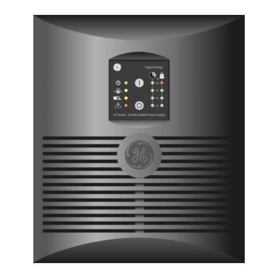
Page 12: Operation
Critical Power OPERATION OPERATING PANEL Fig. 4.1: Operating panel switch / LED main function ‘on’ switch switches on the UPS, starts quick battery test (see 4.6) ‘off’ switch switches off the UPS LED ‘operation’ on when the UPS is operating blinks if the UPS is in standby mode LED ‘on bypass’... -
Page 13: Start-Up
Critical Power START-UP 4.2.1 Start-up, mains available Via front panel: press keypad 'I' (1, fig. 4.1) briefly; LED ‘operation’ (already slowly blinking) will at first blink faster and after a few seconds it will illuminate continuously, indicating that the unit has started up. Via UPS monitoring software: startup after delay, see 4.4.12 for more information. -
Page 14: Use: Status And Alarm Indications
Critical Power USE: STATUS AND ALARM INDICATIONS status indications the operating mode low priority alarms abnormal operating situations high priority alarms situations in which the actual output voltage of the UPS is no longer guaranteed; immediate action should be taken Indicators on front panel (fig. -
Page 15: Standby
Critical Power 4.4.1 Standby The UPS output is off, but the batteries are charging, see 3.6.2 step 5 4.4.2 Normal operation See 4.3.1. 4.4.3 eBoost operation As long as the mains is suitable for the load, the UPS is able to operate in a “green”, high efficiency operating mode: the UPS supplies the load from bypass, while keeping ready for operation in double conversion. -
Page 16: Overload
Critical Power 4.4.8 Overload The demanded power exceeds the normal capacity of the UPS. The alarm occurs when the load is > 100%. If the load exceeds 150% the UPS will immediately switch to bypass, assuming that the conditions for a transfer to bypass are fulfilled. If an overload condition between 110-150% persists, the UPS will also switch to bypass operation. -
Page 17: Use: Setup Mode
Critical Power USE: SETUP MODE The setup mode can only be entered if the UPS is in ‘standby’ -mode: connected to a live wall outlet and switched off (LED 'operation' blinks). Press keypad 'O' and keep it pressed while pressing 'I' simultaneously. Release both buttons. The setup sequence starts with the setup of the output voltage, indicated by a blinking LED ‘operation’. -
Page 18: Battery Management
Critical Power BATTERY MANAGEMENT Maximum battery life and reliability are obtained by the following features: Quick battery test The quick battery test checks whether the batteries and their wiring are healthy. If a quick battery test shows that the batteries are close to being worn out, a 'bad battery' alarm will be generated (see 4.4.9). -
Page 19: Communication
UPS is switched off. For more information please refer to the user manual that comes with the interface software. We strongly recommend to use only original GE software products in combination with the interface port. NOTE The change of some settings can cause the unit to switch from bypass to standby and output power is lost. -
Page 20: Maintenance
USB output). For your safety, only authorized service personnel may remove the cabinet cover. Refer to section 1.3 for further details. GENERAL The GE VH Series UPS is virtually maintenance free: take care of proper environmental conditions and keep air inlets/outlets free of dust. Please read 3.2. NOTE Leave maintenance and service work to qualified and skilled personnel only. -
Page 21: Troubleshooting
Critical Power TROUBLESHOOTING Whenever a malfunction occurs, first check external factors (e.g. connections, temperature, humidity or load) to determine whether the problem is caused by the unit itself or by its environment. Subsequently check the thermal circuit breaker: it may be tripped. If so: reset it (see fig. 3.3) and be sure that the UPS is not overloaded. The following chart is a simple troubleshooting checklist only. -
Page 22: Specifications
Critical Power SPECIFICATIONS VH Series 2000 3000 Ratings Voltage Amperes (VA) with computer type load 2000 3000 Watts (W) with resistive load 1800 2700 Input thermal circuit breaker (A) Internal input fuse 250V, slow (A) Input converter AC input voltage 120-280V Input current waveform sinusoidal, EN 61000-3-2 (IEC 555-2) compliant...