
Related Manuals for Yamaha CRYPTON T110C


Summary of Contents for Yamaha CRYPTON T110C
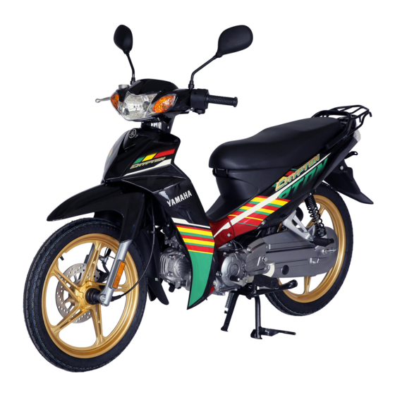
- Page 1 Read this manual carefully before operating this vehicle. OWNER’S MANUAL T110C 40B-F8199-E2...
- Page 2 EAU46090 Read this manual carefully before operating this vehicle. This manual should stay with this vehicle if it is sold.
- Page 3 EAU10102 Welcome to the Yamaha world of motorcycling! As the owner of the T110C, you are benefiting from Yamaha’s vast experience and newest technology regarding the design and manufacture of high-quality products, which have earned Yamaha a reputation for dependability.
-
Page 4: Important Manual Information
IMPORTANT MANUAL INFORMATION EAU10133 Particularly important information is distinguished in this manual by the following notations: This is the safety alert symbol. It is used to alert you to potential personal injury hazards. Obey all safety messages that follow this symbol to avoid possible injury or death. - Page 5 IMPORTANT MANUAL INFORMATION EAU37230 T110C OWNER’S MANUAL ©2012 by Yamaha Motor Co., Ltd. 1st edition, September 2012 All rights reserved. Any reprinting or unauthorized use without the written permission of Yamaha Motor Co., Ltd. is expressly prohibited. Printed in China.
-
Page 6: Table Of Contents
TABLE OF CONTENTS SAFETY INFORMATION ....1-1 FOR YOUR SAFETY – Valve clearance ......6-13 PRE-OPERATION CHECKS ..... 4-1 Tires ..........6-14 DESCRIPTION ........2-1 Cast wheels ......... 6-16 Left view ..........2-1 OPERATION AND IMPORTANT Checking the brake lever free Right view ........2-2 RIDING POINTS......... - Page 7 TABLE OF CONTENTS Checking the steering ....6-26 Checking the wheel bearings ..6-26 Battery ..........6-26 Replacing the fuse ......6-28 Replacing the headlight bulb ..6-28 Replacing the tail/brake light bulb ...........6-29 Replacing a front turn signal light bulb ...........6-30 Replacing a rear turn signal light bulb ...........6-31 Replacing the license plate light bulb ...........6-31...
-
Page 8: Safety Information
SAFETY INFORMATION ● EAU1028A Never operate a motorcycle with- yourself conspicuous appears to out proper training or instruction. be very effective in reducing the Take a training course. Beginners chance of this type of accident. Be a Responsible Owner should receive training from a cer- Therefore: As the vehicle’s owner, you are respon- tified instructor. - Page 9 SAFETY INFORMATION ● Many accidents involve inexperi- • Always signal before turning or Protective Apparel enced operators. In fact, many op- changing lanes. Make sure that The majority of fatalities from motorcy- erators who have been involved in other motorists can see you. cle accidents are the result of head in- accidents do not even have a cur- ●...
- Page 10 SAFETY INFORMATION ● Avoid Carbon Monoxide Poisoning Do not run engine outdoors where When loading within this weight limit, All engine exhaust contains carbon engine exhaust can be drawn into keep the following in mind: monoxide, a deadly gas. Breathing car- a building through openings such ●...
- Page 11 Yamaha accessories, which are avail- formed to your vehicle that change any lightweight as possible and able only from a Yamaha dealer, have of the vehicle’s design or operation should be kept to a minimum. been designed, tested, and approved characteristics can put you and others •...
- Page 12 SAFETY INFORMATION ● tor and may limit control ability, Check that the fuel cock (if therefore, such accessories are equipped) is in the “OFF” position not recommended. and that there are no fuel leaks. ● Use caution when adding electri- ●...
-
Page 13: Description
DESCRIPTION EAU10410 Left view 1. Battery (page 6-26) 2. Fuse (page 6-28) 3. Storage compartment (page 3-9) 4. Owner’s tool kit (page 6-2) 5. Fuel tank cap (page 3-5) 6. Seat lock (page 3-8) 7. Engine oil drain bolt (page 6-9) 8. -
Page 14: Right View
DESCRIPTION EAU10420 Right view 1. Carrier (page 3-10) 2. Helmet holder (page 3-8) 3. Kickstarter (page 3-8) 4. Front brake fluid reservoir (page 6-19) 5. Air filter element (page 6-11) 6. Brake pedal (page 3-5) 7. Engine oil filler cap (page 6-9) -
Page 15: Controls And Instruments
DESCRIPTION EAU10430 Controls and instruments 1. Left handlebar switches (page 3-3) 2. Speedometer unit (page 3-3) 3. Fuel gauge (page 3-3) 4. Main switch/steering lock (page 3-1) 5. Right handlebar switch (page 3-3) 6. Brake lever (page 3-4) 7. Throttle grip (page 6-13) -
Page 16: Instrument And Control Functions
INSTRUMENT AND CONTROL FUNCTIONS EAU10461 EAU47791 To lock the steering Main switch/steering lock (off) All electrical systems are off. The key can be removed. EWA15350 WARNING Never turn the key to “ ” or “ ” while the vehicle is moving. Other- wise the electrical systems will be switched off, which may result in loss of control or an accident. -
Page 17: Indicator Lights
INSTRUMENT AND CONTROL FUNCTIONS To unlock the steering EAU10981 EAU37611 Indicator lights Gear position indicator lights “1” “2” “3”, and “4” The respective indicator light comes on when the transmission is in the 1st, 2nd, 3rd or 4th gear position. EAU11080 High beam indicator light “... -
Page 18: Speedometer Unit
INSTRUMENT AND CONTROL FUNCTIONS EAUT1821 EAU47830 EAU1234B Speedometer unit Fuel gauge Handlebar switches Left 1. Speedometer 1. Fuel gauge 2. Odometer 2. Red zone 1. Dimmer switch “ ” 2. Turn signal switch “ ” The speedometer unit is equipped with The fuel gauge indicates the amount of 3. -
Page 19: Shift Pedal
INSTRUMENT AND CONTROL FUNCTIONS EAU12400 EAU37461 EAU12891 Shift pedal Brake lever Dimmer switch “ ” Set this switch to “ ” for the high beam and to “ ” for the low beam. EAU12460 Turn signal switch “ ” To signal a right-hand turn, push this switch to “... -
Page 20: Brake Pedal
INSTRUMENT AND CONTROL FUNCTIONS EAU12941 EAU37471 EWA11091 Brake pedal Fuel tank cap WARNING Make sure that the fuel tank cap is properly closed after filling fuel. Leaking fuel is a fire hazard. 1. Brake pedal 1. Fuel tank cap 2. “ ”... -
Page 21: Fuel
2. Do not overfill the fuel tank. Stop Your Yamaha engine has been de- EWA15151 filling when the fuel reaches the signed to use unleaded gasoline with a WARNING bottom of the filler tube. -
Page 22: Catalytic Converters
INSTRUMENT AND CONTROL FUNCTIONS EAU13445 ECA10701 EAU13590 Catalytic converters Starter (choke) lever “ ” NOTICE This vehicle is equipped with catalytic Use only unleaded gasoline. The use converters in the exhaust system. of leaded gasoline will cause unre- EWA10862 pairable damage to the catalytic WARNING converter. -
Page 23: Kickstarter
INSTRUMENT AND CONTROL FUNCTIONS EAU47860 EAU13891 EAU37481 Kickstarter Seat Helmet holders To open the seat 1. Insert the key in the lock, and then turn it as shown. 2. Fold the seat up. 1. Kickstarter 1. Helmet holder If the engine fails to start by pushing the The helmet holders are located under start switch, try to start it by using the the seat. -
Page 24: Storage Compartment
INSTRUMENT AND CONTROL FUNCTIONS ● To release a helmet from a helmet EAU14453 Do not exceed the maximum Storage compartment holder load of 167 kg (368 lb) for the ve- Open the seat, remove the helmet from hicle. the helmet holder, and then close the seat. -
Page 25: Carrier
INSTRUMENT AND CONTROL FUNCTIONS EAU15112 EAU55180 Carrier Sidestand (for sidestand- EWA10171 equipped models) WARNING The sidestand is located on the left side ● Do not exceed the load limit of of the frame. Raise the sidestand or 3.0 kg (6.6 lb) for the carrier. lower it with your foot while holding the ●... -
Page 26: For Your Safety - Pre-Operation Checks
6-17, 6-18 • Adjust if necessary. • Make sure that operation is smooth. • Check throttle grip free play. Throttle grip 6-13, 6-23 • If necessary, have Yamaha dealer adjust throttle grip free play and lubricate cable and grip housing. - Page 27 FOR YOUR SAFETY – PRE-OPERATION CHECKS ITEM CHECKS PAGE • Make sure that operation is smooth. Control cables 6-23 • Lubricate if necessary. • Check chain slack. • Adjust if necessary. Drive chain 6-20, 6-22 • Check chain condition. • Lubricate if necessary. •...
-
Page 28: Operation And Important Riding Points
EWA10271 light should come on. If not, ask a 6. After starting the engine, move the WARNING Yamaha dealer to check the elec- starter (choke) back halfway. Failure to familiarize yourself with trical circuit. 7. When the engine is warm, turn the the controls can lead to loss of con- 3. -
Page 29: Starting A Warm Engine
OPERATION AND IMPORTANT RIDING POINTS ● EAU16640 EAU47840 Make sure the neutral indicator Starting a warm engine Shifting light comes on when the trans- Follow the same procedure as for start- mission is in the neutral posi- ing a cold engine with the exception tion. -
Page 30: Tips For Reducing Fuel Consumption
(e.g., in traffic jams, at traffic If any engine trouble should occur lights or at railroad crossings). during the engine break-in period, EAU16863 immediately have a Yamaha dealer check the vehicle. 0–150 km (0–90 mi) Avoid prolonged operation above 1/3 throttle. -
Page 31: Parking
OPERATION AND IMPORTANT RIDING POINTS EAU17213 Parking When parking, stop the engine, and then remove the key from the main switch. EWA10311 WARNING ● Since the engine and exhaust system can become very hot, park in a place where pedestri- ans or children are not likely to touch them and be burned. -
Page 32: Periodic Maintenance And Adjustment
– possibly leading to pending on the weather, terrain, geo- that is certified (if applicable). Yamaha death. See page 1-3 for more in- graphical location, and individual use, dealers are trained and equipped to... -
Page 33: Owner's Tool Kit
If you do not have the tools or experi- ence required for a particular job, have a Yamaha dealer perform it for you. -
Page 34: Periodic Maintenance Chart For The Emission Control System
● From 30000 km (17500 mi), repeat the maintenance intervals starting from 6000 km (3500 mi). ● Items marked with an asterisk should be performed by a Yamaha dealer as they require special tools, data and technical skills. EAU46920 Periodic maintenance chart for the emission control system... -
Page 35: General Maintenance And Lubrication Chart
PERIODIC MAINTENANCE AND ADJUSTMENT EAU17718 General maintenance and lubrication chart ODOMETER READING ANNUAL ITEM CHECK OR MAINTENANCE JOB 1000 km 6000 km 12000 km 18000 km 24000 km CHECK (600 mi) (3500 mi) (7000 mi) (10500 mi) (14000 mi) √ √... - Page 36 PERIODIC MAINTENANCE AND ADJUSTMENT ODOMETER READING ANNUAL ITEM CHECK OR MAINTENANCE JOB 1000 km 6000 km 12000 km 18000 km 24000 km CHECK (600 mi) (3500 mi) (7000 mi) (10500 mi) (14000 mi) • Check operation and for exces- √ √...
- Page 37 PERIODIC MAINTENANCE AND ADJUSTMENT ODOMETER READING ANNUAL ITEM CHECK OR MAINTENANCE JOB 1000 km 6000 km 12000 km 18000 km 24000 km CHECK (600 mi) (3500 mi) (7000 mi) (10500 mi) (14000 mi) • Change. (See page 6-9.) √ Engine oil •...
-
Page 38: Removing And Installing The Cowling And Panel
PERIODIC MAINTENANCE AND ADJUSTMENT EAU18741 Removing and installing the cowling and panel The cowling and panel shown need to be removed to perform some of the maintenance jobs described in this chapter. Refer to this section each time the cowling or panel needs to be re- moved and installed. -
Page 39: Checking The Spark Plug
If the spark plug shows a distinctly dif- ferent color, the engine could be oper- ating improperly. Do not attempt to diagnose such problems yourself. In- stead, have a Yamaha dealer check 1. Spark plug cap the vehicle. 2. Remove the spark plug as shown, with the spark plug wrench includ- ed in the owner’s tool kit. -
Page 40: Engine Oil
PERIODIC MAINTENANCE AND ADJUSTMENT 2. Check the spark plug for electrode To install the spark plug EAU47692 Engine oil erosion and excessive carbon or 1. Clean the surface of the spark plug The engine oil level should be checked other deposits, and replace it if gasket and its mating surface, and before each ride. - Page 41 PERIODIC MAINTENANCE AND ADJUSTMENT To change the engine oil Tightening torque: 1. Start the engine, warm it up for Engine oil drain bolt: several minutes, and then turn it 20 Nm (2.0 m·kgf, 14 ft·lbf) off. 5. Refill with the specified amount of 2.
-
Page 42: Cleaning The Air Filter Element
PERIODIC MAINTENANCE AND ADJUSTMENT addition, do not use oils labeled EAU47771 Cleaning the air filter element “ENERGY CONSERVING II” or The air filter element should be cleaned higher. or replaced at the intervals specified in ● Make sure that no foreign mate- the periodic maintenance and lubrica- rial enters the crankcase. -
Page 43: Adjusting The Carburetor
The engine should never be op- buretor adjustments should be left to a follows at the intervals specified in the erated without the air filter ele- Yamaha dealer, who has the neces- periodic maintenance and lubrication ment installed, otherwise the sary professional knowledge and expe- chart. -
Page 44: Checking The Throttle Grip Free Play
The valve clearance changes with use, resulting in improper air-fuel mixture and/or engine noise. To prevent this from occurring, the valve clearance must be adjusted by a Yamaha dealer at the intervals specified in the periodic maintenance and lubrication chart. 1. Throttle stop screw Engine idling speed: 1400–1600 r/min... -
Page 45: Tires
Operation of this vehicle with im- proper tire pressure may cause se- sidewall is cracked, have a Yamaha EWA10511 vere injury or death from loss of dealer replace the tire immediately. - Page 46 After extensive tests, only the tires list- and brake-related parts, includ- ed below have been approved for this ing the tires, should be left to a model by Yamaha Motor Co., Ltd. Yamaha dealer, who has the necessary professional knowl- edge and experience.
-
Page 47: Cast Wheels
There should be no free play at the er damage before each ride. If any brake lever end. If there is free play, damage is found, have a Yamaha have a Yamaha dealer inspect the dealer replace the wheel. Do not brake system. -
Page 48: Adjusting The Brake Pedal Free Play
Adjusting the brake pedal free Checking the shift pedal play The operation of the shift pedal should be checked before each ride. If opera- tion is not smooth, have a Yamaha dealer check the vehicle. 1. Brake pedal free play adjusting nut EWA10680 WARNING 1. -
Page 49: Brake Light Switches
1. Brake pad wear indicator groove by a Yamaha dealer. Each front brake pad is provided with 1. Remove panel A. (See page 6-7.) wear indicator grooves, which allow 2. -
Page 50: Checking The Brake Fluid Level
Observe NOTICE point that the wear indicator reaches these precautions: the wear limit line, have a Yamaha Brake fluid may damage painted sur- dealer replace the brake shoes as a faces or plastic parts. Always clean set. -
Page 51: Changing The Brake Fluid
Changing the brake fluid Drive chain slack the brake fluid level to gradually go Have a Yamaha dealer change the The drive chain slack should be down. A low brake fluid level may indi- brake fluid at the intervals specified in... - Page 52 EAU55190 To adjust the drive chain slack both drive chain pullers are in the same Consult a Yamaha dealer before ad- position for proper wheel alignment. justing the drive chain slack. 1. Place the motorcycle on the cen- terstand.
-
Page 53: Cleaning And Lubricating The Drive
Tightening torques: Locknut: For a thorough cleaning, have a 7 Nm (0.7 m·kgf, 5.1 ft·lbf) Yamaha dealer remove the drive chain Axle nut: and soak it in solvent. 60 Nm (6.0 m·kgf, 43 ft·lbf) Brake torque rod nut: 2. -
Page 54: Checking And Lubricating The Cables
Yamaha dealer at the intervals speci- ed if necessary. If a cable is damaged fied in the periodic maintenance chart. -
Page 55: Checking And Lubricating The Brake Pedal
Recommended lubricant: Lithium-soap-based grease metal contact surfaces should be lubri- cated if necessary. EWA10741 WARNING If the centerstand or sidestand does not move up and down smoothly, have a Yamaha dealer check or re- pair it. Otherwise, the centerstand or 6-24... -
Page 56: Lubricating The Swingarm Pivots
The swingarm pivots must be lubricat- intervals specified in the periodic main- ed by a Yamaha dealer at the intervals tenance and lubrication chart. specified in the periodic maintenance and lubrication chart. -
Page 57: Checking The Steering
If any free burns. Avoid any contact with hub or if the wheel does not turn play can be felt, have a Yamaha skin, eyes or clothing and al- smoothly, have a Yamaha dealer check dealer check or repair the steering. - Page 58 To charge the battery necting the positive lead. [ECA17710] Have a Yamaha dealer charge the bat- 2. If the battery will be stored for more tery as soon as possible if it seems to than two months, check it at least have discharged.
-
Page 59: Replacing The Fuse
6. If the fuse immediately blows 2. Screw lens. again, have a Yamaha dealer 4. Remove the blown fuse, and then Do not use a headlight bulb of a check the electrical system. install a new fuse of the specified wattage higher than specified. -
Page 60: Replacing The Tail/Brake Light Bulb
7. Install the headlight bulb cover. 8. Install the cowling. 9. Have a Yamaha dealer adjust the 1. Headlight bulb cover headlight beam if necessary. 3. Remove the headlight bulb holder (together with the bulb) by turning it counterclockwise. -
Page 61: Replacing A Front Turn Signal Light Bulb
PERIODIC MAINTENANCE AND ADJUSTMENT 3. Remove the burnt-out bulb by EAU47741 Replacing a front turn signal pushing it in and turning it counter- light bulb clockwise. 1. Remove cowling A. (See page 6-7.) 2. Remove the turn signal light bulb socket (together with the bulb) by turning it counterclockwise. -
Page 62: Replacing A Rear Turn Signal Light Bulb
PERIODIC MAINTENANCE AND ADJUSTMENT EAUS1611 EAU47910 Replacing a rear turn signal Replacing the license plate light bulb light bulb 1. Remove the turn signal light lens 1. Remove the license plate light cov- by removing the screw. er by removing the screw. 1. -
Page 63: Bulb
PERIODIC MAINTENANCE AND ADJUSTMENT 3. Insert a new bulb into the socket. EAUW0343 Replacing an auxiliary light 4. Install the license plate light cover bulb by installing the screw. This model is equipped with two auxil- iary lights. If an auxiliary light bulb burns out, replace it as follows. -
Page 64: Front Wheel
PERIODIC MAINTENANCE AND ADJUSTMENT EAU24360 gether with the brake disc, oth- Front wheel erwise the brake pads will be forced shut. [ECA11071] EAU55220 To remove the front wheel EWA10821 WARNING To avoid injury, securely support the vehicle so there is no danger of it falling over. - Page 65 PERIODIC MAINTENANCE AND ADJUSTMENT 6. While applying the front brake, push down hard on the handlebars several times to check if the front fork compresses and rebounds smoothly. 7. Place the motorcycle on the cen- terstand. 8. Install the rubber cap. 9.
-
Page 66: Rear Wheel
PERIODIC MAINTENANCE AND ADJUSTMENT EAU25080 5. Disconnect the brake torque rod Rear wheel from the brake shoe plate by re- moving the cotter pin, the nut, the EAU55240 washer and the bolt. To remove the rear wheel EWA10821 WARNING To avoid injury, securely support the vehicle so there is no danger of it falling over. - Page 67 PERIODIC MAINTENANCE AND ADJUSTMENT 8. Push the wheel forward, and then remove the drive chain from the When tightening the axle nut, hold the rear sprocket. wheel axle with a wrench to keep it from turning. The drive chain does not need to be disassembled in order to remove and Tightening torques: Brake torque rod nut:...
-
Page 68: Troubleshooting
However, should your motorcycle require any repair, take it to a Yamaha dealer, whose skilled technicians have the necessary tools, experience, and know-how to service the motorcycle properly. -
Page 69: Troubleshooting Chart
Remove the spark plug and check the electrodes. The engine does not start. Have a Yamaha dealer check the vehicle. Check the compression. 4. Compression The engine does not start. There is compression. -
Page 70: Motorcycle Care And Storage
Some models are equipped with ble. Rust and corrosion can develop matte colored finished parts. Be Cleaning sure to consult a Yamaha dealer for even if high-quality components are ECA10772 advice on what products to use be- used. A rusty exhaust pipe may go un-... - Page 71 MOTORCYCLE CARE AND STORAGE off any detergent residue using Test the product on a small hid- plenty of water, as it is harmful den part of the windshield to Salt sprayed on roads in the winter may to plastic parts. make sure that it does not leave remain well into spring.
-
Page 72: Storage
WARNING ing it with a tarp, while it is still ● Contaminants on the brakes or tires Consult a Yamaha dealer for ad- wet, will allow water and humid- can cause loss of control. vice on what products to use. - Page 73 MOTORCYCLE CARE AND STORAGE 2. For motorcycles equipped with a WARNING! To prevent dam- cessively cold or warm place [less fuel cock that has an “OFF” posi- age or injury from sparking, than 0 °C (30 °F) or more than 30 tion: Turn the fuel cock lever to make sure to ground the °C (90 °F)].
-
Page 74: Specifications
SPECIFICATIONS Dimensions: Engine oil: Carburetor: Type × quantity: Overall length: Recommended brand: 1870 mm (73.6 in) YAMALUBE MP17 x 1 Overall width: Type: Spark plug(s): 675 mm (26.6 in) SAE 10W-30, 10W-40, 10W-50, 15W-40, Manufacturer/model: Overall height: 20W-40 or 20W-50 NGK/CR6HSA 1040 mm (40.9 in) Spark plug gap:... - Page 75 SPECIFICATIONS Chassis: Front: Front suspension: 200 kPa (2.00 kgf/cm², 29 psi) Frame type: Type: Rear: Backbone Telescopic fork 225 kPa (2.25 kgf/cm², 33 psi) Caster angle: Spring/shock absorber type: Loading condition: 27.00 ° Coil spring/oil damper 90–167 kg (198–368 lb) Trail: Wheel travel: Front:...
- Page 76 SPECIFICATIONS Rear turn signal light: 12 V, 10.0 W × 2 Auxiliary light: 12 V, 3.0 W × 2 License plate light: 12 V, 5.0 W × 1 Meter lighting: 12 V, 1.7 W × 1 Neutral indicator light: 12 V, 1.7 W × 1 Gear position indicator light: 12 V, 3.0 W ×...
-
Page 77: Consumer Information
Engine serial number Record the frame serial number and engine serial number in the spaces pro- vided below for assistance when order- ing spare parts from a Yamaha dealer or for reference in case the vehicle is stolen. FRAME SERIAL NUMBER: 1. - Page 78 INDEX Engine oil..........6-9 Engine serial number......9-1 Air filter element, cleaning..... 6-11 Parking ............5-4 Engine, starting a warm......5-2 Auxiliary light bulb, replacing ....6-32 Part locations .......... 2-1 Frame serial number ......9-1 Battery........... 6-26 Safety information ........1-1 Front fork, checking ......
- Page 79 INDEX Turn signal light bulb (rear), replacing..........6-31 Turn signal switch........3-4 Valve clearance ........6-13 Wheel bearings, checking ....6-26 Wheel (front) ......... 6-33 Wheel (rear).......... 6-35 Wheels..........6-16...
- Page 82 PRINTED IN CHINA 2012.10-0.3×1 CR...