Table of Contents
Table of Contents

Related Manuals for Lenovo RackSwitch G7052


Summary of Contents for Lenovo RackSwitch G7052
-
Page 1: Installation Guide
Lenovo RackSwitch G7052 Installation Guide... - Page 2 LIMITED AND RESTRICTED RIGHTS NOTICE: If data or software is delivered pursuant a General Services Administration “GSA” contract, use, reproduction, or disclosure is subject to restrictions set forth in Contract No. GS-35F-05925. Lenovo and the Lenovo logo are trademarks of Lenovo in the United States, other countries, or both.
-
Page 3: Table Of Contents
Other Important Safety Notices ....13 Chapter 1. The RackSwitch G7052 ....15 Introduction . - Page 4 Removing the G7052 from a Lenovo System x or Power Rack..59 Removing the G7052 from a Lenovo iDataPlex Rack ..62 Removing the Air-Duct Option ....65 Replacing the G7052 .
- Page 5 Power Specifications ..... . . 86 Switching Performance ..... . 86 © Copyright Lenovo 2015 Contents...
- Page 6 G7052 Installation Guide...
-
Page 7: Safety Information
Prima di installare questo prodotto, leggere le Informazioni sulla Sicurezza. Πред да инсталира овој продукт, прочитајте информацијата за безбедност. Les sikkerhetsinformasjonen (Safety Information) før du installerer dette produktet. Przed zainstalowaniem tego produktu, należy zapoznać się z książką “Informacje dotyczace bezpieczeństwa” (Safety Information). © Copyright Lenovo 2015 Safety Information... - Page 8 Antes de instalar este produto, leia as Informações sobre Segurança. Перед установкой продукта прочтитe инcтрyкции по тexникe безопасности. Pred inštaláciou tohto zariadenia si prečítajte Bezpečnostné predpisy. Pred namestitvijo tega proizvoda preberite Varnostne informacije. Antes de instalar este producto, lea la información de seguridad. Läs säkerhetsinformationen innan du installerar den här produkten.
-
Page 9: Safety Statements
Laser radiation when open. Do not stare into the beam, do not view directly with optical instruments, and avoid direct exposure to the beam. Class 1 Laser Product Laser Klasse 1 Laser Klass 1 Luokan 1 Laserlaite Appareil À Laser de Classe 1 © Copyright Lenovo 2015 Safety Information... - Page 10 Statement 5 CAUTION: The power control button on the device and the power switch on the power supply do not turn off the electrical current supplied to the device. The device also might have more than one power cord. To remove all electrical current from the device, ensure that all power cords are disconnected from the power source.
- Page 11 Statement 25 CAUTION: This product contains a Class 1M laser. Do not view directly with optical instruments. Statement 26 CAUTION: Do not place any object on top of rack-mounted devices. © Copyright Lenovo 2015 Safety Information...
- Page 12 Statement 31 DANGER Electrical current from power, telephone, and communication cables is hazardous. To avoid a shock hazard: • Do not connect or disconnect any cables or perform installation, maintenance, or reconfiguration of this product during an electrical storm. • Connect all power cords to a properly wired and grounded power source.
-
Page 13: Other Important Safety Notices
Multiple devices extended into the service position can cause your rack cabinet to tip. • If you are not using the Lenovo 9308 rack cabinet, securely anchor the rack cabinet to ensure its stability. Other Important Safety Notices Important This product is also designed for IT power distribution systems with phase-to-phase voltage of 230V. - Page 14 G7052 Installation Guide...
-
Page 15: Chapter 1. The Rackswitch G7052
The console output described or referenced in this document might differ slightly from that displayed by your system. Output varies according to the type of Lenovo chassis and the firmware versions and options that are installed. Notices and Statements in this Document The caution and danger statements in this document are also in the multilingual Safety Information document, which is on the included Documentation CD. -
Page 16: The Documentation Cd
• Note: These notices provide important tips, guidance, or advice. • Important: These notices provide information or advice that might help you avoid inconvenient or problem situations. • Attention: These notices indicate potential damage to programs, devices, or data. An attention notice is placed just before the instruction or situation in which damage could occur. -
Page 17: Related Documentation
Related Documentation Additional or updated product documents may be available from the Lenovo website. Such documents may cover features not described in the original documentation that comes with the switch, or may include technical updates or corrections. You can obtain up-to-date information on the Lenovo support website: http://support.lenovo.com/... - Page 18 G7052 Installation Guide...
-
Page 19: Chapter 2. Switch Components
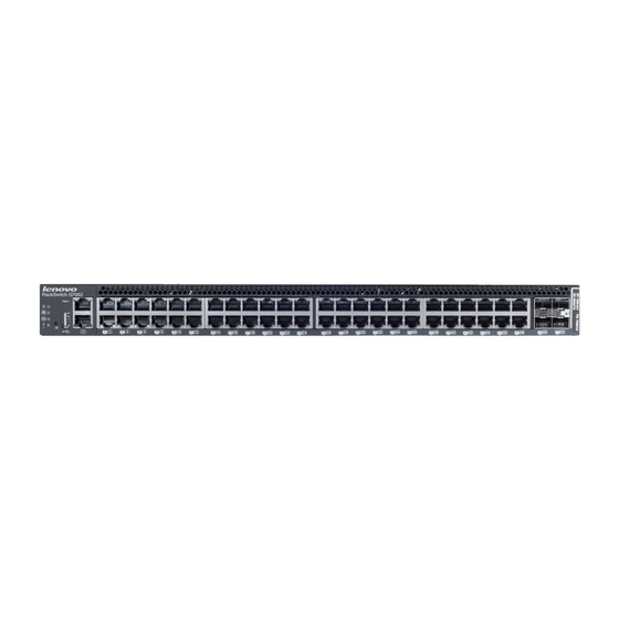
The following illustrations show the features on the front and rear of the switch. Figure 1. RackSwitch G7052 front panel Management Panel RJ-45 ports SFP+ ports Figure 2. RackSwitch G7052 management panel detail RJ-45 Management Port Status RJ-45 LEDs... -
Page 20: Management Panel
Management Panel RJ-45 Serial Console Port The RJ-45 port on the front management panel is available for switch console management. The port operates using RS-232 serial communications. A compatible console cable kit is included with the switch. To connect a computer or terminal to the switch using the included kit, first connect one end of the Category 5 patch cable to the RJ-45 serial port on the G7052, then connect the other end of the patch cable to the RJ-45-to-DB9 adapter (see the following illustration). -
Page 21: Rj-45 Management Port
Normal reset—Press and release Reset. The switch resets and reloads the configuration files. • Factory reset—Press and hold Reset for more than five seconds. The switch resets and reverts all configuration settings to the factory defaults. © Copyright Lenovo 2015 Chapter 2: Switch Components... -
Page 22: System Status Leds
System Status LEDs The following table describes the behavior of the system status LEDs: Table 3. System status LEDs behavior State Functional Meaning Total power failure. - Service Steady blue An operational command has been sent to light the LED so that this device can be more readily located. Flashing blue Service is required due to failure of the general system, its cooling fans, stacking function... -
Page 23: Sfp+ Ports
Appareil À Laser de Classe 1 Four 10 GbE SFP+ ports are available on the front panel. These ports accept supported optical or copper SFP or SFP+ transceivers, or DACs. Transceivers must be purchased separately. © Copyright Lenovo 2015 Chapter 2: Switch Components... -
Page 24: Rj-45 Ports
SFP+ LEDs Status LEDs for the SFP+ ports are described in the following table. Table 4. SFP+ port status LED behavior State Functional Meaning Link/Activity Steady green Link up No link Flashing green Activity RJ-45 Ports There are forty-eight 10/100/1000BASE-T Gigabit Ethernet (GbE) RJ-45 ports on the front of the G7052. -
Page 25: Rear Panel
The device also might have more than one power cord. To remove all electrical current from the device, ensure that all power cords are disconnected from the power source. © Copyright Lenovo 2015 Chapter 2: Switch Components... - Page 26 Statement 31 DANGER Electrical current from power, telephone, and communication cables is hazardous. To avoid a shock hazard: • Do not connect or disconnect any cables or perform installation, maintenance, or reconfiguration of this product during an electrical storm. • Connect all power cords to a properly wired and grounded power source.
- Page 27 The LED flashes when only one power cord is connected, and is steady when both power cords are connected (see “System Status LEDs” on page 22). © Copyright Lenovo 2015 Chapter 2: Switch Components...
- Page 28 G7052 Installation Guide...
-
Page 29: Chapter 3. Installing G7052 Hardware And Options
– “Installing the G7052 in a Standard Equipment Rack” on page 35 – “Installing the G7052 in a Lenovo System x or Power Rack” on page 38 – “Installing the G7052 in a Lenovo iDataPlex Rack” on page 43 •... -
Page 30: Before Installing The G7052
Print this page and record product information below. Keep the information in a safe place for future reference. You will need this information when you register the switch or open a service call with Lenovo. Table 6. Important product information... -
Page 31: Required Tools
Electrostatic discharge wrist strap Package Contents The basic G7052 package contains the following items: • One RackSwitch G7052 unit with rear-to-front airflow • One two-post mounting kit for standard 19” equipment racks: – Two mounting brackets – Screws to attach brackets to the switch unit –... -
Page 32: Preventing Electric Shock
Preventing Electric Shock This product does not contain any user-serviceable parts. Do not remove the cover of this device. The G7052 AC power module is designed to work with single-phase power systems that have a grounded neutral conductor. For your safety, a power cord with a ground attachment plug is available to order for use with this product. - Page 33 2. Remove the signal cables from the devices. connectors. 5. Connect power cords to their 3. Remove all cables from the sources. devices. 6. Turn ON all the power sources. © Copyright Lenovo 2015 Chapter 3: Installing G7052 Hardware and Options...
-
Page 34: Handling Static-Sensitive Devices
Handling Static-Sensitive Devices Attention: Static electricity can damage the switch and other electronic devices. To avoid damage, keep static-sensitive devices in their static-protective packages until you are ready to install them. To reduce the possibility of electrostatic discharge, observe the following precautions: •... -
Page 35: Installing The G7052 In A Rack
Installation instructions begin on page ® • For a Lenovo System x or Power 4-post rack, use the Lenovo Adjustable 19” 4-Post Rail Kit. This kit must be purchased separately. Installation instructions begin on page ®... - Page 36 To install the G7052 in a standard equipment rack, complete the following steps: 1. Locate, record, and retain the product switch information in order to configure and register your product. See “Recording Important Product Information” on page Note: If this switch is a replacement switch, copy the product information from the original switch onto the RID label that is shipped with replacement switch and affix the new label to the bottom of the new switch.
- Page 37 8. Initialize the switch. See Chapter 5, “Initializing the G7052,” on page 9. If the switch is a replacement unit, set Vital Product Data (see “Configuring Vital Product Data” on page 66). © Copyright Lenovo 2015 Chapter 3: Installing G7052 Hardware and Options...
-
Page 38: Installing The G7052 In A Lenovo System X Or Power Rack
Installing the G7052 in a Lenovo System x or Power Rack ® This section describes how to install the G7052 in a Lenovo System x or Power 4-post rack, using the Lenovo Adjustable 19” 4-Post Rail Kit. This kit must be purchased separately. It includes the following parts: Table 8. - Page 39 (Item 2). Torque the screws to approximately 2.0 newton-meters (Nm) ± 0.1 Nm (17.7 inch-pounds). 4. From the front, slide the switch into the rack at the desired height. © Copyright Lenovo 2015 Chapter 3: Installing G7052 Hardware and Options...
- Page 40 5. Secure the switch to the front rack posts with M6 screws (Item 3), washers (Item 10), and either clip nuts (Item 4) or cage nuts (Item 5). Torque the screws to approximately 5.7 Nm ± 0.1 Nm (50 inch-pounds). 6.
- Page 41 Torque the screws to approximately 0.5 Nm (4 inch-pounds). 9. If installing the 1U air-duct option, see the instruction on page 10. Connect all external cables in accordance with the “Cabling Guidelines” on page © Copyright Lenovo 2015 Chapter 3: Installing G7052 Hardware and Options...
- Page 42 11. If not using the 1U air-duct option, install the power cord retention clip. Note: The power cord retention clip is not used when the 1U air-duct option is installed. 12. Initialize the switch. See Chapter 5, “Initializing the G7052,” on page 13.
-
Page 43: Installing The G7052 In A Lenovo Idataplex Rack
Installing the G7052 in a Lenovo iDataPlex Rack This section describes how to install the G7052 in a Lenovo iDataPlex rack. The iDataPlex mounting kit allows the switch to be mounted either horizontally or vertically. The kit must be purchased separately. It includes the following parts: Table 9. - Page 44 2. Remove the rear cover screws: 3. Attach front mounting brackets (Item 1) and rear mounting brackets (Item 6) to each side of the switch with M4 screws (Item 2). Torque the screws to approximately 2 newton-meters (Nm) +/- 0.1 Nm (17.7 inch-pounds). 4.
- Page 45 5.7 Nm +/- 0.1 Nm (50 inch-pounds). 7. If installing the 1U air-duct option, see the instruction on page 8. Connect all external cables in accordance with the “Cabling Guidelines” on page © Copyright Lenovo 2015 Chapter 3: Installing G7052 Hardware and Options...
- Page 46 9. If not using the 1U air-duct option, install the power cord retention clip. Note: The power cord retention clip is not used when the 1U air-duct option is installed. 10. Initialize the switch. See Chapter 5, “Initializing the G7052,” on page 11.
-
Page 47: Installing The Air-Duct Option
(2-post application). If the switch has an undesirable amount of sag, it is recommended to use a 4-post mounting kit. Attention: For earthquake stability, mount the switch in a 4-post rack. © Copyright Lenovo 2015 Chapter 3: Installing G7052 Hardware and Options... - Page 48 Statement 26 CAUTION: Do not place any object on top of rack-mounted devices. To install the 1U air-duct option in a 19” rack, complete the following steps. 1. Loosen and remove the mounting screws from both sides of the mounting rail and set them aside to reuse for securing the foam carrier in the next step.
- Page 49 M6 screws M3.5 screws 5. Secure the air-duct mounting bracket to the rack chassis with M3.5 screws. Torque the screws to approximately 1.1 Nm ± 0.1 Nm (10 inch-pounds). © Copyright Lenovo 2015 Chapter 3: Installing G7052 Hardware and Options...
- Page 50 6. Gently slide the air-duct unit side flanges into the card guides until the unit is seated firmly. Make sure that the foam strip is oriented on top. Foam Card guides thumbscrews Side flanges 7. Secure the air-duct unit to the air-duct brackets with the two M4 thumbscrews. G7052 Installation Guide...
-
Page 51: Installing Port Transceivers
There are no serviceable parts inside the device. • Use of controls or adjustments or performance of procedures other than those specified herein might result in hazardous radiation exposure. © Copyright Lenovo 2015 Chapter 3: Installing G7052 Hardware and Options... -
Page 52: Installing An Sfp+ Optical Transceiver
DANGER Some laser products contain an embedded Class 3A or Class 3B laser diode. Note the following. Laser radiation when open. Do not stare into the beam, do not view directly with optical instruments, and avoid direct exposure to the beam. Class 1 Laser Product Laser Klasse 1 Laser Klass 1... - Page 53 To remove an SFP+ optical transceiver, disconnect the fiber-optic cable, and pull down the locking lever to release the transceiver. After you remove the transceiver, replace the safety cap. © Copyright Lenovo 2015 Chapter 3: Installing G7052 Hardware and Options...
- Page 54 G7052 Installation Guide...
-
Page 55: Chapter 4. Removing And Replacing G7052 Components
– “Removing the G7052 from a Standard Equipment Rack” on page 57 – “Removing the G7052 from a Lenovo System x or Power Rack” on page 59 – “Removing the G7052 from a Lenovo iDataPlex Rack” on page 62 •... - Page 56 To remove one of the installed SFP or SFP+ transceiver modules from the switch, complete the following steps. 1. Disconnect the port cable from the transceiver. 2. Pull down the locking lever to release the transceiver. 3. Gently slide the transceiver out of the switch. 4.
-
Page 57: Removing The G7052 From A Standard Equipment Rack
1. If the power cord retention clip is installed, remove it: 2. Disconnect all external cables. 3. If the air-duct option has been installed, remove it as described in “Removing the Air-Duct Option” on page © Copyright Lenovo 2015 Chapter 4: Removing and Replacing G7052 Components... - Page 58 4. Loosen and remove M6 screws, washers, and clip nuts (or cage nuts) to release the switch unit from the rack. 5. Slide the switch unit out of the rack. 6. Loosen and remove the M4 screws attaching the mounting bracket on each side of the switch.
-
Page 59: Removing The G7052 From A Lenovo System X Or Power Rack
Removing the G7052 from a Lenovo System x or Power Rack This section describes how to remove the G7052 from a Lenovo System x or Power 4-post rack. To remove the G7052 from a System x or Power rack, complete the following steps: 1. - Page 60 4. Loosen and remove M3.5 screws that secure the rear brackets to the front brackets. 5. Loosen and remove the M6 screws, washers, and clip nuts (or cage nuts) that attach the filler plate and rear mounting brackets to the rear rack posts. 6.
- Page 61 9. Loosen and remove the M4 screws that attach the front mounting brackets to each side of the switch. 10. If replacing the unit with another G7052, see “Replacing the G7052” on page © Copyright Lenovo 2015 Chapter 4: Removing and Replacing G7052 Components...
-
Page 62: Removing The G7052 From A Lenovo Idataplex Rack
Removing the G7052 from a Lenovo iDataPlex Rack This section describes how to remove the G7052 from a Lenovo iDataPlex rack. To remove the G7052 from an iDataPlex rack, complete the following steps: 1. If the power cord retention clip is installed, remove it: 2. - Page 63 4. Loosen and remove the M6 washers, screws, and clip nuts that attach the alignment plate. 5. Loosen and remove the M6 washers and screws that mount the switch into the rack. 6. Slide the switch out of the rack. © Copyright Lenovo 2015 Chapter 4: Removing and Replacing G7052 Components...
- Page 64 7. Loosen and remove the M4 screws that attach front and rear mounting brackets to each side of the switch. 8. If replacing the unit with another G7052, see “Replacing the G7052” on page G7052 Installation Guide...
-
Page 65: Removing The Air-Duct Option
Removing the Air-Duct Option The G7052 supports an optional 1U air duct to maximize air flow conditions in a Lenovo Power Systems Group rack. To remove an installed 1U air-duct option from a 19” rack, complete the following steps. 1. Loosen the M4 thumbscrews securing the air-duct unit to the mounting brackets. -
Page 66: Replacing The G7052
Replacing the G7052 Preparing and Returning the G7052 If replacing the G7052, remove all associated components and options according to the instructions in this chapter. Remove and retain clips, cords, cables, modules, caps or blanks, air-duct option (if installed), and any mounting hardware. These items can then be reinstalled on the replacement unit. - Page 67 System Information at 0:11:46 Wed Jan 6, 2015 Time zone: America/US/Pacific Daylight Savings Time Status: Disabled Lenovo RackSwitch G7052 Switch has been up for 0 days, 0 hours, 10 minutes and 45 seconds. Last boot: 0:11:36 Wed Jan 6, 2015 (reset from console) MAC address: fc:cf:62:9d:2b:00 IP (If 1) address: 192.168.49.50...
- Page 68 G7052 Installation Guide...
-
Page 69: Chapter 5. Initializing The G7052
You can access the switch CLI through the serial console port on the front panel of the switch. This port uses RS-232 serial communications. Use the console cable kit to connect the serial console port to a terminal or a computer running a terminal emulation program. © Copyright Lenovo 2015... -
Page 70: Using The Management Port
Memory Test ........ Production Mode PPCBoot 0.0.0.10 (new flash) Memory Test (0x00) ......PASSED Lenovo RS G7052 Jan 6 00:11:36 2015: Password: At the prompt, type the switch password and press Enter. The default is admin. Note: If the switch has already started prior to your connection, you may need to press Enter to display the password prompt. -
Page 71: Configuring An Ip Interface For Remote Access
In addition, you can configure the switch for management using an SNMP-based network management system or a web-browser. For more information about using the CLI, see the Command Reference guide for your specific switch and firmware version. © Copyright Lenovo 2015 Chapter 5: Initializing the G7052... -
Page 72: Updating Firmware
Updating Firmware If firmware updates are available, you can download them from the Lenovo website. The switch might have features that are not described in the documentation that comes with the switch, and the documentation might be updated occasionally to include information about those features, or technical updates might be available to provide additional information that is not included in the switch documentation. -
Page 73: Chapter 6. Troubleshooting
If you have problems accessing the switch or working with the firmware, see the Command Reference for the switch. For information about calling Lenovo for service, see Appendix A, “Getting Help and Technical Assistance”... - Page 74 G7052 Installation Guide...
-
Page 75: Appendix A. Getting Help And Technical Assistance
If you need help, service, or technical assistance or just want more information about Lenovo products, you will find a wide variety of sources available from Lenovo to assist you. This appendix will help you obtain additional information about Lenovo and Lenovo products, and determine what to do if you experience a problem with your Lenovo system or optional device. - Page 76 G7052 Installation Guide...
-
Page 77: Appendix B. Notices
Web sites. The materials at those Web sites are not part of the materials for this Lenovo product, and use of those Web sites is at your own risk. -
Page 78: Trademarks
(TBW). A device that has exceeded this limit might fail to respond to system-generated commands or might be incapable of being written to. Lenovo is not responsible for replacement of a device that has exceeded its maximum guaranteed number of program/erase cycles, as documented in the Official Published Specifications for the device. -
Page 79: Recycling Information
Lenovo makes no representations or warranties with respect to non-Lenovo products. Support (if any) for the non-Lenovo products is provided by the third party, not Lenovo. Some software might differ from its retail version (if available) and might not include user manuals or all program functionality. -
Page 80: Particulate Contamination
If Lenovo determines that the levels of particulates or gases in your environment have caused damage to the device, Lenovo may condition provision of repair or replacement of devices or parts on implementation of appropriate remedial measures to mitigate such environmental contamination. -
Page 81: Telecommunication Regulatory Statement
Properly shielded and grounded cables and connectors must be used in order to meet FCC emission limits. Lenovo is not responsible for any radio or television interference caused by using other than recommended cables and connectors or by unauthorized changes or modifications to this equipment. -
Page 82: European Union Emc Directive Conformance Statement
EU-Mitgliedsstaaten und hält die Grenzwerte der EN 55022 Klasse A ein. Um dieses sicherzustellen, sind die Geräte wie in den Handbüchern beschrieben zu installieren und zu betreiben. Des Weiteren dürfen auch nur von der Lenovo empfohlene Kabel angeschlossen werden. Lenovo übernimmt keine Verantwortung für die Einhaltung der Schutzanforderungen, wenn das Produkt ohne Zustimmung... -
Page 83: Vcci Class A Statement
Dieses Gerät ist berechtigt, in übereinstimmung mit dem Deutschen EMVG das EG-Konformitätszeichen - CE - zu führen. Verantwortlich für die Konformitätserklärung nach Paragraf 5 des EMVG ist die Lenovo (Deutschland) GmbH, Gropiusplatz 10, D-70563 Stuttgart. Informationen in Hinsicht EMVG Paragraf 4 Abs. (1) 4: Das Gerät erfüllt die Schutzanforderungen nach EN 55024 und EN 55022... -
Page 84: Japan Electronics And Information Technology Industries Association (Jeita) Statement
Japan Electronics and Information Technology Industries Association (JEITA) Statement Japanese Electronics and Information Technology Industries Association (JEITA) Confirmed Harmonics Guideline (products less than or equal to 20 A per phase). Japan Electronics and Information Technology Industries Association (JEITA) Confirmed Harmonics Guidelines with Modifications (products greater than 20 A per phase). -
Page 85: Appendix C. Technical Specifications
10 to 90% operating Relative humidity (non-condensing), 10 to 90% storage Altitude, operating 2,000 m (6,561 ft) Altitude, storage 12,190 m (40,000 ft) Acoustic noise Less than 65dB Heat dissipation 240 BTU/h (typical) 270 BTU/h (maximum) © Copyright Lenovo 2015... -
Page 86: Power Specifications
Power Specifications The power specifications for the G7052 are listed in the following table. Table 13. G7052 AC power specifications Specification Measurement Number of power supplies AC-input frequency (universal) 50–60 Hz AC-input voltage (universal) 100–240 VAC AC inrush current 30 A (RMS) @ 115 VAC/60 Hz 60 A (RMS) @ 230 VAC/50 Hz AC-input current (typical) 0.61 A (RMS) @ 120 VAC/60 Hz...