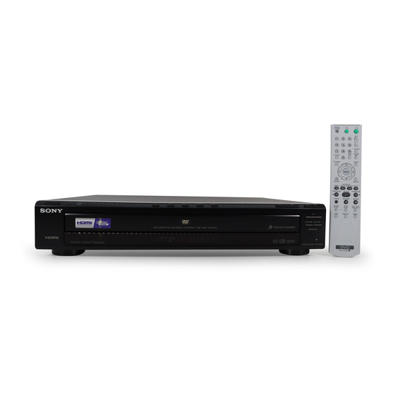
Sony DVP-NC85H Service Manual
Hide thumbs
Also See for DVP-NC85H:
- Specifications (2 pages) ,
- Specifications (2 pages) ,
- Operating instructions manual (80 pages)
Table of Contents
Quick Links
SERVICE MANUAL
System
Laser: Semiconductor laser
Signal format system: NTSC
Audio characteristics
Frequency response: DVD VIDEO
(PCM 96 kHz): 2 Hz to 44 kHz
(±1.0 dB)/DVD VIDEO (PCM 48 kHz):
2 Hz to 22 kHz (±0.5 dB)/CD: 2 Hz to
20 kHz (±0.5 dB)
Signal-to-noise ratio (S/N ratio): 115 dB
(LINE OUT L/R (AUDIO) jacks only)
Harmonic distortion: 0.003%
Dynamic range: DVD VIDEO:
103 dB/CD: 99 dB
Wow and flutter: Less than detected value
(±0.001% W PEAK)
SPECIFICATIONS
Outputs
(Jack name: Jack type/Output level/
Load impedance)
LINE OUT (AUDIO): Phono jack/
2 Vrms/ 10 kilohms
DIGITAL OUT (OPTICAL):
Optical output jack/–18 dBm
(wave length 660 nm)
DIGITAL OUT (COAXIAL): Phono jack/
0.5 Vp-p/75 ohms
HDMI OUT: Type A (19 pin)
COMPONENT VIDEO OUT (Y, P
Phono jack/Y: 1.0 Vp-p/P
, P
B
interface
*1
= 0.648 Vp-p, progressive or
interface
*2
= 0.7 Vp-p/75 ohms
*1
BLACK LEVEL
(COMPONENT OUT) is ON
*2
BLACK LEVEL
(COMPONENT OUT) is OFF
S VIDEO OUT:
4-pin mini DIN/Y: 1.0 Vp-p,
C: 0.286 Vp-p/75 ohms
LINE OUT (VIDEO): Phono jack/
1.0 Vp-p/75 ohms
DVP-NC85H
General
Power requirements:
120 V AC, 60 Hz
Power consumption: 12 W
Dimensions (approx.):
430 × 83 × 410 mm
(width/height/depth) incl. projecting parts
Mass (approx.): 4.4 kg
Operating temperature: 5°C to 35°C
Operating humidity: 25% to 80%
, P
):
Supplied accessories
B
R
:
See page 1-4.
R
Specifications and design are subject to
change without notice.
CD/DVD PLAYER
RMT-D176A
Canadian Model
US Model
Table of Contents

Related Manuals for Sony DVP-NC85H


Summary of Contents for Sony DVP-NC85H
- Page 1 DVP-NC85H RMT-D176A Canadian Model SERVICE MANUAL US Model SPECIFICATIONS System Outputs General Laser: Semiconductor laser (Jack name: Jack type/Output level/ Power requirements: Signal format system: NTSC Load impedance) 120 V AC, 60 Hz LINE OUT (AUDIO): Phono jack/ Power consumption: 12 W...
- Page 2 THESE COMPONENTS WITH SONY PARTS WHOSE PART CRITIQUES POUR LA SÉCURITÉ DE FONCTIONNEMENT. NE NUMBERS APPEAR AS SHOWN IN THIS MANUAL OR IN REMPLACER CES COMPOSANTS QUE PAR DES PIÈSES SONY SUPPLEMENTS PUBLISHED BY SONY. DONT LES NUMÉROS SONT DONNÉS DANS CE MANUEL OU DANS LES SUPPÉMENTS PUBLIÉS PAR SONY.
-
Page 3: Table Of Contents
DVP-NC85H TABLE OF CONTENTS SERVICE NOTE Additional Information ..............1-18 Troubleshooting ..............1-18 Self-diagnosis Function (When letters/ Disc Removal Procedure ............5 numbers appear in the display) ........1-18 Note on Removing the Table Ass’y ........5 Glossary ................1-18 Specifications .............. - Page 4 DVP-NC85H TEST MODE 6-1. Executing IOP Measurement ..........6-1 6-2. Emergency History Check ..........6-1 6-3. Initializing Setup Data ............6-2 6-4. Version Information ............. 6-3 6-5. If Con Self Diagnostic Function .......... 6-3 ELECTRICAL ADJUSTMENT 7-1. Power Supply Output Voltage Check ......... 7-1 7-2.
-
Page 5: Service Note
DVP-NC85H SERVICE NOTE DISC REMOVAL PROCEDURE NOTE ON REMOVING THE TABLE ASS’Y Insert a flat-head (-) screwdriver into a hole at the bottom, and Remove the two screws. (See Fig. 2) rotate the cam gear in the direction of the arrow A. (See Fig.1) Fig. -
Page 6: General
Should this occur, disconnect the antenna or cable system. This will Safety Check nearest Sony dealer. the player may not operate properly. In this prevent damage to the set due to lightning and power- Upon completion of any service or case, remove the disc and leave the player line surges. -
Page 7: About This Manual
DVP-NC85H Adjusting the Delay Between the Picture and Sound (AV SYNC) ..51 Example of discs that the player This Player Can Play the cannot play Enjoying MP3 Audio and JPEG Images ..... 52 Following Discs About MP3 Audio Tracks and JPEG Image Files . -
Page 8: Guide To The Control Menu Display
DVP-NC85H Rear panel Front panel display When playing back a DVD VIDEO/DVD-VR mode disc Disc numbers (27) Lights up when you can Playing time of the Disc type change the angle (46) current title (41) DIGITAL OUT LINE OUT COAXIAL... -
Page 9: Hookups
DVP-NC85H List of Control Menu items SETUP (page 63) QUICK Setup (page 24) Item Item Name, Function Use Quick Setup to choose the desired language of the on-screen display, the aspect ratio of the TV and the audio output signal. -
Page 10: Step 4: Connecting The Audio Cords
If you are connecting to an HDMI/DVI input jack Use a certified Sony HDMI cord (not supplied) to enjoy high quality digital picture and sound through the HDMI OUT jack. When connecting to the HDMI OUT jack, carefully align the HDMI connector with the jack. -
Page 11: Step 5: Connecting The Power Cord
DVP-NC85H Connecting to audio L/R input Connecting to a digital audio Step 5: Connecting the Power Cord jacks input jack Plug the player and TV power cords into an AC outlet. This connection will use your TV’s or stereo If your AV amplifier (receiver) has a Dolby amplifier’s (receiver’s) two speakers for... -
Page 12: Resuming Playback From The Point Where You Stopped The Disc (Multi-Disc Resume)
DVP-NC85H DVD VIDEOs/DVD-RWs/DVD-Rs only Replacing discs while playing a Note Note DVD VIDEOs/DVD-RWs/DVD-Rs/ Discs created on DVD recorders must be correctly DVD+RWs/DVD+Rs only disc (EXCHANGE) Do not push the disc tray to close in step 5, as you finalized before they can be played. For more Video and JPEG pictures only (except may damage the player. - Page 13 DVP-NC85H z Hint Creating your own program To play without using PBC, press ./> or the Playing VIDEO CDs With Various Play Mode number buttons while the player is stopped to select (Program Play) a track, then press H or ENTER.
-
Page 14: (Pbc Playback)
DVP-NC85H Press X/x to select “SET t,” then • ALBUM: repeats the current album. Locating a point quickly using • TRACK (MP3 audio tracks only): press ENTER. the PREV (previous)/NEXT (next) repeats the current track. Searching for a Scene The “A-B REPEAT” setting bar appears. -
Page 15: Searching By Scene (Picture Navigation)
DVP-NC85H ◆ When playing a DVD VIDEO or DVD-VR Press ENTER. Searching by Scene mode disc Viewing Information About the The first scene of each chapter, title or • T * : * : * (hours: minutes: seconds) Disc track appears as follows. -
Page 16: Sound Adjustments
◆ When playing a DVD-VR mode disc When playing a DVD VIDEO recorded in Dolby Digital 5.1 ch TVS was developed by Sony to produce multiple audio formats (PCM, Dolby Digital The types of sound tracks recorded on a surround sound for home use using just a Rear (L/R) or DTS), you can change the audio format. -
Page 17: Adjusting The Playback Picture (Custom Picture Mode)
DVP-NC85H Press X/x to select the setting you Press C/c to adjust the picture Adjusting the Playback Sharpening the Picture contrast. want. To go to the next or previous picture item Picture The default setting is underlined. (CUSTOM PICTURE MODE) -
Page 18: Adjusting The Delay Between The Picture And Sound (Av Sync)
DVP-NC85H MP3 audio track or JPEG image Adjusting the Delay Enjoying MP3 Audio and JPEG file that the player can play Images Between the Picture and The player can play the following tracks and Sound files: About MP3 Audio Tracks... -
Page 19: Enjoying Jpeg Images As A Slide Show
DVP-NC85H To rotate a JPEG image Selecting a JPEG image file Viewing a slide show with sound Press X/x while viewing the image. Each Enjoying JPEG Images as (MODE (MP3, JPEG)) time you press X, the image rotates a Slide Show After step 2 of “Selecting an album,”... -
Page 20: Controlling Your Tv With The Supplied Remote
You can control the sound level, input source, If your TV is listed in the table below, set the Press X/x to select and power switch of your Sony TV with the appropriate manufacturer’s code. (PARENTAL CONTROL), then press supplied remote. -
Page 21: Settings And Adjustments
DVP-NC85H Press X/x to select “CUSTOM,” Press X/x to select a setting, then Setting the Display or then press ENTER. press ENTER. Settings and Adjustments Sound Track Language The Setup Display appears. The setting is selected and setup is complete. -
Page 22: Custom Settings (Custom Setup)
DVP-NC85H ◆ PAUSE MODE (DVD VIDEO/DVD-VR ◆ AUDIO (HDMI) Custom Settings Settings for the Sound mode only) Selects the type of audio signal output from (CUSTOM the HDMI OUT jack. Selects the picture in pause mode. SETUP) (AUDIO SETUP) AUTO Normally, select this. -
Page 23: Glossary
HDMI cord again. Change the “HDMI RESOLUTION” though it has the extension “.MP3.” Sony dealer (For customers in the USA only). , The HDMI OUT jack is connected to a DVI , The data is not MPEG-1 Audio Layer III setting in “SCREEN SETUP,”... -
Page 24: Specifications
DVP-NC85H 9.4 GB, and double-layer and double-sided HDMI connection carries standard to high Specifications DVD is 17 GB. definition video signals and multi-channel The picture data uses the MPEG 2 format, a audio signals to AV components such as worldwide standard of digital compression... -
Page 25: Disassembly
DVP-NC85H SECTION 2 DISASSEMBLY • This set can be disassembled in the order shown below. 2-1. DISASSEMBLY Upper Case (Page 2-1) Front Panel Section (Page 2-2) Table Ass’y (Page 2-2) FR-251 and Rear Panel Section MV-49 Board IF-148 Board Power Block... -
Page 26: Front Panel Section
DVP-NC85H 2-3. FRONT PANEL SECTION Two Screws +BV3 (3-CR) 5 Front Panel Section 2-4. TABLE ASS’Y 3 Four Screws +BV3 (3CR) 4 PM-132 Harness (CN201, 10P) 6 MD-112 Harness (CN201, 6P) 7 PM-132 Harness (CN601, 10P) 8 FM-100 Harness (CN404, 11P) -
Page 27: Rear Panel Section
DVP-NC85H 2-5. REAR PANEL SECTION 1 Rear Panel 2 Four Screws +BV3 (3-CR) 3 One Screw +B3 (3-CR) 2-6. MV-49 BOARD 3 Five Screws BV3 (3-CR) 6 MD-112 Harness (CN201, 6P) 9 MV-49 Board Caution A: Note: Before remove FMO-011 Flat Flexible Cable, please follow point at page 2-6. -
Page 28: If-148 Board
DVP-NC85H 2-7. IF-148 BOARD Note: Caution Point on the PWB IF-148 When handling IF-148 PWB avoid contact with the sharp metal edge on the top side of Vacuum Fluorescent Display (ND401). 8 Two Screws +BV3 (3-CR) 0 IF-148 Board 5 FM-100 Harness... -
Page 29: Loading Motor Ass'y
DVP-NC85H 2-8. LOADING MOTOR ASS’Y Screw Belt (Timing) (M2.6x4) (3CR) Screw (M2.6x4) (3CR) Loading Motor Assembly (M901) ML-068 Harness (CN004, 2P) MD-105 Board Claw Claws Table... -
Page 30: Optical Pick-Up
DVP-NC85H 2-9. OPTICAL PICK-UP Note: (DEVICE, OPTICAL KHM-313CAB/C2RP) Solder shortland before remove the FMO-011 Flat Flaxible Cable from 24 pin BU connector. 4 MD-112 Harness (CN201, 6P) 2 FFC Holder 1 FFC Clamp Caution Point on the Laser Diode Hardness:... -
Page 31: Power Block
DVP-NC85H 2-10. POWER BLOCK 4 Holder, PS 5 Two Claws 3 Two Screws 6 Power Block +BV3(3-CR) 1 Power Cord 2 PM-132 Harness (CN201, 10P) 2-11. FR-251 AND SW-477 BOARDS 1 Six Screws +BVTP 2.6 (3CR) 4 FR-251 Board 5 SW-477 Board... -
Page 32: Interval Views
DVP-NC85H 2-12. INTERNAL VIEWS TOP VIEW BOTTOM VIEW... -
Page 33: Circuit Boards Location
DVP-NC85H 2-13. CIRCUIT BOARDS LOCATION Power Board FR-251 Board (FR) MV-49 Board (CPU, Servo-DSP, AVDEC, DRIVE, VIDEO, AUDIO (2ch), AUDIO (8ch), POWER SUPPLY, HDMI) IF-148 Board (INTERFACE) SW-477 Board (SWITCH) 2-9E... -
Page 34: Block Diagrams
DVP-NC85H SECTION 3 BLOCK DIAGRAMS 3-1. OVERALL BLOCK DIAGRAM BASE UNIT MV-49 BOARD (DEVICE, OPTICAL (SEE PAGE 4-13 to 4-26) KHM-313CAB/C2RP) IC104 IC102 64M SDRAM 16M Flash ROM J301 IC401 AUDIO/ VIDEO OUTPUT AUDIO LPF INLIMIT IC406 SENSOR 2ch AUDIO D/A... -
Page 35: Power Line (1) Block Diagram
DVP-NC85H 3-2. POWER LINE (1) BLOCK DIAGRAM POWER BLOCK MV-49 BOARD (SRV1838UC) (SEE PAGE 4-23 to 4-24) (SEE PAGE 4-33 to 4-34) T101 CN201 CN601 D201 L201 PS602 EVER+11V EVER+11V D101 CN101 AC IN F101 L101 L102 SW+5V LINE LINE... -
Page 36: Power Line (2) Block Diagram
DVP-NC85H 3-3. POWER LINE (2) BLOCK DIAGRAM MV-49 BOARD (SEE PAGE 4-23 to 4-24) IC706 HDCP EEPROM IC103 EEPROM IC102 IC101 Flash ROM IC105 SYSTEM CONTROL 3.3V REG AV DECODER SERVO DSP IC708 RF AMP IP CONVERTER IC104 64M SDRAM... -
Page 37: System Control/Signal Processor Block Diagram
DVP-NC85H 3-4. SYSTEM CONTROL/SIGNAL PROCESSOR BLOCK DIAGRAM MV-49 BOARD (SEE PAGE 4-13 to 4-14) IC104 IC102 64M SDRAM 16M FLASH ROM 146,147,149~151,158~160,162,164~166 115,117,118,120,121,123~126,128~133,135 142 156 157 113 137 53~61,67~72,74~76,78,89,92,93 81~84,86~88,91 XROMCS IC101 3.3Vp-p 120MHz IC108 RESET IC CN107 IC101 XIFBSY... -
Page 38: Rf/Servo Block Diagram
DVP-NC85H 3-5. RF/SERVO BLOCK DIAGRAM MV-49 BOARD TO INTERFACE (SEE PAGE 4-15 to 4-17) (SEE PAGE 3-15 to 3-16) BASE UNIT (DEVICE, OPTICAL KHM-313CAB/C2RP) CN201 SPINDLE 28 D04+ MOTOR D04- 30 D03+ IN1- SLED D03- IN2- MOTOR LIMIT IN3- IN4-... -
Page 39: Audio Block Diagram
DVP-NC85H 3-6. AUDIO BLOCK DIAGRAM MV-49 BOARD (SEE PAGE 4-19 to 4-20) IC404/IC405 D IN OPTICAL J301 SYSTEM CONTROL (SEE PAGE 3-7 to 3-8) Q411 SPDIF BUFFER COAXIAL IC406 R442 IC401 Q407 AUDIO D/A CONVERTER AUDIO AMPLIFIER MUTE – XDACS... -
Page 40: Video Block Diagram
DVP-NC85H 3-7. VIDEO BLOCK DIAGRAM MV-49 BOARD (SEE PAGE 4-17 to 4-18) XV_MUTE IC304 C/BAR PB IC304 VIDEO BUFFER MUTE J301 2.0Vp-p VIDEO IN VIDEO OUT COMBO JACK IC304 C/BAR PB Y IN Y OUT VIDEO SYSTEM CONTROL 2.0Vp-p (SEE PAGE 3-7 to 3-8) -
Page 41: Interface Block Diagram
DVP-NC85H 3-8. INTERFACE BLOCK DIAGRAM TO MV-49 SYSTEM CONTROL (SEE PAGE 3-7 to 3-8) TO MV-49 TO MV-49 RF/SERVO RF/SERVO (SEE PAGE 3-9 to 3-10) (SEE PAGE 3-9 to 3-10) 9 5 11 5 4 11 6 7 1 3 2 8 9... -
Page 42: Hdmi Control Block Diagram
DVP-NC85H 3-9. HDMI CONTROL BLOCK DIAGRAM MV-49 BOARD (SEE PAGE 4-25 to 4-26) SYSTEM CONTROL/ SIGNAL PROCESSOR (SEE PAGE 3-7 to 3-8) IC702 SW+3.3V 1.8V REG 79 78 77 76 75 74 73 72 TMDS 2+ TX2+ TMDS 2- TX2-... -
Page 43: Frame Schematic Diagram
DVP-NC85H SECTION 4 PRINTED WIRING BOARDS AND SCHEMATIC DIAGRAMS 4-1. FRAME SCHEMATIC DIAGRAM CN201 CN601 SW+8V SW+8V MTR GND MTR GND HARNESS EVER+11V EVER+11V (PM-132) EVER+5V EVER+5V SW+3.3V SW+3.3V 1-964-305-11 SW+5V SW+5V CN101 CN001 SWITCHING P-CONT P-CONT GND (LD) GND (LD) -
Page 44: Waveform
DVP-NC85H WAVEFORM 4-2. PRINTED WIRING BOARDS AND SCHEMATIC DIAGRAMS MV-49 BOARD THIS NOTE IS COMMON FOR WIRING BOARDS AND SCHEMATIC DIAGRAMS. (In addition to this, the necessary note is printed in each block) IC101 IC101 (CD PB) IC304 C/BAR PB... -
Page 45: Printed Wiring Board
DVP-NC85H FR-251 (FR) PRINTED WIRING BOARD For printed wiring board • : Uses unleaded solder. There are a few cases that the part printed on this diagram isn’t mounted in this model. FR-251 BOARD Power Board FR-251 Board (FR) MV-49 Board... - Page 46 DVP-NC85H IF-148 (INTERFACE) PRINTED WIRING BOARD For printed wiring board • : Uses unleaded solder. There are a few cases that the part printed on this diagram isn’t mounted in this model. IF-148 BOARD (SIDE A) Power Board FR-251 Board...
- Page 47 DVP-NC85H For Schematic Diagram • Refer to page 4-7 for printed wiring board of IF-148 board. IF-148 BOARD INTERFACE -REF.NO.:1000 SERIES- TO CN202 TO CN107 MV-49 BOARD MV-49 BOARD XX MARK:NO MOUNT (SEE PAGE 4-15 to 4-16) (SEE PAGE 4-13 to 4-14)
- Page 48 DVP-NC85H MV-49 (CPU, Servo-DSP, AVDEC, DRIVE, VIDEO, AUDIO (2ch), AUDIO (8ch), For printed wiring board • : Uses unleaded solder. POWER SUPPLY, HDMI) PRINTED WIRING BOARD There are a few cases that the part printed on this diagram isn’t mounted in this model.
-
Page 49: Cpu, Servo-Dsp, Avdec
DVP-NC85H For Schematic Diagram • Refer to page 4-11 for printed wiring board of MV-49 board. • Refer to page 4-4 for waveform MV-49 BOARD (1/7) CPU, Servo-DSP, AVDEC -REF.NO.:1000 SERIES- XX MARK:NO MOUNT NO MARK:REC/PB MODE IC111 IC104 IC103... - Page 50 DVP-NC85H For Schematic Diagram • Refer to page 4-11 for printed wiring board of MV-49 board. • Refer to page 4-4 for waveform MV-49 BOARD (2/7) DRIVE -REF.NO.:1000 SERIES- XX MARK:NO MOUNT NO MARK:REC/PB MODE TO CN201 OPTICAL DEVICE TO CN403...
- Page 51 DVP-NC85H For Schematic Diagram • Refer to page 4-11 for printed wiring board of MV-49 board. • Refer to page 4-4 for waveform MV-49 BOARD (3/7) VIDEO -REF.NO.:1000 SERIES- XX MARK:NO MOUNT NO MARK:REC/PB MODE IC304 VIDEO 4-17 4-18 MV-49 (3/7)
- Page 52 DVP-NC85H For Schematic Diagram • Refer to page 4-11 for printed wiring board of MV-49 board. • Refer to page 4-4 for waveform MV-49 BOARD (4/7) AUDIO (2ch) -REF.NO.:1000 SERIES- XX MARK:NO MOUNT NO MARK:REC/PB MODE IC403 IC406 IC404 IC405...
- Page 53 DVP-NC85H For Schematic Diagram • Refer to page 4-11 for printed wiring board of MV-49 board. • Refer to page 4-4 for waveform MV-49 BOARD (5/7) AUDIO (8ch) -REF.NO.:1000 SERIES- XX MARK:NO MOUNT NO MARK:REC/PB MODE IC501 The components identified by...
- Page 54 DVP-NC85H For Schematic Diagram • Refer to page 4-11 for printed wiring board of MV-49 board. • Refer to page 4-4 for waveform MV-49 BOARD (6/7) POWER SUPPLY -REF.NO.:1000 SERIES- XX MARK:NO MOUNT NO MARK:REC/PB MODE POWER SUPPLY MV-49 (6/7)
- Page 55 DVP-NC85H For Schematic Diagram • Refer to page 4-11 for printed wiring board of MV-49 board. • Refer to page 4-4 for waveform MV-49 BOARD (7/7) HDMI -REF.NO.:1000 SERIES- XX MARK:NO MOUNT NO MARK:REC/PB MODE IC701 IC705 IC708 The components identified by...
-
Page 56: Printed Wiring Board
DVP-NC85H SW-477 (SWITCH) PRINTED WIRING BOARD For printed wiring board • : Uses unleaded solder. There are a few cases that the part printed on this diagram isn’t mounted in this model. SW-477 BOARD (SIDE A) Power Board FR-251 Board... - Page 57 DVP-NC85H For Schematic Diagram • Refer to page 4-27 for printed wiring board of SW-477 board. SW-477 BOARD SWITCH -REF.NO.:1000 SERIES- XX MARK:NO MOUNT NO MARK:REC/PB MODE TO CN601 FR-251 BOARD (SEE PAGE 4-5 to 4-6) SWITCH 4-29 4-30 SW-477...
-
Page 58: Power Block (Srv1838Uc) Printed Wiring Board
DVP-NC85H POWER BLOCK (SRV1838UC) PRINTED WIRING BOARD For printed wiring board • : Uses unleaded solder. There are a few cases that the part printed on this diagram isn’t mounted in this model. POWER BOARD (SRV1838UC) (SIDE A) Power Board... - Page 59 DVP-NC85H For Schematic Diagram • Refer to page 4-29 for printed wiring board of Power board. POWER BOARD POWER SUPPLY (SRV1838UC) -REF.NO.:1000 SERIES- XX MARK:NO MOUNT NO MARK:PB MODE MARKED:MOUNT TABLE 10 EVER-10V POWER SW P-CONT SW+5V TO CN601 MV-49 BOARD (SEE PAGE 4-23 to 4-24) SW+3.3V...
-
Page 60: Ic Pin Function Description
DVP-NC85H SECTION 5 IC PIN FUNCTION DESCRIPTION 5-1. SYSTEM CONTROL PIN FUNCTION (MV-49 BOARD IC101) Pin No. Pin name Type Function AGND Ground pin for analog circuitry DVDA Analog Input AC coupled input path A DVDB Analog Input AC coupled input path B... - Page 61 DVP-NC85H Pin No. Pin name Type Function Analog Output Laser Mode SW(H:DVD L:CD) CKSW Analog Input Disc chucking SW sensor OCSW Input Open Close Switch EEWP Output EEPROM write Protect Control (L: write allowed) DVDD18 Power 1.8V power pin for internal digital circuitry...
- Page 62 DVP-NC85H Pin No. Pin name Type Function xIFCS Default High Chip select for Ext.CPU (Low Active, H/W method) IFSDI Input SMT Ext. CPU Serial data Input (H/W method) Output PU,SMT Default High IIC clock pin Output PU,SMT Default High IIC data pin...
- Page 63 DVP-NC85H Pin No. Pin name Type Function Output DRAM address bit2 Output DRAM address bit3 DVDD18 Power 1.8V power pin for internal digital circuitry Not used Not used DVDD3 Power 3.3V power pin for internal digital circuitry DRCLK Output DRAM clock...
- Page 64 DVP-NC85H Pin No. Pin name Type Function DVDD3 Power 3.3V power pin for Video DAC digital circuitry VSYN Output SMT Vertical sync signal output for ITU-R BT.601 XMAMUTE Output SMT Main Audio mute signal HSYN Output SMT Horizontal sync signal output for ITU-R BT.601...
-
Page 65: Test Mode
DVP-NC85H SECTION 6 TEST MODE 6-1. EXECUTING IOP MEASUREMENT Wait until a hexadecimal number appear. Manual Adjust In order to execute IOP measurement, the following standard procedures must be followed. 1. Track Balance Adjust: 2. Track Gain Adjust: In standby mode, press [TOP MENU], [CLEAR], [POWER] to 3. -
Page 66: Initializing Setup Data
DVP-NC85H Error code list (10) How to Clearing Emergency code Press [TOPMENU], [CLEAR] keys in this order. 01: Communication error (No reply from syscon) 02: Syscon hung up All emergency code are cleared. 03: Power OFF request when syscon hung up Emg. -
Page 67: Version Information
DVP-NC85H 6-5. IF CON SELF DIAGNOSTIC FUNCTION The Emergency history display screen will be restored soon. Emg. History Check IF-148 BOARDS (IF CON) TEXT MODE The IF-148 boards (IF CON) test mode is the IF CON Laser Hours 999h 59min self-diagnosis mode. - Page 68 DVP-NC85H 2-2. Operation of Auto Self Check When the Self Check mode becomes active at the AC Power ON or by key input, the test display of the following steps (1) to (4) is repeated. FLD and LED all ON (for 5 seconds) (Refer FVD pattern)
- Page 69 DVP-NC85H 2-3. Each Self Check Function Each Self Check function tests the FLD display, LED display, and key input. Input IC404: Pin No. (Signal) Voltage [V] PIN ef (AD1) PIN eg (AD2) PIN eh (AD3) PIN ej (AD4) 0 - 0.20...
- Page 70 DVP-NC85H 2-3-3. Remote Commander Key Code Display 2-3-3-1. Transition Keys in Self Check Mode • Remote commander keys except keys transited in Self Check Mode 2-3-3-2. Operation and Display When a key on the remote commander is pressed in the Self Check Mode, the code is displayed on the FLD.
- Page 71 DVP-NC85H GRID ASSIGNMENT ALL DISC (8G) (7G~1G) ANODE CONNECTION 6-7E...
-
Page 72: Electrical Adjustment
DVP-NC85H SECTION 7 ELECTRICAL ADJUSTMENT This section describes procedures and instructions necessary for 7-1. POWER SUPPLY OUTPUT VOLTAGE adjusting electrical circuits in this unit. CHECK Instruments required: Mode Except standby Color monitor TV Instrument Digital multimeter Oscilloscope 1 or 2 phenomena, band width over 100 MHz, with... -
Page 73: Adjustment Of Video System
DVP-NC85H 7-2. ADJUSTMENT OF VIDEO SYSTEM Checking S Video Output S-YChecking Video Level Check S-terminal video output. If it is incorrect, pictures will not be displayed correctly in spite of connection to the TV with a S-terminal Checking Video Level the NTSC/PAL standard, and if not correct, the cable. -
Page 74
DVP-NC85H Checking Component Video Output Y Checking Component Video Output R-Y
This checks component video output Y. If it is incorrect, correct This checks component video output R-Y. If it is incorrect, correct brightness will not be attained when connected to, for instance, colors will not be displayed when connected to, for instance, projector. -
Page 75: Repair Parts List
DVP-NC85H SECTION 8 REPAIR PARTS LIST 8-1. EXPLODED VIEWS The components identified by mark or dotted line with mark are critical for safety. NOTE: Replace only with part number • -XX and -X mean standardized parts, so • Abbreviation specified. - Page 76 DVP-NC85H Ref. No. Part No. Description Remark A-1172-413-A SERVICE ASSY, MV 1-468-974-11 POWER SUPPLY BLOCK 3-091-487-31 TRAY A-1172-412-A SERVICE ASSY, CASE UPPER SILVER A-1172-425-A SERVICE ASSY, CASE UPPER BLACK 1-828-451-21 POWER-SUPPLY CORD 3-070-883-31 SCREW, TAPPING BLACK 3-070-883-41 SCREW, TAPPING SILVER...
-
Page 77: Front Panel Section
DVP-NC85H 8-1-2. FRONT PANEL SECTION Ref. No. Part No. Description Remark X-2103-626-1 PANEL ASSY, FRONT (H-B) BLACK X-2103-637-1 PANEL ASSY, FRONT (H-S) SILVER 1-831-573-11 CABLE, FLEXIBLE FLAT (FIS-004) 3-087-053-01 +BVTP2.6 (3CR) -
Page 78: Loading Section
DVP-NC85H 8-1-3. LOADING SECTION Chassis Section Ref. No. Part No. Description Remark A-1142-695-A LOADING ASSY 10 (J) X-2103-629-1 COVER ASSY, TRAY (H-B) BLACK X-2103-638-1 COVER ASSY, TRAY (H-S) SILVER 3-087-053-01 +BVTP2.6 (3CR) 3-088-617-01 SCREW, +P M3 x 3 (3CR) 3-074-725-01... -
Page 79: Chassis Section
DVP-NC85H 8-1-4. CHASSIS SECTION FFC Holder (ns) FFC Clamp (ns) Ref. No. Part No. Description Remark Ref. No. Part No. Description Remark 3-091-491-01 GEAR, SHAFT 1-786-514-21 SWITCH, LEVER (SLIDE) 3-088-618-01 SCREW, +B M2.6 x 4 (3CR) 3-087-816-01 FR SCREW (+PTPWH M2.6) -
Page 80: Electrical Parts List
DVP-NC85H FR-251 IF-148 8-2. ELECTRICAL PARTS LIST The components identified by mark or dotted line with mark are critical for safety. NOTE: Replace only with part number • Due to standardization, replacements in • SEMICONDUCTORS specified. the parts list may be different from the In each case, u: µ, for example:... - Page 81 DVP-NC85H IF-148 MV-49 Ref. No. Part No. Description Remark Ref. No. Part No. Description Remark JR407 1-216-295-71 SHORT CHIP R450 1-216-089-91 RES-CHIP 1/10W JR408 1-216-295-71 SHORT CHIP R451 1-216-073-91 RES-CHIP 1/10W JR409 1-216-295-71 SHORT CHIP R452 1-216-073-91 RES-CHIP 1/10W JR410...
- Page 82 DVP-NC85H MV-49 Ref. No. Part No. Description Remark Ref. No. Part No. Description Remark C143 1-107-826-91 CERAMIC CHIP 0.1UF 10.00% C222 1-107-826-91 CERAMIC CHIP 0.1UF C144 1-162-970-91 CERAMIC CHIP 0.01UF 10.00% C223 1-107-826-91 CERAMIC CHIP 0.1UF C145 1-165-908-91 CERAMIC CHIP...
- Page 83 DVP-NC85H MV-49 Remark Ref. No. Part No. Description Remark Ref. No. Part No. Description Notes: C730 1-127-715-91 CERAMIC CHIP 0.22UF MV-49 mounted PWB must be replaced if IC103 (EEPROM) is damaged or not functioning. C731 1-128-993-21 ELECT CHIP 22UF The old MV-49 mounted PWB must be completely destroyed before disposal,...
- Page 84 DVP-NC85H MV-49 Ref. No. Part No. Description Remark Ref. No. Part No. Description Remark Q407 6-550-137-01 TRANSISTOR2SD1938(F)-ST(TX).SO R1181 1-216-864-91 SHORT CHIP Q408 6-550-137-01 TRANSISTOR2SD1938(F)-ST(TX).SO R1183 1-216-805-91 METAL CHIP 1/10W Q411 8-729-010-25 TRANSISTOR MSD601-RT1 R1184 1-216-809-91 METAL CHIP 1/10W Q416 8-729-010-05...
- Page 85 DVP-NC85H MV-49 Ref. No. Part No. Description Remark Ref. No. Part No. Description Remark R191 1-216-821-91 METAL CHIP 1/10W R404 1-208-799-91 METAL CHIP 5.1K 0.5% 1/10W R192 1-218-827-91 METAL CHIP 0.5% 1/10W R405 1-208-800-91 METAL CHIP 5.6K 0.5% 1/10W R193...
- Page 86 DVP-NC85H MV-49 SW-477 Ref. No. Part No. Description Remark Ref. No. Part No. Description Remark R724 1-216-864-91 SHORT CHIP RB113 1-234-400-21 CONDUCTOR, NETWORK (2010X4) R725 1-216-864-91 SHORT CHIP RB114 1-234-400-21 CONDUCTOR, NETWORK (2010X4) R728 1-216-864-91 SHORT CHIP RB115 1-234-400-21 CONDUCTOR, NETWORK (2010X4)
-
Page 87
DVP-NC85H SW-477 POWER BLOCK (SRV1838UC) Ref. No. Part No. Description Remark Ref. No. Part No. Description Remark R512 1-216-059-91 RES-CHIP 2.7K 1/10W R513 1-216-063-91 RES-CHIP 3.9K 1/10W R514 1-216-071-91 RES-CHIP 8.2K 1/10W R516 1-216-017-91 RES-CHIP 1/10W
S501 1-771-410-21 SWITCH, TACT... - Page 88 DVP-NC85H 2006B0800-1 Sony Corporation 2006.02 Home Electronics Network Company. 9-883-902-11 Published by Product Design 1 Department 8-14 – 110 –...