La Marzocco linea Manual
Hide thumbs
Also See for linea:
- Manual (23 pages) ,
- Technical bulletin (1 page) ,
- Installation manuallines (1 page)
Table of Contents
Available languages
Available languages
manual
linea
fb70
&
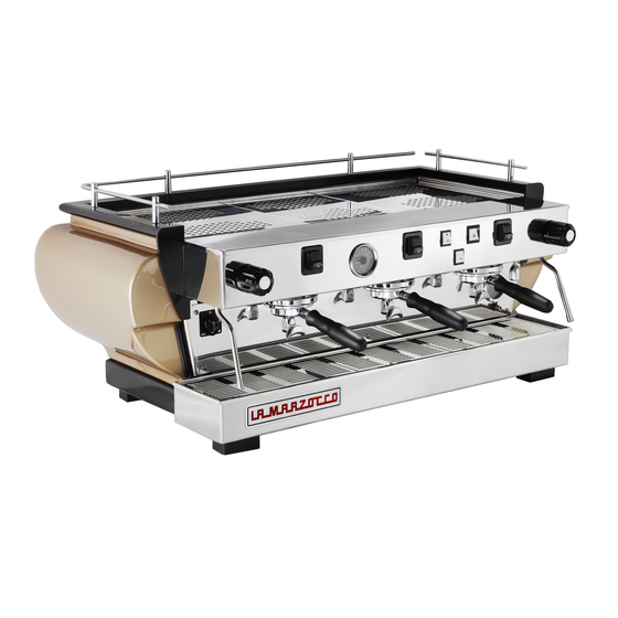
The Linea's straight lines and simple charm occupy many cafes,
roasters and chains, whose names define the industry. The Linea
is the classic La Marzocco machine that has long supported and
helped to develop the specialty coffee industry since the 1990s.
It is a heavy duty workhorse that performs reliably in the highest
volume settings. Tried and true machine, the Linea is perfect for
your new cafe, bar, or restaurant.
Table of Contents

Related Manuals for La Marzocco linea


Summary of Contents for La Marzocco linea
- Page 1 La Marzocco machine that has long supported and helped to develop the specialty coffee industry since the 1990s. It is a heavy duty workhorse that performs reliably in the highest volume settings. Tried and true machine, the Linea is perfect for your new cafe, bar, or restaurant.
-
Page 2: Table Of Contents
& Operating Manual V1.1 - 11/2014 Chapters 1. General Warnings and Safety Specifications page 2 La Marzocco S.r.l. page 4 2. Definition of Available Models Via La Torre 14/H Località La Torre 50038 Scarperia e San Piero 3. Installation... -
Page 3: General Warnings And Safety Specifications
1. General Warnings and Safety Specifications 5) Check to see that data on the rating that they are exclusively of the kind which WARNING plate correspond to those of the mains conforms to current safety regulations, THIS MACHINE IS FOR PROFESSIONAL USE electrical supply to which the machine will being careful not to exceed the power and ONLY AND SHOULD BE INSTALLED IN LOCA-... - Page 4 (as described in the preceding point) COMMON DIMENSIONS AND WEIGHTS FOR and close the water supply tap. Do not CAUTION attempt to repair it, and contact qualified THE LINEA SERIES AS ALREADY MENTIONED IN THE PRECEDING and authorized professionals. Any repairs LINEA 1 gr...
-
Page 5: Definition Of Available Models
2. Definition of Available Models This operating manual refers exclusively to the following models, of our own manufacture: EE Model, AV Model, PADDLE Model with 1, 2, 3 and 4 groups Legend Main Switch Hot water switch Group lever Water level sight glass Manual fill switch Steam knob Pressure gauge... - Page 6 General description 25’ approximately. Operating pressure used to hold the ground coffee; the The models AV, EE and PADDLE are built is maintained by a pressure switch. The espresso flows from the group, through in the 1, 2, 3 and 4 group versions and water boiler has various fittings used for a spout, into the cup(s) after the brewing are essentially composed of the following...
- Page 7 Legend Main Switch Water level sight glass Pressure gauge Coffee groups Coffee dispensing control panel (AV model) Cup warmer switch (non-UL machines) Hot water switch Manual fill switch Steam nozzle/wand Steam knob Hot water nozzle Manual brew switch General Description The AV model machine is built in the 1, 2, 3, and 4 group versions and is essentially composed of the same parts as EE model.
-
Page 8: Installation
3. Installation Legend 380/220/200 Volt cable 220/200 Volt cable Water tubing Drain tubing Main Switch Expansion valve Drain piping Group cover Terminal Bleed screw Motor pump PID Temperature Controller Filter outlet Switch (not provided) Filter inlet Plug (not provided) Connectors Drain wells not provided WARNING... - Page 9 MODELS “EE” “AV” and “PADDLE” → Single/Three phase 220VAC - 50/60 WARNING 1, 2, 3 and 4 groups Hz electrical connection with ground, HAZARDOUS VOLTAGE DISCONNECT FROM protected receptacle and approved circuit POWER SUPPLY BEFORE SERVICING 1) Accessories breaker Check the package to make sure that the 2) Water supply connection →...
- Page 10 a) Power supply cord water supply line and the filtration system in order to eliminate any residual particles • This is the main power supply cable that which could otherwise get stuck in taps or provides power to the entire espresso valves thus preventing them from working machine.
-
Page 11: Machine Operation And Coffee Preparation
Connect the other end to a suitable waste 4. Machine Operation and Coffee Preparation water collection system. In case such a system is not available, and if Once installation has been completed, you inflowing water will compress the air in acceptable according to local regulations, can proceed to hook up the filter holders the boiler it will be necessary, in order to... - Page 12 2) STEAM BOILER the boiler itself switches on the heating CAUTION elements in order to bring the water By turning the main switch (part 1) to DO NOT REMOVE THE FILTER HOLDER WHILE contained in such boiler up to operating position “1”, the automatic fill system RELATIVE GROUP IS BREWING HOT LIqUIDS.
- Page 13 group from right to left (part 1) thus delivered onto the ground coffee, already allowing coffee to be brewed; when you set in the filter and the portafilter, which have obtained your desired amount of is measured through a water volume coffee, return the paddle handle back to control system, which is located above original position on the right-hand side,...
- Page 14 N.B. flow within the factory-set time of the You may press the same button again in The programs for the first group from the electronic module. order to terminate coffee brewing before left will become the default programs for 2. insufficient water flow through the its programmed stop.
-
Page 15: Pid Temperature Controller
GENERAL NOTIONS FOR PREPARING high as 11-12 bar; this may occur any IMPORTANT COFFEE time that, while activating the groups, The temperature of the water in the When the machine has reached its the motor pump forces cold water into coffee boiler, and therefore of the groups, operating pressure, 1.2 - 1.5 bar which the coffee boiler at a pressure of 8-9 bar... - Page 16 5. PID Temperature controller Description Front display description: SV lamp Display Coffee boiler element Pilot light N.B. Auto-tuning/self-tuning lamp In 1,2,3 group machines the PID Controller is installed on left side. In 4 group machines on left and right side. PV: Process Value: measured temp Keys Keys...
- Page 17 Basic operations How to set and display the values: Press the SEL key to display the value * For more detailed information on the potential of this device, consult the: PXR3_Fuji_Micro_controller_Manual.pdf One press to increase the value by 1. Press and hold this key to increase to For further assistance you may contact the After Sales Department: desired value then wait a few seconds to automatically exit programming function.
-
Page 18: Dispensing Steam And Hot Water
6. Dispensing Steam and Hot Water STEAMING MILK In order to prevent part of the liquid to DISPENSING HOT WATER be heated from being sucked back into In order to allow for any condensed water You can obtain hot water by using the the boiler (due to a possible temporary in the wand to be released ALWAYS allow fixed nozzle (fig. -
Page 19: Maintenance And Periodic Cleaning Operations
7. Maintenance and periodic cleaning operations • Make one cup of coffee in order to WARNING CAUTION remove any unpleasant flavour. NEVER REMOVE THE FILTER HOLDER WHEN THE MACHINE MUST BE INSTALLED SO THAT WATER IS BEING DELIVERED. THIS OPERATION Cleaning the drain collector qUALIFIED TECHNICAL PERSONNEL CAN CAN BE ExTREMELY DANGEROUS SINCE THE... - Page 20 remove it by unscrewing the retainer ply is connected) clockwise, or reduce it If the machine has not been used for screw, then soak in espresso detergent by turning the screw counter-clockwise. more than 8 hours or, in any case, after powder.
-
Page 21: De-Commissioning And Demolition
8. De-commissioning and demolition Start by setting the main switch (part 1) to Current regulations make it illegal to dis- the "0" position. card such machine by leaving it on public grounds or on any private property. Disconnecting from the power outlet In case the machine is connected through Recycling notice: the plug (part 24), make sure that the... -
Page 22: Mandatory Maintenance And Check-Up Operations
8. Mandatory maintenance and check-up operations These operations are in addition to the Maintenance and Periodic Cleaning Operations as specified in Chapter 7. The following maintenance and check-up operations sould be carried out by a qualified technician. N.B. These periodic maintenance operations are not covered by warranty. EVERY THREE MONTHS If MP Model: ▪... - Page 24 & Manuale d’uso V1.1 - 11/2014 Capitoli 1. Avvertenze Generali e Norme di Sicurezza pag. 2 La Marzocco S.r.l. pag. 4 2. Definizione dei Modelli Trattati Via La Torre 14/H Località La Torre 50038 Scarperia e San Piero 3. Installazione pag.
- Page 25 1. Avvertenze Generali e Norme di sicurezza ATTENZIONE non devono essere lasciati alla portata dei idonea. bambini, in quanto fonti di pericolo, né È sconsigliabile l'uso di adattatori, prese L’USO DI QUESTA MACCHINA È DI TIPO STRETTAMENTE PROFESSIONALE. LA devono essere dispersi nell'ambiente. multiple e/o prolunghe.
- Page 26 (come descritto al precedente MISURE E PESI COMUNI ALLA punto chiudere l'alimentazione SERIE LINEA 9) In caso di malfunzionamenti o guasti dell'acqua e, per la sua sostituzione, dell'apparecchio procedere a disinserirlo LINEA 1 gr rivolgersi...
- Page 27 2. Definizione dei modelli trattati Il presente manuale d'uso si riferisce esclusivamente ai seguenti modelli di nostra costruzione: Mod. EE, Mod. AV e Mod. PADDLE ad 1, 2, 3 e 4 erogatori Legenda Interruttore generale Interruttore erogazione acqua calda Leva gruppo Oblò...
- Page 28 Descrizione generale in circa 25'. Il mantenimento della pressione sul quale si innesta il portafiltro nella quale Le macchine modello EE e PADDLE sono di esercizio è realizzato da un pressostato. si mette la dose di caffè in polvere e dal disponibili nelle versioni con 1, 2, 3 e 4 Sulla caldaia sono applicati vari raccordi quale tramite il beccuccio l'espresso scende...
- Page 29 Legenda Interruttore generale Oblò del livello acqua Manometro Gruppi erogazione caffè Pulsantiera erogazione caffè (modello AV) Interruttore scaldatazze (macchine non-UL) Interruttore erogazione acqua calda Interruttore riempimento manuale Lancia per vapore Manopola per erogazione vapore Lancia acqua calda Descrizione generale Interruttore erogazione manuale La macchina modello AV viene costruita nelle versioni con 1, 2, 3 e 4 erogatori ed è...
- Page 30 3. Installazione Legenda Cavo da 380/220/200 Volt Cavo da 220/200 Volt Tubo acqua Tubo di scarico Interruttore generale Valvola di espansione Tubi di scarico Copertura gruppo Terminale Vite di sfiato Elettropompa Regolatore di temperatura PID Uscita filtro Interruttore (non fornito) Ingresso filtro Spina (non fornita) Rubinetto...
- Page 31 • Il rubinetto di arresto dell'acqua potabile stessa, garantendo una elevata qualità della • 1 fascetta fermatubo e gli interruttori terminali della linea di bevanda erogata, è opportuno che l’acqua corrente elettrica dovranno trovarsi nella in ingresso abbia durezza superiore a 9°f ATTENZIONE posizione più...
- Page 32 Cavo alimentazione motore pompa e 4 gruppi erogatori fissato alla macchina da caffè dell'acqua 3) Collegamento elettrico espresso tramite connettore provvisto di serra- Questa è la linea di alimentazione per il ATTENZIONE cavo. motore della pompa dell'acqua. L'elettronica PRIMA DI EFFETTUARE EVENTUALI interna accenderà...
- Page 33 parte della fornitura. Collegare un'estremità 4. Messa in funzione e preparazione del caffè del tubo di plastica rinforzato al raccordo del tubo di scarico presente sul lato sinistro Eseguite le operazioni di installazione, si Poiché l'acqua entrando nella caldaia della macchina da caffè espresso, fissarlo innestano sotto ai gruppi i portafiltri (fig.
- Page 34 2) CALDAIA VAPORE la resistenza elettrica per riportare a giusta ATTENZIONE Mettendo l'interruttore generale part. 1 temperatura l'acqua in essa contenuta. NON TOGLIERE MAI IL PORTAFILTRO in posizione “1”, automaticamente entrerà Tuttavia, in questo caso, è necessario QUANDO IL RELATIVO GRUPPO È IN FASE in funzione l'autolivello che azionando registrare la valvola di espansione part.
- Page 35 caffè desiderata, riportare la maniglia alla Premesse con il simbolo della spirale per più di 4 secondi. posizione di partenza, sul lato destro. In Il sistema di dosaggio del caffè è basato sul volume dell'acqua che arriverà in erogazione corrispondenza della suddetta posizione la sulla polvere del caffè, già...
- Page 36 funzione di interruttore per l'erogazione 1. Macinazione troppo fine e quindi Per effettuare diminuzioni dell'erogazione continua e arresto della stessa. erogazione del caffè troppo lenta (goccia a non prevista nella programmazione si può goccia o quasi) per cui il ventolino non è in premere nuovamente il tasto inizialmente N.B.
- Page 37 INFORMAZIONI GENERALI Per ottenere una buona bevanda è PREPARAZIONE DEL CAFFÈ importantissimo, oltre ovviamente al Quando la macchina ha raggiunto la pressione tipo di miscela, il grado di macinazione di esercizio di 1,2 - 1,5 Bar riscontrabile del caffè. La macinazione ideale si trova sulla scala in alto del manometro (part.
- Page 38 5. Regolatore di temperatura PID Descrizione Descrizione display Spia SV Display Spia d'accensione caldaia caffè frontale: N.B. Spia autoregolazione Nelle macchine a 1,2,3 erogatori il termostato è installato sul lato sinistro. Nelle macchine a 4 erogatori si trova, invece, su entrambi i lati.
- Page 39 Operazioni di base Come impostare e visualizzare i valori: Premere il tasto SEL per visualizzare il valore * Per maggiori informazioni sulle potenzialità di questo dispositivo, consultare: PXR3_Fuji_Micro_controller_Manual.pdf Premere una volta per aumentare di 1 il valore. Per ulteriore assistenza, contattare il Dipartimento Post vendita di La Premere e tenere premuto questo tasto Marzocco: per aumentare il valore, quindi attendere...
- Page 40 6. Erogazione di vapore e acqua calda PREPARAZIONE DEL LATTE Ad evitare che una eventuale momentanea EROGAZIONE DI ACQUA CALDA decompressione della caldaia possa cau- Prima di OGNI utilizzo di vapore procedere Prelevare acqua calda tramite la lancia fissa sare una parziale aspirazione del liquido con una erogazione a vuoto per garantire part.11 fig.
- Page 41 7. Manutenzione e pulizia periodica • Fare un caffè in modo da eliminare i sapori ATTENZIONE ATTENZIONE sgradevoli. NON TOGLIERE MAI IL PORTAFILTRO LA MACCHINA DEVE ESSERE INSTALLATA IN QUANDO VIENE EROGATA ACQUA. QUESTA MODO TALE DA PERMETTERE AL PERSONALE Pulizia della bacinella di scarico OPERAZIONE È...
- Page 42 può avvenire che piccoli residui di polvere di diminuirla girando la vite in senso antiorario; la cicli di lavaggio prima di compiere erogazioni caffè vadano pian piano ad ostruire, anche regolazione deve essere effettuata con almeno al fine di sfruttare le massime potenzialità parzialmente, la reticella di infusione.
- Page 43 8. Messa fuori servizio e demolizione Preventivamente portare in posizione “0” l’abbandono della macchina sul suolo l'interruttore generale part. 1. pubblico o in qualsiasi altro luogo proprietà di terzi. Scollegamento dell'alimentazione elettrica Nel caso di collegamento tramite spina part. Avviso di riciclaggio: 24 assicurarsi anche che l'interruttore part.
- Page 44 9. Operazioni programmate di manutenzione e di controllo Queste operazioni si aggiungono alle Operazioni di Manutenzione e Pulizia Periodica come specificato nel Cap. 7 Le seguenti Operazioni di manutenzione e di controllo dovranno essere eseguite periodicamente da personale tecnico qualificato. N.B.
- Page 46 & Manuel de Fonctionnement V1.1 - 11/2014 Chapitres 1. Instructions Génerales et Mesures de Sécurité page 2 La Marzocco S.r.l. page 4 2. Définition des Modèles Traités Via La Torre 14/H Località La Torre 50038 Scarperia e San Piero 3.
- Page 47 1. Instructions Générales et Mesures de Sécurité laissé à la portée des enfants, en raison du en vigueur, n’oubliant jamais de respecter la ATTENTION danger potentiel qu'il représente, ni être puissance indiquée sur l’adaptateur et sur les CETTE MACHINE SERT UNIQUEMENT À UN dispersé...
- Page 48 être faite par la maison de fabrication ou POIDS ET MESURES COMMUNES À LA SÈRIE par un centre autorisé qui n’utilisera que de AVERTISSEMENT LINEA pièces de rechange d’origine. L’inobservance de toutes ces normes peut compromettre la COMME ON VIENT DE DIRE DANS LES NOTES...
- Page 49 2. Definition des modeles examines Nous vous rappelons que cette notice d’utilisation se refère uniquement aux modèles de notre fabrication suivants: Mod. EE, Mod. AV et Mod. PADDLE avec 1, 2, 3 et 4 groupes de distribution de café Légende Interrupteur général Interrupteur pour la distribution d’eau chaude Levier groupe...
- Page 50 Description générale d’environ 25 minutes. Le maintien de la pression de café moulu, et, après avoir mis en marche la Les modèles AV, EE et PADDLE sont fabriqués d’exercice est réalisé au moyen d’un pressostat. distribution, c’est du porte-filtre, à travers son bec, dans les versions avec 1, 2, 3 et 4 groupes de Sur la chaudière vous trouverez plusieurs que vous verrez s’écouler le café...
- Page 51 Légende Interrupteur général Hublot du niveau visible de l’eau Manomètre Groupes de distribution de café Panneau de commandes pour la distribution du café (Modèle AV) Interrupteur pour le chauffage des tasses (machines non UL ) Bouton-poussoir pour la distribution d’eau chaude Interrupteur de remplissage manuel Bec à...
- Page 52 3. Installation Legende Câble à 380/220/200 Câble à 220/200 Tuyau eau Tuyau de vidange Interrupteur Général Valve d'expansion Conduite d'écoulement Couvercle groupe Borne Vis de purge Électropompe Régulateur de Température PID Sortie épurateur Interrupteur Entrée épurateur Prise Robinet Connecteurs Petits puits non fourni ATTENTION LA MACHINE À...
- Page 53 MODELS “EE” “AV” et “PADDLE” protégée et disjoncteur homologué ATTENTION 1, 2, 3 et 4 groupes de distribution → Raccordement électrique monophasé TENSION DANGEREUSE DÉbRANCHER DE 200VAC - 50/60 Hz avec terre, prise 1) Accessoires L'ALIMENTATION ÉLECTRIQUE AVANT DE protégée et disjoncteur homologué PROCÉDER À...
- Page 54 résidus qui autrement pourraient se déposer a) Cordon d'alimentation dans les logements des robinets et des vannes • Il s'agit du câble d'alimentation principal en compromettant leur juste fonctionnalité. qui alimente toute la machine espresso. Il y a Relier le raccord de la distribution d’eau potable différents types de câbles qui se basent sur les de la machine espresso à...
- Page 55 4. Mise en marche et préparation du café de la machine espresso, le fixer avec le collier "bloque-tuyau" inclus. Raccorder l'autre extrémité à un système de collecte des eaux Après avoir terminé les opérations d’installation, la chaudière ira tout de suite comprimer l’air usées approprié.
- Page 56 2) CHAUDIERE VAPEUR Distribution lors de la première installation AVERTISSEMENT Positionnez l’interrupteur général (1) sur Une fois que les procédures de première le numéro “1”. L’autoniveleur se mettra installation reportées précédemment sont NE PAS ENLEVER LE PORTE-FILTRE PENDANT automatiquement en marche et actionnera terminées et avant de procéder aux distributions QUE LE GROUPE CORRESPONDANT DISTRIbUE DES LIQUIDES CHAUDS.
- Page 57 désirée aura été obtenue, remettre le manche bride qui fixe le groupe à la chaudière. Chaque on n’appuie sur aucune touche. Il faudra du paddle dans sa position originale à droite, à compteur contient un élément tournant (qu’on alors répéter l’opération précédente pour les ce moment-là...
- Page 58 groupe séparément, de gauche à droite. Distribution du café Chaque touche joue aussi le rôle d’interrupteur Prendre un porte-filtre et mettre un peu de d’arrêt, donc il est possible d’arrêter la café moulu dans le filtre: une dose pour le distribution d’un café...
- Page 59 NOTICE GÉNÉRALE POUR LA jugerez nécessaire (il est conseillé d’employer PRÉPARATION DU CAFÉ au minimum 7 gr.). La mouture idéale est celle qui permet un écoulement régulier de Lorsque la machine a atteint la pression la boisson sortant du petit bec du porte-filtre; d’exercice, de 1,2 - 1,5 Bar qu’on peut relever l’écoulement ne devra être ni trop lent ni trop en haut du manomètre (3, ill.
- Page 60 5. Régulateur de température PID Description Description de Voyant lumineux résistance chaudière-café 1 6 Voyant SV 2 Affichage l’affichage avant: N.B. 5 Voyant accord automatique/autoréglage Sur les machines à 1,2,3 groupes le Régulateur de Tempéra- ture PID est installé sur le côté gauche. Sur les machines à 4 *** PV: Valeur réelle mesurée en entrée groupes sur le côté...
- Page 61 à la valeur désirée puis at- PXR3_Fuji_Micro_controller_Manual.pdf tendre quelques secondes pour sortir automa- tiquement de la fonction de programmation. Pour plus d’assistance appeler le Service d’après-vente de La Marzocco, Une pression pour diminuer la valeur de 1. [email protected] Presser et maintenir enfoncée cette touche [email protected] pour diminuer à...
- Page 62 6. Distribution de Vapeur et Eau Chaude POUR FAIRE MOUSSER LE LAIT Afin d’éviter qu’une partie du liquide à chauf- DISTRIBUTION D’EAU CHAUDE fer ne soit aspirée dans la chaudière (à cause Avant CHAQUE utilisation de vapeur procéder à Il est possible d’obtenir de l’eau chaude en uti- d’une possible décompression temporaire à...
- Page 63 7. Opérations d’entretien et de nettoyage périodique • Préparer un café de façon à faire disparaître AVERTISSEMENT ATTENTION toute saveur désagréable. N’ENLEVEZ JAMAIS LE PORTE-FILTRE PENDANT CETTE MACHINE DOIT ÊTRE INSTALLÉE DE Nettoyage de la cuvette de décharge QU’IL EST EN PHASE DE DISTRIbUTION. CETTE FAçON À...
- Page 64 partiellement, le filet d’infusion (de la petite aiguilles d’une montre la vis du by-pass (qui prévoir des cycles de lavage avant d’accomplir douche). Pour procéder à son nettoyage, il se trouve au-dessous du bouchon situé à des distributions afin d’exploiter les capacités faut d'abord l'enlever en dévissant sa vis de côté...
- Page 65 8. Mise hors de service et démolition Tout d’abord mettez l’interrupteur général (1) Il est strictement interdit par la loi d’abandonner à “0”. la machine sur le sol public ou dans un endroit quelconque appartenenat à autrui. Mise hors tension Si le branchement est réalisé...
- Page 66 9. Opérations programmées de maintenance et de contrôle Ces opérations viennent s’ajouter aux opérations d’Entretien et de Nettoyage Périodique telles que spécifiées au Chapitre 7 Les Opérations suivantes de Maintenance et de Contrôle doivent être effectuées périodiquement par le personnel technique qualifié. N.B.
- Page 68 & Betriebsanleitung V1.1 - 11/2014 Kapitel 1. Allgemeine Hinweise und Sicherheitsvorkehrungen Seite 2 La Marzocco S.r.l. Seite 4 2. Definition der Vorhandenen Modelle Via La Torre 14/H Località La Torre 50038 Scarperia e San Piero 3. Installation Seite 7 (Firenze) - ITALIA 4.
- Page 69 1. Allgemeine Hinweise und Sicherheitsvorkehrungen schaum und sonstiges) sollen weder in Reichweite fachsteckern oder/und Verlängerungen ist nicht zu ACHTUNG von Kindern gelassen werden noch in der Umwelt empfehlen. Falls nicht anders möglich, nur Stecker, DIESE MASCHINE IST NUR FÜR verstreut werden, da sie Ursache von Gefahren Adapter oder Verlängerungen, die den geltenden PROFESSIONELLEN EINSATZ GEDACHT UND darstellen.
- Page 70 Personal wenden. 9) Im Falle eines Nicht-Funktionierens oder von VORSICHT Störungen des Gerätes, das selbige vom Stromnetz IN DER SERIE „LINEA” ÜBEREINSTIMMENDE abtrennen (wie im vorherigen Punkt beschrieben) WIE SCHON IN DEN VORHERIGEN HINWEISEN MASSE UND GEWICHTE ANGEGEBEN, KANN DER HERSTELLER NICHT und den Hahn der Wasserversorgung schließen.
- Page 71 2. Definition der vorhandenen Modelle Die vorliegende Bedienungsanleitung bezieht sich ausschließlich auf folgende Modelle unserer Produktion: Modell EE, Modell AV und Modell PADDLE mit 1, 2, 3 und 4 Gruppen Legende Hauptschalter Ausgabeschalter für heißes Wasser Gruppenhebel Schauglas des sichtbaren Wasserniveaus Manueller Füllschalter Dampfknebel Manometer...
- Page 72 Allgemeine Beschreibung für die „Dienste” von Heißwasser und für das gestrichenem Stahl und aus Inox-Stahl. Die Die Geräte Modelle AV, EE und PADDLE werden in Hauptanschlusskabel angebracht. Struktur ist Ergebnis besonderer Studien um die den Versionen mit 1, 2, 3 und 4 Ausgabeventilen ästhetische Funktion, um die ergonometrischen 2.
- Page 73 Legende Hauptschalter Schauglas des sichtbaren Wasserniveaus Manometer Gruppe des Kaffees Schaltertafel der Kaffeeausgabe(AV-Modell) Knopf zum Vorheizen der Tassen (nicht-UL-Maschinen) Ausgabeknopf für heißes Wasser Manueller Füllschalter Stahlröhrchen für Wasserdampf Schalter für Dampfausgabe Stahlröhrchen zur Heißwasserausgabe Manueller Ausgabeschalter Allgemeine Beschreibung Das Gerät Modell AV wird in den Versionen mit 1, 2, 3 und 4 Ausgabeventilen hergestellt und ist weitgehend wie das Modell EE konstruiert.
- Page 74 3. Installation Legende Kabel für 380/220/200 Kabel für 220/200 Wasserleitung Abwasserleitung Hauptschalter Expansionsventil Abflussleitung Gruppenabdeckung Klemme Entlüftungsschraube Motorpumpe Temperaturregler PID Wasserreiniger-Auslauf Schalter Wasserreiniger-Einlauf Steckdose Hahn Stecker Abflüsse nicht enthalten ACHTUNG DIE KAFFEEMASCHINE WAAGRECHT AUF EINER nicht THEKE AUFSTELLEN, DIE MINDESTENS 80CM VOM enthalten BODEN ENTFERNT IST REINIGUNGSGERÄT...
- Page 75 DIE MODELLE “EE”, “AV” und “PADDLE” Elektroanschluss mit geerdetem, geschütztem 2) Anschluss an das Wasserversorgungsnetz 1, 2, 3 und 4 Gruppen Klemmenbrett genehmigtem Z u m A n s c h l u s s d e r M a s c h i n e a n d a s Leistungsschalter Wasserversorgungsnetz, befolgen Sie die im Kapitel 1) Zubehörteile...
- Page 76 Wasserpumpe an den Ausgang des eventuellen mit einem Zugentlastungsverbinder an der b) Netzkabel für Wasserpumpenmotor Wasserfilters/-aufbereiters an. Espressomaschine befestigt Es handelt sich dabei um das Netzkabel für den Anmerkung: Stellen Sie sicher, dass während → 380 VAC 3 Phasen 5-Leiterkabel mit 2,5/6 Wasserpumpenmotor.
- Page 77 4. Inbetriebnahme und Kaffeezubereitung Nach Durchführung Installation 1. KESSEL „KAFFEE” Abb. 4) entfernen und ein wenig den kleinen Filterrahmen mit den dazugehörigen Filtern (Abb. Der Eingang des Wassers in den saturierten Bolzen (21), Entlüftungsschrauben genannt, 5) von links nach rechts drehend unter die Gruppen Kessel (Kaffee) erfolgt sofort nach Öffnung der losschrauben, so dass die Luft austritt, und muß...
- Page 78 2) KESSEL „DAMPF” Abgabe nach der ersten Installation Zum Modell EE - Abb. 1 Indem man den Hauptschalter (1) in Position „1” Nach Beendigung der oben beschriebenen Vorgänge Nehmen Sie einen Siebträger und geben Sie etwas stellt, tritt automatisch der Selbstausgleichsapparat für die erste Installation und vor der Abgabe von gemahlenen Kaffee in das Sieb: die empfohlenen zu in Funktion, der durch seine Betätigung der...
- Page 79 Portion in die Tasse fließt, danach schalten Sie ab, Das Flügelrädchen ist derart vorbereitet, dass es weitere Ausgaben programmiert; indem Sie den Paddelgriff in die Ausgangsstellung frei mit dem Wasserfluß dreht und zwei Signale 2. Für die anderen drei Druckknöpfe werden die auf der rechten Seite zurück bringen.
- Page 80 Zeit von mehr als 3-4 Sekunden keine Signale an 2 Tassen, normal oder „hoch”. das Steuergehäuse sendet, beginnt das LED des betätigten Druckknopfes aufzuleuchten. Dies bedeutet, dass: A) irgend etwas am Wassereingang beim Flügelrädchen und folglich bei der Kaffeeausgabe nicht funktioniert, was folgende Ursachen zu Um nicht in der Programmierung vorgesehene Grunde liegend haben könnte: Verringerungen der Ausgabe vorzunehmen, kann...
- Page 81 ALLGEMEINE HINWEISE ZUR ZUBEREITUNG Der geeignetste Mahlgrad ist derjenige, der eine DES KAFFEES gleichmässige Ausgabe der Getränkes aus dem Wenn das Gerät den Betriebsdruck von 1,2 - 1,5 Bar, Ausguß des Filterrahmens ermöglicht: weder zu ablesbar auf der oberen Skala des Manometers (3, langsam noch zu schnell.
- Page 82 5. Temperaturregler PID Beschreibung Beschreibung des Displays auf Kontrollleuchte Kaffeebrühelement 1 6 Leuchte für EW 2 Display der Vorderseite: N.B. 5 Leuchte für Auto-Abstimmung/ In Maschinen mit 1,2,3 Gruppen ist der PID Controller auf Selbstabstimmung der linken Seite installiert. In Maschinen mit 4 Gruppen befindet er sich auf der rechten und linken Seite.
- Page 83 Sie einige Sekunden, um automatisch die controller_Manual.pdf Programmierfunktion zu verlassen. Für zusätzliche Unterstützung können Sie sich an die Nachverkaufsabteilung der Fa. La Marzocco wenden, [email protected] Einmal drücken, um den Wert um 1 zu mindern. [email protected] Drücken Sie diese Taste und halten Sie sie gedruckt, um den gewünschten Wert zu mindern, danach...
- Page 84 6. Dampf- und Heißwasserausgabe MICHZUBEREITUNG Um zu vermeiden, dass Teil der zu erwärmenden HEISSWASSERAUSGABE Vor JEDER Dampfverwendung öffnen Sie Flüssigkeit zurück in den Boiler gesaugt wird Mit der festen Düse (Abb. 1 oder 3) zwischen der die Dampfdüse, um sicherzustellen, dass das (aufgrund von eventuellem Druckabfall im Gruppe ganz links und der Dampfdüse (Teil 9, Abb.
- Page 85 7. Wartung und regelmäßige periodische Reinigung • Bereiten Sie eine Tasse Kaffee, um jeglichen ACHTUNG VORSICHT unangenehmen Geschmack zu entfernen. DIE MASCHINE MUSS SO INSTALLIERT WERDEN, NIEMALS DEN FILTERRAHMEN ENTFERNEN, Reinigung der Abwasserfangschale DASS SIE FÜR qUALIFIZIERTE TECHNIKER FÜR WENN SICH DIESER IN AUSGABEPHASE BEFINDET.
- Page 86 vorkommen, dass kleine Kaffeepulverrückstände Deckels, wo die Speisung der Pumpe verbunden Wenn die Maschine länger als 8 Stunden nicht benützt nach und nach zu einer Verstopfung, vielleicht ist) im Uhrzeigersinn dreht, und absenken, indem wird und auf alle Fälle wenn sie längere Zeit stillsteht, teilweise, Infusion-Filtergewebes man die Schraube im entgegengesetzten Sinn...
- Page 87 8. Außerbetriebnahme und Abbau Aus Vorsichtsgründen den Hauptschalter (Detail 1) Recyclinghinweis auf die Position „0” stellen Umweltschutzhinweis Alte Elektrogeräte nicht über den Hausmüll Abtrennung der Elektroversorgung entsorgen. In dem Falle der Verbindung mittels Stecker (24) Bitte leisten Sie Ihren Beitrag zum Umweltschutz soll man sich versichern, dass der Schalter (23) vor und zur Schonung der Ressourcen.
- Page 88 9. Programmierte wartungs- und kontrollvorgänge Diese Vorgänge ergänzen die in Kapitel 7 aufgeführten Vorgänge für Wartung und Periodische Reinigung. Die folgenden Wartungs- und Kontrollvorgänge sind regelmäßig durch qualifizierte Fachtechniker durchzuführen. N.B. Diese periodischen Wartungseingriffe sind nicht durch die Garantie abgedeckt. ALLE DREI MONATE Bei AV-Modell: ▪...
- Page 90 & Guía sobre el Funcionamiento V1.1 - 11/2014 Capítulos 1. Advertencias Generales y Normas de Seguridad pàg. 2 La Marzocco S.r.l. pàg. 4 2. Definición de los Modelos Tratados Via La Torre 14/H Località La Torre 50038 Scarperia e San Piero 3.
- Page 91 1. Advertencias generales y normas de seguridad poliestirol, etc.) no los debe dejar al alcance resulta necesario el uso exclusivo de enchufes, ATENCIÓN de los niños, ya que pueden ser peligrosos, ni adaptadores y alargadores que cumplan las ESTA MÁQUINA ES SÓLO PARA USO abandonarlos en el ambiente.
- Page 92 (como se ha descrito en el punto anterior) y MEDIDAS Y PESOS COMUNES A LA SERIE LINEA cierre el grifo de suministro de agua. Renuncie ATENCIÓN a cualquier tentativo de reparación y diríjase...
- Page 93 2. Definición de los modelos tratados El presente manual de uso se refiere exclusivamente a los siguientes modelos de nuestra construcción: Mod. EE, Mod. AV y Mod. PADDLE a 1, 2, 3 y 4 erogatorios Leyenda Palanca de grupo Interruptor general Interruptor para la erogación de agua caliente Llave para erogación del vapor Ventanilla del nivel de agua...
- Page 94 Descripción general 25’. El mantenimiento de la presión se realiza de haber accionado el mando de erogación. Las máquinas modelos AV, EE y PADDLE se gracias a un aparato que conserva los niveles 4. Cubierta construyen en diferentes versiones con 1, 2, 3 constantes.
- Page 95 Leyenda Interruptor general Ventanilla del nivel de agua Manómetro Grupos de erogación de café Pulsadores para la erogación de café (Modelo AV) Interruptor del calienta-tazas (máquinas no UL) Pulsador para la erogación de agua caliente Interruptor llenado manual Suministrador de vapor Mando para la erogación de vapor Suministrador de agua caliente Descripción general...
- Page 96 3. Instalación Leyenda Cable 380/220/200 Voltions Cable 220/200 Voltions Tubo agua Tubo de descarga Interruptor principal Válvula de expansión Tubos de drenaje Cubierta del grupo Terminal Tornillo de purga Bomba a motor Controlador de Temperatura PID Salida purificador Interruptor Entrada purificador Enchufe Grifo Conectores...
- Page 97 El grifo de cierre del agua potable y los 15°f (150ppm, 8.4°d), pH entre 6,5 y 8,5 y una para conexiones hidráulicas interruptores terminales de la linea cantidad de cloruros disueltos inferior a 50 mg/l. • 1,5 mt. de tubo de plástico reforzado para de la corriente eléctrica, tendrán que...
- Page 98 filtro/depurador. 200/220VAC, sección transversal ATENCIÓN Nota: Asegúrese de que haya siempre 2,5/4/6/10 mm2 o AWG 12/10/8 (para la LA BOMBA A MOTOR DEBE ESTAR UBICADA suministro de agua mientras funciona la versión UL), asegurado a la máquina exprés CERCA DE LA MÁQUINA EN UN LUGAR bomba;...
- Page 99 4. Puesta en funcionamiento y preparación del café Realizadas las operaciones de instalación, se 1. CALDERA DE CAFÉ todos los grupos erogatorios (vea el siguiente colocan debajo de los grupos de erogación los La entrada de agua a la caldera (café) tiene diagrama).
- Page 100 sumergida en la caldera. cada uno de los grupos y girándolos como se Para el modelo EE - fig. 1 describe en el manual de uso. Luego, erogar Tome un portafiltro y coloque un poco NOTA: agua durante 2 minutos como mínimo de cada de café...
- Page 101 la taza. Luego, apagar volviendo a colocar la El ventolino está colocado de modo tal que anteriormente elaborada; manija en su posición original, hacia la derecha. puede girar libremente con el paso del agua y 2. repita las fases para los otros tres botones enviar n°...
- Page 102 3-4 segundos, el signo del pulsante presionado comenzará a enviar señales luminosas. Esto significa que: A) algo no funciona en la llegada de agua al ventolino y, por lo tanto, al café. Las causas podrían ser: Para llevar cabo disminución 1.
- Page 103 INFORMACIóN GENERAL PARA LA con los grados de moledura que se pretenden PREPARACIóN DE CAFÉ utilizar para cada taza (el mínimo aconsejado Cuando la máquina llega a una presión de es de 7 gr.) 1,2 - 1,5 Bar, verificable sobre la escala La moledura idónea es aquella que permite que está...
- Page 104 5. Controlador de Temperatura PID Descripción Descripción de Luz piloto de la caldera del café 1 6 Lámpara SV 2 Visor la pantalla frontal: Nota 5 Lámpara de ajuste automático/auto En las máquinas de 1, 2, 3 grupos, el controlador PID está instalado a la izquierda.
- Page 105 Operaciones básicas Cómo definir y visualizar los valores: Pulse el botón SEL para visualizar el valor * Para informaciones mas detalladas sobre las potencialidades de este aparato consultar: Pulse una vez para aumentar el valor en 1 PXR3_Fuji_Micro_controller_Manual.pdf Mantenga pulsado este botón para aumentar el valor deseado;...
- Page 106 6. Erogación de Vapor y Agua Caliente CALENTAR LA LECHE CON VAPOR temporal dentro del tanque de la caldera), lo EROGACIóN DE AGUA CALIENTE Antes de CADA uso de vapor, realizar una cual haría que el vapor y el líquido que salen Usted puede obtener agua caliente usando la erogación en vacío para garantizar la descarga de la boquilla, parte 9, y boquilla parte 11,...
- Page 107 7. Operaciones de manutención y limpieza periódica • Haga una taza de café para eliminar el sabor ATENCIÓN ATENCIÓN desagradable. NO QUITE NUNCA EL PORTAFILTROS LA MÁQUINA SE DEBE INSTALAR DE FORMA Limpieza de la cubeta de descarga CUANDO SE ENCUENTRE EN FASE DE TAL QUE EL PERSONAL CALIFICADO Cada noche, al cierre, quite la rejilla donde TRABAJO.
- Page 108 tornillo de fijación, luego déjela en remojo en que realizarse con, al menos, un grupo en Si la máquina permanece inactiva por un período solución detergente. proceso de erogación de café. superior a 8 horas o después de períodos prolongados de inactividad, es necesario prever IMPORTANTE ciclos de lavado antes de realizar la erogación Accionando la bomba eléctrica por medio...
- Page 109 8. Conclusión del servicio y demolición Como método de prevención ponga en Aviso de Reciclaje: posición “0” el interruptor general (part.1) Advertencia para la Protección del Ambiente: Desconexión de la alimentación eléctrica Los viejos aparatos eléctricos son materiales En caso de conexión mediante enchufe (part. pregiados, no caben dentro de la abitual basura 24) asegúrese de que el interruptor (part.
- Page 110 9. Operaciones programadas de manutención y de control Estas operaciones son adicionales a las Operaciones de Mantenimiento y Limpieza Periódicas, que se especifican en el Capítulo 7. Las siguientes Operaciones de manutención y de control deberán ser efectuadas periódicamente por personal técnico cualificado.