Quick Links
SERVICE MANUAL
REAR PROJECTION TELEVISION
2
2005
YA173
1
PRECAUTION. . . . . . . . . . . . . . . . . . . . . . . . . . . . . . . . . . . . . . . . . . . . . . . . . . . . . . . . . . . . . . . . . . . . . . . . . 1-3
2
SPECIFIC SERVICE INSTRUCTIONS . . . . . . . . . . . . . . . . . . . . . . . . . . . . . . . . . . . . . . . . . . . . . . . . . . . . . . 1-5
3
DISASSEMBLY . . . . . . . . . . . . . . . . . . . . . . . . . . . . . . . . . . . . . . . . . . . . . . . . . . . . . . . . . . . . . . . . . . . . . . 1-10
4
ADJUSTMENT . . . . . . . . . . . . . . . . . . . . . . . . . . . . . . . . . . . . . . . . . . . . . . . . . . . . . . . . . . . . . . . . . . . . . . . 1-20
5
TROUBLESHOOTING . . . . . . . . . . . . . . . . . . . . . . . . . . . . . . . . . . . . . . . . . . . . . . . . . . . . . . . . . . . . . . . . . 1-59
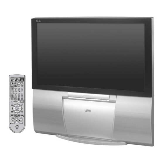
AV-48P775
AV-56P775
AV-56P785
POWER
TV CATV VCR DVD
ASPECT
MULTI SCREEN
TWIN
INDEX
SELECT
SLEEP
FREEZE
SWAP
ML/MTS
DISPLAY
+
INPUT
1
2
3
D/A
4
5
6
i.LINK MENU
7
8
9
RETURN+
TIMER
TUNE
0
TV
THEATER
VIDEO
SUB
FAVORITE
PRO
STATUS
CHANNEL
SUB
NATURAL
SOUND
CINEMA
LIGHT
C.C.
MUTING
GUIDE
CH
VOL
VOL
OK
CH
MENU
BACK
VCR CHANNEL
VCR DVD
PREV NEXT
POWER
TV VCR
REW
PLAY
FF
REC
STOP
PAUSE
OPEN CLOSE
STILL PAUSE
RM-C14G
TABLE OF CONTENTS
COPYRIGHT © 2005 Victor Company of Japan, Limited
,
/H
,
/H
/H
[ AV-56P775 ]
BASIC CHASSIS
RP
No.YA173
2005/2

Related Manuals for JVC AV-48P775/H


Summary of Contents for JVC AV-48P775/H
-
Page 1: Table Of Contents
SERVICE MANUAL REAR PROJECTION TELEVISION YA173 2005 AV-48P775 AV-56P775 AV-56P785 BASIC CHASSIS POWER TV CATV VCR DVD ASPECT MULTI SCREEN TWIN INDEX SELECT SLEEP FREEZE SWAP ML/MTS DISPLAY INPUT i.LINK MENU RETURN+ TIMER TUNE THEATER VIDEO FAVORITE STATUS CHANNEL NATURAL SOUND CINEMA LIGHT... - Page 2 SPECIFICATION Contents Items AV-56P775 AV-48P775 AV-56P785 Dimensions (W × H × D) 120.0cm × 118.9cm × 62.2cm 136.8cm × 129.6cm × 66.7cm (47-1/4" × 46-7/8" × 24-1/2") (53-7/8" × 51-1/8" × 26-3/8") Mass 76 kg ( 168 lbs ) 83 kg ( 183 lbs ) TV RF System (Analog / Digital) Analog : CCIR (M) Digital : ATSC terrestrial / Digital cable...
-
Page 3: Precaution
SECTION 1 PRECAUTION SAFETY PRECAUTIONS (1) The design of this product contains special hardware, many (10) Isolation Check (Safety for Electrical Shock Hazard) circuits and components specially for safety purposes. For After re-assembling the product, always perform an isolation continued protection, no changes should be made to the original check on the exposed metal parts of the cabinet (antenna design unless authorized in writing by the manufacturer. - Page 4 INSTALLATION 1.2.1 INSTALLATION SITE (1) The rear of this set is provided with ventilation openings. Install the set more than 5 cm from a wall and in a location (more than 5cm) with good ventilation. (2) Avoid the following types of locations. a) Unstable locations (location must be able to withstand heavy weight).
-
Page 5: Specific Service Instructions
SECTION 2 SPECIFIC SERVICE INSTRUCTIONS FEATURES • Rear Projection HDTV with built-in ATSC tuner. • New chassis design enable use of an interactive on screen control. • 3-2 PULL DOWN : You can enjoy DVD movies at the highest picture quality. •... - Page 6 REMOTE CONTROL UNIT [RM-C14G] POWER key ASPECT key (16:9 / 4:3) VCR / DVD switch (Set to VCR for SERVICE) POWER TV CATV VCR DVD ASPECT TV / CATV switch (Set to TV for SERVICE) MULTI SCREEN TWIN INDEX SELECT SLEEP MULTI SCREEN operation keys [ TWIN, INDEX, SELECT, FREEZE &...
- Page 7 TECHNICAL INFORMATION 2.4.1 MAIN MICRO COMPUTER (CPU) FUNCTION (MN102H75K) Pin No. Pin name Function Pin No. Pin name Function LED_ONTIMER Lighting for on temer LED ATSC_RX ATSC serial communication [ON TIMER ON:H] / VSYNC V.sync for OSD CONVER_RXD Convergence control LB_PRO Low B protection detection [Error : H] CONVER_TXD...
- Page 8 MAIN PARTS LOCATION 2.5.1 PWB ASS'Y ARRANGEMENT The PWB ASS'Y is indicated below. PWB ASS'Y name AV-48P775HA AV-56P775HA AV-56P785HA 1. MAIN PWB ASS'Y SRP-1009A-M2 SRP-1010A-M2 SRP-1011A-M2 ← ← 2. MI-COM & DIST MODULE PWB ASS'Y SRP0D009A-M2 ← ← 3. POWER PWB ASS'Y SRP-9009A-M2 ←...
- Page 9 SCREEN HANDLING CAUTIONS 2.6.1 SCREEN STORAGE Store the SCREEN ASS'Y in a standing position in order to avoid deformation. If the screen is stored horizontally, there is risk of deforming the screen face. When necessary to place the SCREEN ASS'Y horizontally, position the screen side upwards and sure to place spacers between the screen and resting site (floor or stand etc.) to prevent the screen from sagging.
-
Page 10: Disassembly
SECTION 3 DISASSEMBLY DISASSEMBLY PROCEDURE • Make sure that the power cord is pull out from the AC wall (x2) outlet. FRONT 3.1.1 SPEAKER GRILLE SPEAKER SPEAKER (1) Remove 2 screws [A] from rear side. WIRE (2) The SPEAKER GRILLE bottom is pull out to the front, and 4 claws which are fixing the SPEAKER GRILLE are (x4) FRONT... - Page 11 3.1.6 SCREEN ASS'Y • Take out the SPEAKER GRILLE. (Front view) • Take out the FRONT CONTROL BOX. SCREEN ASS'Y (1) Disconnect the connector [CN00Z]. FRONT (2) Remove 4 screws [A] attaching the SCREEN ASS’Y. (3) Remove 10 screws [B] from rear side. (4) Take out the SCREEN ASS'Y.
- Page 12 3.1.9 REAR PANEL (1) Remove 8 screws [A]. FRONT (2) Remove 4 screws [B]. (3) Take out the REAR PANEL. REAR COVER NOTE : • Before the rear panel is inserted into the cabinet, release the short-circuit between the [SB] connector [1] and [2] pin of the DIGITAL INPUT MODULE PWB.
- Page 13 3.1.12 MAIN UNIT • Take out the SPEAKER GRILLE. • Take out the FRONT PANEL. MAIN UNIT • Take out the REAR PANEL. (1) Remove 4 screws [A] from front side. (2) Disconnect the connector [CN00Z]. FOCUS PACK CN00Z (3) Remove 2 screws [B] attaching the MAIN CHASSIS and BODY.
- Page 14 3.1.16 MAIN CHASSIS 3.1.19 SD CARD PWB • Take out the REAR PANEL. • Take out the REAR PANEL. (1) Remove 2 screws [A]. • Take out the MAIN CHASSIS. (2) Pull out the MAIN CHASSIS for backside. (1) Remove 3 screws [F]. (2) Disconnect the connector [CN1001] on the SD CARD NOTE : PWB.
- Page 15 3.1.23 PROJECTION UNIT • Take out the SPEAKER GRILLE. • Take out the FRONT CONTROL BOX. (x4) PROJECTION UNIT FRONT • Take out the REAR PANEL. • Take out the MAIN UNIT. (1) Take out the CRT SOCKET PWB. REMOTE SENSOR PWB (2) Remove 4 screws [A].
- Page 16 MEMORY IC REPLACEMENT 3.2.1 MEMORY IC This memory IC stores data for proper operation of the video and SERVICE MENU deflection circuits. When replacing, be sure to use an IC containing this (initial value) data. 1.PICTURE/SOUND 7.CONVER B 2.YC SEP 8.IP 3.WHITE BALANCE 9.DSD...
- Page 17 3.2.4 FACTORY SETTING VIDEO STATUS MEMORY (NTSC / 480i / 480p) Setting value Item COLOR TINT COLOR PICTURE BRIGHT DETAIL TEMPERATURE STANDARD THEATER HIGH DYNAMIC GAME HIGH VIDEO STATUS MEMORY (720p / 1080i) Setting value Item COLOR TINT COLOR PICTURE BRIGHT DETAIL TEMPERATURE...
- Page 18 SHIPPING FACTORY SETTING (USER SETTING) Setting item Setting value Setting item Setting value POWER TINT / COLOR / PICTURE/ Refer to setting of Video status CHANNEL CABLE-02 BRIGHT / DETAIL memory at shipping factory VOLUME setting INPUT COLOR TEMPERATURE DIG. NOISE CLEAR VSM (Velocity Scan Modulation) DISPLAY NATURAL CINEMA...
- Page 19 REPLACEMENT OF CHIP COMPONENT 3.3.1 CAUTIONS (1) Avoid heating for more than 3 seconds. (2) Do not rub the electrodes and the resist parts of the pattern. (3) When removing a chip part, melt the solder adequately. (4) Do not reuse a chip part after removing it. 3.3.2 SOLDERING IRON (1) Use a high insulation soldering iron with a thin pointed end of it.
-
Page 20: Adjustment
SECTION 4 ADJUSTMENT ADJUSTMENT PREPARATION (1) You can make the necessary adjustments for this unit with SETTING POSITION either the Remote Control Unit or with the adjustment tools Setting item Setting position and parts as given below. VIDEO STATUS STANDARD (2) Adjustment with the Remote Control Unit is made on the TINT / COLOR / PICTURE / basis of the initial setting values, however, the new setting... - Page 21 BASIC OPERATION OF SERVICE MENU SERVICE MENU 1.PICTURE/SOUND 7.CONVER B 2.YC SEP 8.IP 3.WHITE BALANCE 9.DSD 4.MEMORY SETUP 0.HDMI 5.RF AFC 6.CONVER A DO NOT ADJUST 1.PICTURE/SOUND 5.RF AFC NTSC FULL ST L FL MUTE TOO HIGH GOOD TOO LOW TUNER MAIN FINE...
- Page 22 4.4.1 TOOL OF SERVICE MENU OPERATION Operate the SERVICE MENU with the REMOTE CONTROL UNIT. 4.4.2 SERVICE MENU ITEMS In general, basic setting (adjustments) items or verifications are performed in the SERVICE MENU. 1.PICTURE / SOUND This sets the setting values of the VIDEO, AUDIO and DEFLECTION circuits. 2.YC SEP This is used when the YC SEPARATION circuit is adjusted.
- Page 23 4.4.5 SERVICE MENU SETTING 1. PICTURE/SOUND 3. WHITE BALANCE AUDIO / VIDEO / DEFLECTION circuit adjustment. Adjustment of LOW LIGHT / HIGH LIGHT. 1. SETTING ITEM No. 1. SELECT ITEM • Press [CH+] / [CH-] key : AUDIO 2. SETTING VALUE : SIGNAL BRIGHT : DEFLECTION...
- Page 24 6. CONVER A 8. IP Setting the CONVERGENCE PHASE adjustment. DIST circuit data setting. • Setting for 6.CONVER A is described in the CONVERGENCE [Do not adjust] adjustment. 8.IP 6.CONVER A SETTING ITEM No. NTSC FULL ST L FL MUTE CPA01~CPA11 SETTING ITEM No.
- Page 25 INITIAL SETTING VALUE OF SERVICE MENU (1) Adjustment of the SERVICE MENU is made on the basis of the initial setting values; however, the new setting values which set the screen in its optimum condition may differ from the initial setting. (2) Do not change the initial setting values of the setting items NOT LISTED IN ADJUSTMENT.
- Page 26 VIDEO SYSTEM ( NTSC / 480i ) NTSC 480i Item Item name Variable range STANDARD THEATER STANDARD THEATER 48" 56" 48" 56" 48" 56" 48" 56" S01 COLOR 000~255 S02 TINT 000~255 ( 480p / 720p / 1080i ) 480p 720p / 1080i Item Item name...
- Page 27 ( NTSC / 480i ) NTSC 480i STANDARD THEATER STANDARD THEATER Item Item name Variable range HIGH HIGH HIGH HIGH 48" 56" 48" 56" S10 DRIVE R 000~255 (Not display) -128 ~ +127 +004 +006 +014 +005 +006 +014 S12 DRIVE B 000~255 (Not display) -128 ~ +127...
- Page 28 ( ATSC ) ATSC Item Item name Variable range 480i 480p 720p / 1080i STANDARD THEATER STANDARD THEATER STANDARD THEATER S31 COL OFST -128~+127 +005 +005 +006 +003 S32 TNT OFST -128~+127 -003 -003 -003 -003 -003 -003 ( TWIN / FREEZE / ATSC ) ATSC TWIN / FREEZE Item...
- Page 29 Item Item name Variable range Initial setting value S55 EETH BRT -128~+127 S56 EETH CNT -128~+127 S57 BREE CNT 000~031 S58 DKEE CNT 000~031 S59 DREE BRT 000~127 S60 BREE ACL 000~255 S61 DKEE ACL 000~255 S62 VMOFF DE -128~+127 +002 S63 VM LOW -128~+127...
- Page 30 DEFLECTION SYSTEM Item SINGLE PICTURE Item name Variable range TWIN / INDEX (FULL) D01 V. SIZE 000~127 D02 EW 000~063 D03 H. SIZE 000~063 D04 V. SCORE 000~063 D05 V. LINE 000~063 D06 V. CENT 000~063 D07 EW.TRAP 000~063 D08 BOT.CORN 000~015 D09 TOP.CORN 000~015...
- Page 31 OTHERS Initial setting value ASPECT Item Item Item name Variable range Item name Variable range CINEMA OTHERS 48P775 56P775 56P785 F01 E 1 000~255 F09 AUTOSCR1 000~015 F02 E 2 000~255 F10 AUTOSCR2 000~015 (Not display) 000~255 F11 AUTOSCR3 000~015 (Not display) 000~255 F12 AUTOSCR4...
- Page 32 4.5.2 [2.YC SEP] (All fixed) Variable Initial setting Item No. Item name NOTE : range value Initial setting value is reference value at following condition. YCM039 (Not display) 000~127 INPUT SIGNAL : NTSC YCM040 (Not display) 000~003 ASPECT : FULL YCM041 (Not display) 000~063...
- Page 33 Variable Initial setting Variable Initial setting Item No. Item name Item No. Item name range value range value YCM084 (Not display) 000~063 YCM129 (Not display) 000 / 001 YCM085 (Not display) 000 / 001 YCM130 (Not display) 000~003 YCM086 (Not display) 000 / 001 YCM131 (Not display)
- Page 34 Variable Initial setting Variable Item No. Item name Item No. Item name Fixed value range value range YCM174 (Not display) 000~255 YCS032 (Not display) 000~003 YCM175 (Not display) 000 / 001 YCS033 (Not display) 000 / 001 YCM176 (Not display) 000 / 001 YCS034 (Not display)
- Page 35 4.5.3 [3.WHITE BALANCE] Variable Item No. Item name Fixed value range NOTE : Initial setting value is reference value at following condition. YCS077 (Not display) 000 / 001 INPUT SIGNAL : NTSC YCS078 (Not display) 000 / 001 ASPECT : FULL YCS079 (Not display) 000 / 001...
- Page 36 Variable Initial setting Variable Initial setting Item No. Item name Item No. Item name range value range value CBA46 MTPV2 -32768~32767 CBA01 ADD RATIO CBA47 -7~7 CBA02 INTERLACE 0 / 1 CBA48 BL1POSV 0~2047 CBA03 CKOUT FRE CBA49 BL1POSH 0~4095 CBA04 DF MUTE 0 / 1...
- Page 37 Variable Initial setting Variable Initial setting Item No. Item name Item No. Item name range value range value CBA91 PWMH1W 0~4095 IPA033 (Not display) 000 / 001 CBA92 PWMV1P 0~1023 IPA034 (Not display) 000~03F CBA93 PWMV1W 0~1023 IPA035 (Not display) 000 / 001 CBA94 PWMH2W...
- Page 38 Variable Initial setting Variable Initial setting Item No. Item name Item No. Item name range value range value DSA027 (Not display) 000 / 001 DSB001 (Not display) (Not display) DSA028 (Not display) 000~03F DSB002 (Not display) (Not display) DSA029 (Not display) 000 / 001 DSB003 (Not display) (Not display)
- Page 39 Variable Initial setting Variable Initial setting Item No. Item name Item No. Item name range value range value DSB046 (Not display) (Not display) DSC036 (Not display) 000~0FF DSB047 (Not display) (Not display) DSC037 (Not display) 000~00F DSB048 (Not display) (Not display) DSC038 (Not display) 000~0FF...
- Page 40 Variable Initial setting Variable Initial setting Item No. Item name Item No. Item name range value range value HDM008 (Not display) 000 / 001 HDM053 (Not display) 000 / 001 HDM009 (Not display) 000 / 001 HDM054 (Not display) 000 / 001 HDM010 (Not display) 000 / 001...
- Page 41 Variable Initial setting Variable Initial setting Item No. Item name Item No. Item name range value range value RHD016 (Not display) (Not display) RHD061 (Not display) (Not display) RHD017 (Not display) (Not display) RHD062 (Not display) (Not display) RHD018 (Not display) (Not display) RHD063 (Not display) (Not display) RHD019...
- Page 42 Variable Initial setting Variable Initial setting Item No. Item name Item No. Item name range value range value RHD106 (Not display) (Not display) RHD151 (Not display) (Not display) RHD107 (Not display) (Not display) RHD152 (Not display) (Not display) RHD108 (Not display) (Not display) RHD153 (Not display) (Not display) RHD109...
- Page 43 ADJUSTMENT PROCEDURE 4.6.1 CHECK ITEMS Measuring Item Test point Adjustment part Description instrument X-RAY Resistor S1 connector (1) Receive NTSC whole black signal. PROTECTOR [6.8kΩ 2 pin : X-Ray2 (2) Connect resistor 6.8kΩ (1/4W, ±34Ω) between 2 pin check 1/4W ±34Ω] 3 pin : X-Ray1 &...
- Page 44 4.6.3 FOCUS & BEAM SPOT ADJUSTMENT Measuring Item Test point Adjustment part Description instrument FOCUS & Signal TEST MODE (1) Receive NTSC crosshatch signal. BEAM SPOT generator [5.CONVER OFF] (2) Select FULL mode with [ASPECT] key. adjustment (3) Select DYNAMIC mode with [VIDEO STATUS] key. Similar R Def.
- Page 45 4.6.4 DEFLECTION & CONVERGENCE ADJUSTMENT • The adjustment using the remote control unit is made on the basis of the initial setting values. • The setting values which adjust the screen to the optimum condition can be different from the initial setting values. •...
- Page 46 4.6.4.2 PREPARATION Measuring Item Test point Adjustment part Description instrument SCREEN TILT Signal TEST MODE • Confirm correct FOCUS adjustment. (1) Receive NTSC crosshatch signal. adjustment generator [5.CONVER OFF] (2) Enter TEST MODE [5.CONVER OFF]. (3) Select crosshatch pattern with [INPUT] key. Remote G DEF.
- Page 47 4.6.4.3 DEFLECTION ADJUSTMENT Measuring Item Test point Adjustment part Description instrument V. POSITION / Signal [1.PICTURE/SOUND] • To memorize every time after finish adjustment on each V.SIZE / generator D01 : V. SIZE mode. V.LINEARITY D05 : V. LINE (1) Receive NTSC circle pattern signal. adjustment Remote D06 : V.
- Page 48 Measuring Item Test point Adjustment part Description instrument SIDE PIN Signal [1.PICTURE/SOUND] (1) Receive NTSC crosshatch signal. adjustment generator D02 : EW (2) Select FULL mode with [ASPECT] key. D08 : BOT.CORN (3) Select 1. PICTURE/SOUND from SERVICE MENU. Remote D09 : TOP.CORN (4) Select <...
- Page 49 4.6.4.4 CONVERGENCE ADJUSTMENT Measuring Item Test point Adjustment part Description instrument CONVERGENCE Signal [6.CONVER A] NOTE: PHASE generator CPA04 : TPOV OFST Be sure to make it the value of Table1. Supposing data check CPA05 : FINEP differs, correct to the value of Table1. Remote CPA06 : STARTLIN A When data is corrected (when the [MUTING] key is...
- Page 50 Measuring Item Test point Adjustment part Description instrument OVERALL Signal [ 6.CONVER A ] NOTE: CONVERGENCE generator CPA01 : FINE OFF Be sure to make it the value of Table2. Supposing data (LINE) CCA01 : H CENT differs, correct to the value of Table2. check Remote CCA02 : H SIZE...
- Page 51 Measuring Item Test point Adjustment part Description instrument OVERALL Signal [ 7.CONVER B ] NOTE: CONVERGENCE generator Perform this adjustment after performing OVERALL (POINT) CONVERGENCE (LINE) check. adjustment Remote It adjusts displaying and checking adjustment data by control unit the [DISPLAY] key. Adjust in order of area A, area B, area C and area D.
- Page 52 Measuring Item Test point Adjustment part Description instrument AUTO Signal [ 6.CONVER A ] AUTO CONVERGENCE (SUPER FOCUS) PRESET CONVERGENCE generator [ 7.CONVER B ] AUTO CONVERGENCE PRESET is a work in which you (SUPER FOCUS) store (memorize) an optimum reference CONVERGENCE setting Remote in SUPER FOCUS operation in the unit.
- Page 53 4.6.5 VIDEO ADJUSTMENT Measuring Item Test point Adjustment part Description instrument RGB CUTOFF Signal TP-R [1.PICTURE/SOUND] (1) Receive NTSC signal (include 0% or -3% black). adjustment generator [R CRT S14: CUTOF R (2) Select STANDARD mode with [VIDEO STATUS] SOCKET PWB] S16: CUTOF G key.
- Page 54 Measuring Item Test point Adjustment part Description instrument WHITE Signal [3.WHITE BALANCE] NOTE : Before starting the adjustment, warm up the unit for BALANCE generator more than 30 minutes. (LOW LIGHT) CUT R (1) Receive NTSC gray scale signal (include 0% black). adjustment Remote CUT B...
- Page 55 Measuring Item Test point Adjustment part Description instrument SUB BRIGHT Signal [1.PICTURE/SOUND] (1) Receive NTSC signal (include 0% or -2% black). adjustment generator S03: BRIGHT (2) Select STANDARD mode with [VIDEO STATUS] key. (3) Set the COLOR TEMP is LOW mode. Remote (4) Select 1.PICTURE/SOUND from SERVICE MENU.
- Page 56 Measuring Item Test point Adjustment part Description instrument SUB COLOR / Signal TP-R [1.PICTURE/SOUND] [ Method of adjustment without measuring instrument ] SUB TINT / generator [R CRT S01 : COLOR (1) Receive NTSC color bar signal (include 75% white). B-Y GAIN SOCKET PWB] S02 : TINT...
- Page 57 Measuring Item Test point Adjustment part Description instrument SUB COLOR / Signal TP-R [1.PICTURE/SOUND] [ Method of adjustment with measuring instrument ] SUB TINT / generator [R CRT S01 : COLOR (1) Receive NTSC color bar signal (include 75% white). B-Y GAIN SOCKET PWB] S02 : TINT...
- Page 58 4.6.6 AUDIO (MTS) ADJUSTMENT Measuring Item Test point Adjustment part Description instrument MTS INPUT Remote [1.PICTURE/SOUND] (1) Select 1.PICTURE / SOUND from SERVICE MENU. LEVEL control unit A01 : IN LEVEL (2) Select < A01 > (IN LEVEL). check (3) Verify that < A01 > is set at its initial setting value. TV audio AUDIO OUT [1.PICTURE/SOUND]...
-
Page 59: Troubleshooting
SECTION 5 TROUBLESHOOTING SELF-DIAGNOSIS FUNCTIONS • This model has self-check functions that inform of the failure of the TV by detecting abnormality. • Operational state is always monitored and the identified is memorized on the record. Therefore, diagnosis may be prevented against expectations if "NG" are indicated in many items. When recurrence of symptoms can be predicted, erase (reset) the history of failure and allow the unit to again record the results of diagnosis. - Page 60 Indication Check item Details of detection Method of detection Timer The AC power frequency is changed as Periodically check the power frequency by follows : counting the AC pulse and monitor whether or 50Hz → 60Hz not the frequency is changed except for the 60Hz →...
- Page 61 Victor Company of Japan, Limited AV & MULTIMEDIA COMPANY VIDEO DISPLAY CATEGORY 12, 3-chome, Moriya-cho, kanagawa-ku, Yokohama, kanagawa-prefecture, 221-8528, Japan (No.YA173) Printed in Japan...