Table of Contents
Quick Links
D
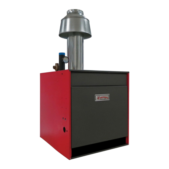
Series 16H
Gas-Fired Natural Draft Hot Water Boilers
INSTALLATION INSTRUCTIONS
These instructions must be affixed on or adjacent to the boiler
Models:
16H-340
•
16H-410
•
16H-460
•
16H-505
•
E S I G N E D
WARNING: Improper installation,
adjustment, alteration, service or
maintenance can cause property
damage, injury, or loss of life.
For assistance or additional
information, consult a qualified
installer, service agency or
the gas supplier. Read these
instructions carefully before
installing.
Manufacturer of Hydronic Heating Products
P.O. Box 14818 3633 I. Street
Philadelphia, PA 19134
www.crownboiler.com
L
T O
E A D
3050579
1
Table of Contents

Related Manuals for Crown Boiler 16H-340


Summary of Contents for Crown Boiler 16H-340
-
Page 1: Installation Instructions
E A D Series 16H Gas-Fired Natural Draft Hot Water Boilers INSTALLATION INSTRUCTIONS These instructions must be affixed on or adjacent to the boiler Models: 16H-340 • WARNING: Improper installation, 16H-410 • adjustment, alteration, service or maintenance can cause property 16H-460 •... - Page 2 IMPORTANT INFORMATION - READ CAREFULLY NOTE: The equipment must be installed in accordance with those installation regulations enforced in the area where the installation is to be made. These regulations shall be carefully followed in all cases. Authorities having jurisdiction shall be consulted before installations are made.
- Page 3 WARNING This boiler requires regular maintenance and service to operate safely. Follow the instructions contained in this manual. Improper installation, adjustment, alteration, service or maintenance can cause property damage, personal injury or loss of life. Read and understand the entire manual before attempting installation, start-up operation, or service.
-
Page 4: Table Of Contents
Table of Contents I. Pre-Installation .............6 II. Boiler Assembly ............8 III. Gas Control System Assembly ........15 IV. Water Trim and Piping ..........19 V. Gas Piping ..............23 VI. Venting ...............25 VII. Electrical ..............28 VIII. System Start-up ............36 IX. Service & Troubleshooting ........42 X. - Page 5 Table 1: Dimensional Data Approx. Recommended Water Dimensions (Inches) Shipping Boiler Chimney Size Content Weight (LB.) Model (Round) (Gallons) Knockdown 16H-340 27-1/2 13-3/4 27-13/16 8” dia. x 15 ft. 15.9 16H-410 31-1/4 15-5/8 30-13/16 8” dia. x 15 ft. 17.9 16H-460 17-1/2 33-1/2 10”...
-
Page 6: Pre-Installation
Our responsibility ceases upon delivery of boiler to carrier in good condition. Any claim 1. Single boiler, 16H-340, Front: 24” (61.0 cm) for damage or shortage in shipment must be filed 2. Single boiler, 16H-410-16H-505, Front: 48”... - Page 7 rating of 1 perm or less with openings gasketed Alternate method for boiler located within confined and sealed, and space. Use indoor air if two permanent openings communicate directly with additional space(s) of b. Weather-stripping has been added on openable sufficient volume such that combined volume of all windows and doors, and spaces meet criteria for unconfined space.
-
Page 8: Boiler Assembly
II. Boiler Assembly Remove Crate 1. Remove all fasteners at crate skid. 2. Lift outside container and remove with all other inside protective spacers and bracing. Remove boiler from skid. See Figure 2. Exercise care to avoid dropping boiler. 1. Place boiler in approximate location. Refer to Section I: Pre-Installation. - Page 9 4. Do not enclose boiler (including special base) on all 5. Fill boiler completely with water by venting air four sides. Models 16H-340 may be enclosed on through purge valve. Close purge valve and apply three sides (alcove) while maintaining clearances water pressure of at least 10 psi but less than 50 psi shown in Figure 4.
- Page 10 Figure 5: General Assembly (Knockdown Boilers) Move boiler to permanent location by sliding or ¼” - 20 x 1¼” carriage bolts, washers and nuts. walking. Do not drop. 2. Seal between top of Base Front Panel and Section Assembly with furnace cement (shipped in Confirm that one (1) Flue Baffle is properly positioned in each Boiler Flueway.
- Page 11 Figure 6: Flame Roll-out Switch Installation Figure 7: Burner/Burner Access Panel Installation...
- Page 12 end of the burner access panel. Models 16H-410- Attach Top Panel to Left Side, Right Side and Upper 16H-505 have two (2) burner access panels. Rear Panels. Remove insulation from notch of right side burner 9. Tighten all jacket screws. access panel only.
- Page 14 Figure 9: EP-CSD-1 Control Installation...
-
Page 15: Gas Control System Assembly
III. Gas Control System Assembly (Knockdown Boilers) EP-CSD-1 Control System EI (Intermittent Ignition) Install Gas Control System. All components are Install Gas Control System. All components are located in Combination Boiler Parts and Control located in Combination Boiler Parts and Control Carton. -
Page 19: Water Trim And Piping
Piping NPT contamination such as: Drop a. Addition of excessive make-up water as a result 20° F 2” 3’ of system leaks. 16H-340 30° F 1½” 2’ 40° F 1¼” 1’ b. Absorption through open tanks and fittings. 20° F 2”... - Page 20 Figure 17: Drain Piping Installation Install Drain Valve in rear of Left End Section, Tapping “G”. See Figure 17. Components are located in Water Trim Carton. Install Temperature-Pressure Gauge. Components are located in Water Trim Carton. 1. Standard Temperature - Pressure Gauge Piping. See Figure 19: Alternate Temperature-Pressure Gauge Figure 18.
- Page 21 entering boiler. See Figure 20. Also, consult I=B=R Crown recommends maintaining temperature Installation and Piping Guide No. 250. differential (drop) across the system at 40°F or less, and return water temperature at minimum of 135°F. 2. If boiler is connected to heating coils located in Continued boiler operation for prolonged periods of air handling units where they may be exposed to time under conditions when temperature differential...
- Page 22 a. A boiler by-pass is recommended for any continuously run below 135°F for extended installation for improved system temperature periods (due to low temperature applications balance, while serving to protect the boiler from like snow melt, heat pump systems or others), sustained condensing operation.
-
Page 23: Gas Piping
Model Size Natural LP / Propane 3. Install sediment trap, ground-joint union and manual shut-off valve upstream of boiler gas valve and 16H-340 136.0 outside jacket. See Figure 22. 16H-410 164.0 4. All above ground gas piping upstream from 16H-460 184.0... - Page 24 Table 6: Maximum Capacity of Schedule 40 Pipe in CFH for Gas Pressures of 0.5 psig or Less Length 0.3 Inch w.c. Pressure Drop 0.5 Inch w.c. Pressure Drop (Feet) ½ ¾ 1¼ ½ ¾ 1¼ 1,050 1,400 Table 7: Equivalent Lengths of Standard Pipe Fittings & Valves Valves (Fully Open) Threaded Fittings Pipe...
-
Page 25: Venting
VI. Venting metal screw) on outside and other two teeth inside Install vent system in accordance with local building Draft Hood skirt. See Figure 23. codes; or local authority having jurisdiction; or National Fuel Gas Code, ANSI Z223.1/NFPA 54, Part 3. - Page 26 2. Where two or more appliances vent into a common Boiler Equipped With Vent Damper. See Figure 24. vent, the area of the common vent should at least 1. Open Vent Damper Carton and remove Installation equal the area of the largest vent plus 50 % of the Instructions.
- Page 27 9. Design vent system for sea level input. venting system are located and other spaces of the building. Turn on clothes dryers and any appliance 10. Provide adequate ventilation of Boiler Room. See not connected to the common venting system. Section I: Pre-Installation.
-
Page 28: Electrical
Jacket Top Panel. 2. Remove factory installed Jumper Plug from Vent Damper Receptacle on Vestibule Wiring Harness and discard. 3. Plug Vent Damper Harness Plug into Vent Damper Receptacle. See Figure 24. Figure 26: Vent Damper Schematic Wiring Diagram (16H-340 - 16H-505) - Page 29 POWER FAILURE - The damper blade will stop in the Vent Damper Sequence of Operation. See Figure 26 position it was in when power failed. (Combustion for schematic wiring diagram (16H-340 - 16H-505). can never take place unless the damper blade is in the fully open position).
- Page 30 Table 10: Sequence of Operation and Wiring Diagrams Wiring Diagram Figure Sequence of Ignition System Country Fuel Boiler Sizes Operation Intermittent Natural Gas Intermittent Ignition 7 - 10 Sect. Figure 31 Page 30 (Honeywell EI - 24V) LP Gas Intermittent Ignition Natural Gas 8 - 10 Sect.
- Page 31 MegaStor Relay MegaStor Figure 31: Wiring Diagram, Honeywell EI, USA, Intermittent Circulation (16H-340 - 16H-510)
- Page 32 ii. Blocked Vent Switch: Automatically 2. Electronically Supervised Intermittent Ignition interrupts main burner operation when (EP-CSD-1) Sequence of Operation excessive flue gas spillage occurs. a. Normal Operation Circulator continues to operate with call for Thermostat or operating control calls for heat.
- Page 33 Figure 35: Wiring Diagram, EP Ignition System, Natural Gas Only, Intermittent Circulation (EP-CSD-1; Natural Gas, USA Only, 16H-410 - 16H-505)
- Page 34 Figure 36: McDonnell & Miller 751P-MT (120V) L.W.C.O. Wiring for Boilers with 24V Limit Circuits (EI) (16H-340 - 16H-505) Figure 37: McDonnell & Miller 751P-MT (120V) L.W.C.O. Wiring for Boilers with 120V Limit Circuits (EP-CSD-1) (16H-410 - 16H-505)
- Page 35 Figure 38: Hydrolevel OEM - 170/550/650/750 (120V) L.W.C.O. Wiring for Boilers with 24V Limit Circuits (EI) (16H-340 - 16H-505) Figure 39: Hydrolevel OEM - 170/550/650/750 (120V) L.W.C.O. Wiring for Boilers with 120V Limit Circuits (EP-CSD-1) (16H-410 - 16H-505)
-
Page 36: System Start-Up
VIII. System Start-Up 9. Close purge valve, continue filling the system WARNING until the pressure gauge reads the desired cold fill pressure. Close fill valve. Completely read, understand and follow all instructions in this manual before attempting (Note - If make-up water line is equipped with start-up. - Page 37 Figure 41: Operating Instructions (EI)
-
Page 38: For Your Safety Read Before Operating
FOR YOUR SAFETY READ BEFORE OPERATING WARNING: If you do not follow these instructions exactly, a fire or explosion may result causing property damage, personal injury, or loss of life. If you cannot reach your gas supplier, call the A. This appliance is equipped with an ignition device fire department. - Page 39 CAUTION Avoid operating this boiler in an environment where saw dust, loose insulation fibers, dry wall dust, etc. are present. If boiler is operated under these conditions, the burner interior and ports must be cleaned and inspected daily to insure proper operation.
- Page 40 Table 12: Input Rate Check thermostat or operating control operation. Raise and lower temperature setting to start and stop Size of Gas Meter Dial Seconds boiler operation. for One One-Half Five Check ignition system shut-off. Revolution Cu. Ft. Cu. Ft. Cu.
- Page 41 opens to 1.4 or 2.5 inch w.c. and steps to full is in full open position. pressure after approximately 30 seconds. Check Install Front Removable Panel. manifold pressure after step has occurred. Adjust gas valve pressure regulator as necessary for 10.0 inches 1.
-
Page 42: Service & Troubleshooting
Do not allow the boiler to operate with altered, disconnected or jumpered components. Only use replacement components identical to those originally supplied by Crown Boiler Company. General. Inspection and service must be conducted 4. - Page 43 Important Product Safety Information Refractory Ceramic Fiber Product Warning: The Repair Parts list designates parts that contain refractory ceramic fibers (RCF). RCF has been classified as a possible human carcinogen. When exposed to temperatures above 1805°F, such as during direct flame contact, RCF changes into crystalline silica, a known carcinogen.
- Page 44 Table 13: Pilot Burner Location clips. Verify Main Burner with Pilot Bracket is in Boiler Model Pilot Located Between Burners* proper location. See Table 13. 16H-340 6 & 7 Lubrication. Manufacturers Instruction should be 16H-410 6 & 7 followed on all parts installed on boiler requiring 16H-460 7 &...
- Page 45 Honeywell EI Ignition Module Yellow LED Flame Codes Yellow LED Indicates Recommended Service Action Flash Code Heartbeat Normal Flame Signal Weak Flame Signal - System will operate reliably but flame signal is less than Perform routine maintenance to desired. assure optimum flame signal. Note: This indication may flash temporarily during or shortly after lightoff on some applications.
- Page 46 Honeywell EI Ignition Module Green LED Status Codes Green LED Flash Code Indicates Next System Action Recommended Service Action (X + Y) No “Call for Heat” None Startup - Flame sense Flash Fast None calibration Heartbeat Normal operation None If system fails to light on next trial for 5 minute Retry Delay- ignition check gas supply, pilot burner, Initiate new trial for ignition after...
- Page 47 Honeywell EI Trouble Shooting Guide...
- Page 48 THIS PAGE LEFT BLANK INTENTIONALLY...
-
Page 49: Repair Parts
X. Repair Parts All Series 16H Repair Parts may be obtained through your local Crown wholesale distributor. Should you require assistance in locating a Crown distributor in your area, or have questions regarding the availability of Crown products or repair parts, please contact Crown Customer Service at: 215-535-8900 or Fax (215) 535-9736. - Page 50 Quantity Item No. Description Part No. 16H-340 16H-410 16H-460 16H-505 1. Heat Exchanger Assembly 6171607 6171608 Complete (Less Flue Baffles) 6171609 6171610 Left End Section 7171601 Intermediate Section 7171603 Right End Section 7171602 80861013 80861034 Tie Rod 80861035 80861036 Washer...
- Page 51 Quantity Item No. Description Part No. 16H-340 16H-410 16H-460 16H-505 2. Canopy 61116071 260128 Canopy 61116091 61116110 Bolt, Carriage, ¼ - 20 x 1” Procure Locally Washer, ¼” Flat Procure Locally Nut, ¼” - 20 Procure Locally...
- Page 52 Quantity Item Description Part No. 16H-340 16H-410 16H-460 16H-505 3. Base Assembly Base End Panel 260660 260647 260648 Base Channel Assembly 260649 260650 260667 260668 Base Rear Panel Assembly 260669 260670 260607 260608 Base Front Panel Assembly 260609 260610 260627...
- Page 53 Item Description Part No. 16H-340 16H-410 16H-460 16H-505 4. Manifold and Main Burners Main Burner 150161 Main burner with Pilot Bracket, Honeywell EI 150160 Main burner with Pilot Bracket, EP 8231603 260157 260158 Manifold 260159 260160 Pipe Plug, 1/8 NPT (Included with 4C)
- Page 54 Part No. Size Quantity 5-3 Gas Train -- Intermittent Ignition (EI) USA: 7 - 10 Section, Natural and LP Gas 16H-340 THRU Gas Valve, Robertshaw 7000DERHC, Natural Gas, 1” NPT 3507310 16H-505 16H-340 THRU Gas Valve, Robertshaw 7000DERHC-LP, LP Gas, 1” NPT...
- Page 55 Item Description Part No. Quantity 5-4 Gas Train -- Intermittent Ignition (EP-CSD-1) USA Only: 8 - 10 Section, Natural Gas Only Gas Valve, Robertshaw 7000GVERHC-S7C, Natural Gas, 1” NPT 81660168 Solenoid Gas Valve, Honeywell V8295A1032, 1” NPT 81660236 Manual Shut-Off Valve, Conbraco #50-403-02, 1” NPT 822615 Leak Test/Shut-Off Valve, Conbraco #50GB501A, 1/8”...
- Page 56 5-6 Pilot Assembly and Piping -- Intermittent Ignition (Honeywell EI) USA 7 - 10 Section, Natural and LP Gas Pilot Burner, Honeywell Q3481B1206, Natural Gas 103704-01 Pilot Burner, Honeywell Q3481B1420, LP Gas 103705-01 16H-340 - 16H-505 Brass Compression Union, 1/4” OD Tube 8236008...
- Page 57 Item Description Part No. Size Quantity 5-9 Pilot Assembly and Piping -- Intermittent Ignition (EP-CSD-1) USA Only: 8 - 10 Section, Natural Gas Only Pilot Burner, Honeywell Q179C1009, Natural Gas 8236017 Flame Rod Lead, Honeywell R1298020, 4 Ft. Lg. 71362561 Rajah Connector, Honeywell 37356 8236021 Ignition Lead, Honeywell R1061012, 3 Ft.
- Page 59 Quantity Item Description Part No. 16H-340 16H-410 16H-460 16H-505 6. Jacket 60416131 60416141 Complete 60416151 60416161 704160793 704160893 Jacket Top Panel 704160993 704161093 7201611 7201613 Jacket Top Panel Main Insulation 7201615 7201617 704160795 704160895 Jacket Upper Rear Panel 704160995 704161095...
- Page 61 Quantity Item Description Part No. 16H-340 16H-410 16H-460 16H-505 6. Jacket (Continued) 72016076 72016086 Jacket Vestibule Panel Lower Insulation Piece 72016096 72016106 704160792 704160892 Jacket Lower Front Tie Bar 704160992 704161092 7201619 7201620 Jacket Lower Rear Panel Insulation 7201621 7201622...
- Page 62 Quantity Item Description Part No. 16H-340 16H-410 16H-460 16H-505 7. Trim and Miscellaneous Controls Limit, 140-220°F, Honeywell L4080D1218 (EI) 35-3300 L4080B1212 (EP) 80160474 Immersion Well, ¾” NPT x 1½” Insul. Depth 35-1010 Optional on EI, Optional on EI, Optional on EI,...
- Page 63 (OPTIONAL: USA: 16H-340 THRU 16H-505) OPTIONAL: 16H-340 THRU 16H-505 (CANADA: 16H-340 ONLY) Quantity Item Description Part No. 16H-340 16H-410 16H-460 16H-505 8. Draft Hood and Automatic Vent Damper 260136 Draft Hood 260138 260139 Automatic Vent Damper, 8” 96-035 Automatic Vent Damper, 9”...
- Page 64 Manufacturer of Hydronic Heating Products P.O. Box 14818 3633 I. Street Philadelphia, PA 19134 PN: 980415 www.crownboiler.com Series 16H Rev 5 - 6/15...