
Related Manuals for Canon imageRUNNER ADVANCE 9070 PRO series


Summary of Contents for Canon imageRUNNER ADVANCE 9070 PRO series
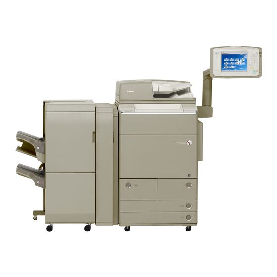
- Page 1 imageRUNNER ADVANCE C9075 PRO/9070 PRO/ 9065 PRO/9060 PRO/C7065/7055 Series Rev. 6.0 Service Manual Digest Periodical Service Adjustment Error Code User Mode Service Mode Parts Replacement and Cleaning Product Overview Upgrading...
- Page 2 This manual is copyrighted with all rights reserved. Under the copyright laws, this manual may changes in the contents of this manual over a long or short period, Canon will issue a new not be copied, reproduced or translated into another language, in whole or in part, without the edition of this manual.
- Page 3 Explanation of Symbols The following rules apply throughout this Service Manual: The following symbols are used throughout this Service Manual. Each chapter contains sections explaining the purpose of specific functions and the relationship between electrical and mechanical systems with reference to the timing of Symbols Explanation Symbols...
-
Page 4: Table Of Contents
Contents Safety Precautions Duplex Color Image Reader-A1 / Color Image Reader-A1----------- 3-154 Paper Deck Unit – A1 ---------------------------------------------------------- 3-155 CDRH Act -----------------------------------------------------------------------0-2 POD Deck Light – A1 ---------------------------------------------------------- 3-155 Laser Safety --------------------------------------------------------------------0-2 Multi-drawer Paper Deck – A1 ----------------------------------------------- 3-156 Handling of Laser System --------------------------------------------------0-2 Buffer Path Unit - F1 ----------------------------------------------------------- 3-157 Turn power switch ON -------------------------------------------------------0-3 Insertion Unit -H1 --------------------------------------------------------------- 3-158... - Page 5 Product Overview DISPLAY ----------------------------------------------------------------------------- 5-3 I/O (I/O display mode) --------------------------------------------------------- 5-140 Specifications ------------------------------------------------------------------7-2 ADJUST --------------------------------------------------------------------------- 5-186 Specifications of main unit ------------------------------------------------------- 7-2 FUNCTION ----------------------------------------------------------------------- 5-280 Productivity (print speed) -------------------------------------------------------- 7-3 OPTION --------------------------------------------------------------------------- 5-325 Paper type --------------------------------------------------------------------------- 7-4 TEST ------------------------------------------------------------------------------- 5-448 Product lineups ----------------------------------------------------------------7-6 COUNTER ------------------------------------------------------------------------ 5-454 Main unit ----------------------------------------------------------------------------- 7-6...
-
Page 6: Safety Precautions
Safety Precautions ■ CDRH Act ■ Laser Safety ■ Handling of Laser System ■ Turn power switch ON ■ Points to Note About Turning Off the Main Power Switch ■ Safety of Toner ■ Notes When Handling a imageRUNNER ADVANCE Lithium Battery C9075 PRO/9070 PRO/9065 ■... - Page 7 CDRH Act Handling of Laser System The Center for Devices and Radiological Health of the US Food and Drum Administration put When servicing the area around the laser assembly, be sure to turn off the main power. into force regulations concerning laser products on August 2, 1976. These regulations apply The machine's covers that can reflect laser light are identified by means of a warning label to laser products manufactured on and after August 1, 1976, and the sale of laser products (Figure).
-
Page 8: Safety Of Toner
Turn power switch ON Safety of Toner The machine is equipped with 2 power switches: main power switch and control panel power About Toner switch. The machine goes on when the main power switch is turned on (i.e., other than in low power The machine's toner is a non-toxic material made of plastic, iron, and small amounts of dye. -
Page 9: Periodical Service
Periodical Service ■ Periodical Service Operation Item... - Page 10 Periodical Service Operation Item ♦: Replacement (Periodical replacement) ●: Replacement (Consumable parts) Δ: Cleaning ×: Lubrication □: Adjustment ■: Inspection Interva Category Part Name Part No Counter Remark Dustproof Glass Cleaning (black) Δ If dirt appears on the image, remove the glass and clean it. Laser Dustproof Glass Cleaning (color) Δ...
- Page 11 ♦: Replacement (Periodical replacement) ●: Replacement (Consumable parts) Δ: Cleaning ×: Lubrication □: Adjustment ■: Inspection Interva Category Part Name Part No Counter Remark Post-secondary Transfer Sensor Δ Δ Use the blower brush. If dirt is obvious, execute cleaning as needed. Patch Sensor Δ...
- Page 12 ♦: Replacement (Periodical replacement) ●: Replacement (Consumable parts) Δ: Cleaning ×: Lubrication □: Adjustment ■: Inspection Interva Category Part Name Part No Counter Remark Fixing Belt Unit Gear × Clean it when replacing the Pressure Belt. Apply the grease by 100mg onto the all circumference of gear teeth. Pressure Belt Unit Gear ×...
-
Page 13: Adjustment
Adjustment ■ Overview ■ When replacing parts ■ When clearing RAM... -
Page 14: Controller System
Overview Procedure of Service part: adjustment • Setting unit: Main Controller PCB 1 + Controller Box Frame + Cooling Fan • Parts number differs on a model basis (speed basis). In this chapter, measures of adjustment when replacing parts in servicing operation are mentioned. - Page 15 Procedure of Procedure of Service part: DDR2-SDRAM (2 pc.) adjustment adjustment • Setting unit: Main Controller PCB 2 + Controller Box Frame Main Controller PCB 2 Controller Box Frame Flash PCB In order to secure the accuracy of connector connection when slotting in, this service part is provided with the PCB being installed to the frame.
-
Page 16: Dc Controller Pcb
Procedure of 3. After Replacing Procedure of 2. When Replacing adjustment 1) After installing the parts, turn ON the main power switch. adjustment 1) Transferring the parts from old PCB to new PCB 2) Restoring the backup data • DDR2-SDRAM (2 pc.) (When option DDR2-SDRAM is installed: 3 pc.) Use the Remote UI. - Page 17 Procedure of 1. Before Replacing Procedure of adjustment Perform the following operations. Be sure to get an approval from the user Caution: When using the Card Reader and imageWARE adjustment beforehand. Accounting Manager 1) Backup of the set/registered data Card ID used for imageWARE Accounting Manager is stored in Use the Remote UI.
-
Page 18: Laser Exposure System
Laser Exposure System Procedure of Caution: Points to Note when Using the System Software-installed adjustment ■ Laser Scanner Unit When using the HDD which was installed the system software of Procedure of parts Refer to Chapter 0, "Removing the Laser Scanner Unit." the other machine (different serial number), be sure to format the replacement HDD after the installation. - Page 19 Procedure of 3) Adjust the Primary Charging Assembly (in the case of dark image at the front Procedure of 4) Adjust the Primary Charging Assembly (in the case of dark image at the rear adjustment side on the test print). adjustment side on the test print).
- Page 20 Procedure of 5) Execute cleaning of the Charging wire in Service Mode (FUNCTION > Procedure of [Measures before replacing the Developing Assembly.] adjustment CLAENING > WIRE-CLN) Duration: approx. 30 sec. adjustment 1) Disable (OFF) the warm-up rotation. 6) Execute the potential control in Service Mode (COPIER > FUNCTION > DPC (COPIER>FUNCTION>INSTALL>AINR-OFF) >...
-
Page 21: Potential Sensor
■ Potential Sensor Procedure of 2) Install the ITB Unit to the main unit. adjustment Procedure of parts Refer to Chapter 0, “After Removing the ITB Cleaning Blade Unit.” NOTE: replacement Purpose to remove the ITB Unit in this procedure is to prevent the Procedure of 1) Install the Primary Charging Rail, which is in the condition of removing the ITB from a damage caused by dropping a part. - Page 22 Procedure of 5) Install the new Potential Control PCB. Procedure of 7) Place the electrode for electric potential sensor check on the Process Unit adjustment • 1 screw adjustment Inner Cover, and clip the metal plate of the hinge area with the clip of the •...
- Page 23 Procedure of 11) With an exclusive tool, block the front door switch. Procedure of 13) When press the [OK] on the display; indication will change from [ACTIVE] adjustment adjustment to [OK!]. Display Adjust Function Option Test Counter Display Adjust Function Option Test Counter...
-
Page 24: Waste Toner Full Sensor
■ ITB Procedure of 1) When replacing the Fixing Belt Unit, be sure to apply grease (Molykote adjustment PG641) to the 3 gears of the Pressure Belt Unit. Procedure of parts Refer to Chapter 0, "Removing the ITB." • Application quantity: 100 mg / 1 gear replacement •... - Page 25 Procedure of 1) When replacing the Pressure Belt Unit, be sure to apply grease (Molykote Procedure of 2) Clean the oil on the contact wheel of the Pressure Belt Position Sensor and adjustment PG641) to the 3 gears of the Fixing Belt Unit. adjustment the oil spilled from the Pressure Belt with lint-free paper.
-
Page 26: When Clearing Ram
When clearing RAM Procedure of 1) Clear the counter. adjustment COPIER > COUNTER > FIXING > FX-CNT COPIER > COUNTER > DRBL-1 > FX-BLT-U/FX-BLT-L When clearing RAM NOTE: When the foregoing counter clear is executed, the following item is Procedure of Before clearing RAM cleared. -
Page 27: Error Code Over View
Error Code ■ Over View ■ Location Code ■ Error Code ■ Jam Code ■ Alarm Code... -
Page 28: Outline
Over View ■ Location Code When jam occurs, pickup location is indicated with the following pickup position code. Outline In the jam display screen, the “P” row corresponds to the pickup position code. Pickup position Pickup position code ■ Outline At Finisher jam/At error avoidance jam/At ADF jam without pickup operation (at SEND, Inbox, etc.) This chapter describes various codes which are displayed when a failure occurs on the... -
Page 29: Error Code
Error Code Detailed Occurance Items Description code code area E000 -0101 Title Pressure belt temperature rise is insufficient at power Error Code Details Description Pressure main thermistor (THM2) temperature does of detection not reach 50 degrees Celsius within 250 seconds after ■... - Page 30 Detailed Occurance Items Description Detailed Occurance Items Description code code area code code area E001 -0002 Title Abnormal temperature rise of fixing subthermistor 1 E001 -0011 Title Fixing main thermistor abnormal temperature rise (circuit (THM1-2) (circuit failure) abnormality) Description Fixing subthermistor 1 (THM1-2) sensed an abnormal Description Fixing main thermistor (THM1-1) detected abnormal high of detection...
- Page 31 Detailed Occurance Items Description Detailed Occurance Items Description code code area code code area E001 -0013 Title Fixing sub thermistor 2 (THM1-3) abnormal temperature E001 -0103 Title Abnormal temperature rise of pressure subthermistor 2 rise (circuit abnormality) (THM4) (circuit failure) Description Fixing sub thermistor 2 (THM1-3) detected abnormal Description...
- Page 32 Detailed Occurance Items Description Detailed Occurance Items Description code code area code code area E001 -0112 Title Pressure sub thermistor 1 (THM3) abnormal temperature E002 -0002 Title Insufficient fixing belt temperature rise 1 rise (circuit abnormality) Description In a warm-up, the temperature of fixing main thermistor Description Pressure sub thermistor 1 (THM3) detected abnormal of detection...
- Page 33 Detailed Occurance Items Description Detailed Occurance Items Description code code area code code area E002 -0003 Title Insufficient fixing belt temperature rise 2 E002 -0004 Title Insufficient fixing belt temperature rise 3 Description In a warm-up, the temperature of fixing main thermistor Description In a warm-up, the temperature of fixing main thermistor of detection...
- Page 34 Detailed Occurance Items Description Detailed Occurance Items Description code code area code code area E002 -0005 Title Insufficient fixing belt temperature rise 4 E002 -0006 Title Insufficient fixing belt temperature rise 5 Description In a warm-up, the temperature of fixing main thermistor Description In a warm-up, the temperature of fixing main thermistor of detection...
- Page 35 Detailed Occurance Items Description Detailed Occurance Items Description code code area code code area E002 -0102 Title Insufficient pressure belt temperature rise 1 E003 -0001 Title Fixing belt abnormally low temperature Description In a warm-up, the temperature of pressure main Description After standby, fixing main thermistor (THM1-1) detected of detection...
- Page 36 Detailed Occurance Items Description Detailed Occurance Items Description code code area code code area E003 -0002 Title Pressure belt abnormally low temperature E003 -0003 Title Perssure belt abnormally low temperature Description After standby, pressure main thermistor (THM2) detected Description After went in standby, Pressure sub thermistor 1 of detection less or equal to 50 degrees Celsius in succession for ten of detection...
- Page 37 Detailed Occurance Items Description Detailed Occurance Items Description code code area code code area E003 -0004 Title Perssure belt abnormally low temperature E004 -0201 Title Fixing belt temperature difference error 1 Description After went in standby, Pressure sub thermistor 2 Description Difference of detected temperature between the fixing of detection...
- Page 38 Detailed Occurance Items Description Detailed Occurance Items Description code code area code code area E004 -0204 Title Pressure belt temperature difference error E004 -0401 Title 12V failure error Description Difference of detected temperature between pressure Description Detected abnormality on the 12V power supply line. of detection sub thermistor 2 (THM4) and pressure sub thermistor 1 of detection...
- Page 39 Detailed Occurance Items Description Detailed Occurance Items Description code code area code code area E004 -0701 Title Relay off state error (circuit failure) E007 -0001 Title Fixing belt full displacement error (Displacement direction is unknown.) Description Detected that the relay is OFF. of detection Description Full displacement of the fixing belt was detected, but the...
- Page 40 Detailed Occurance Items Description Detailed Occurance Items Description code code area code code area E007 -0011 Title Fixing belt displacement failure (front side) E007 -0021 Title Fixing belt displacement failure (rear side) Description It was detected that the fixing belt was displaced to the Description It was detected that the fixing belt was displaced to the of detection...
- Page 41 Detailed Occurance Items Description Detailed Occurance Items Description code code area code code area E007 -0101 Title Fixing belt home position detection error E007 -9902 Title Pressure belt displacement failure (Full displacement of the pressure belt or failure of the pressure belt position Description Fixing belt home position detection error (Failure of the sensor)
- Page 42 Detailed Occurance Items Description Detailed Occurance Items Description code code area code code area E009 -0500 Title Pressure unit pressure release HP search error Measures A-1. Check the connection of the Drum Speed Description The home position for rotation of releasing pressure of Detection PCB (Y) 1/2 (UN20/21).
- Page 43 Detailed Occurance Items Description Detailed Occurance Items Description code code area code code area E012 -0102 Title A. Drum Speed Detection PCB (Y) 1 signal error E012 -0103 Title Drum Speed Detection PCB (Y) 2 signal error (Controller Version 2x.xx or later) Description The signal is not detected for 80 msec or more.
- Page 44 Detailed Occurance Items Description Detailed Occurance Items Description code code area code code area E012 -0201 Title A. Drum Speed Detection PCB (M) 1/2 signal error Measures (Controller Version 2x.xx or later) A-1. Check the connection of the Drum Speed B.
- Page 45 Detailed Occurance Items Description Detailed Occurance Items Description code code area code code area E012 -0202 Title A. Drum Speed Detection PCB (M) 1 signal error E012 -0203 Title Drum Speed Detection PCB (M) 2 signal error (Controller Version 2x.xx or later) Description The signal is not detected for 80 msec or more.
- Page 46 Detailed Occurance Items Description Detailed Occurance Items Description code code area code code area E012 -0301 Title A. Drum Speed Detection PCB (C) 1/2 signal error Measures (Controller Version 2x.xx or later) A-1. Check the connection of the Drum Speed B.
- Page 47 Detailed Occurance Items Description Detailed Occurance Items Description code code area code code area E012 -0302 Title A. Drum Speed Detection PCB (C) 1 signal error E012 -0303 Title Drum Speed Detection PCB (C) 2 signal error (Controller Version 2x.xx or later) Description The signal is not detected for 80 msec or more.
- Page 48 Detailed Occurance Items Description Detailed Occurance Items Description code code area code code area E012 -0401 Title A. Drum Speed Detection PCB (Bk) 1/2 signal error Measures (Controller Version 2x.xx or later) A-1. Check the connection of the Drum Speed B.
- Page 49 Detailed Occurance Items Description Detailed Occurance Items Description code code area code code area E012 -0402 Title A. Drum Speed Detection PCB (Bk) 1 signal error E012 -0403 Title Drum Speed Detection PCB (Bk) 2 signal error (Controller Version 2x.xx or later) Description The signal is not detected for 80 msec or more.
- Page 50 Detailed Occurance Items Description Detailed Occurance Items Description code code area code code area E012 -0501 Title A. ITB Drive Roller Speed Detection PCB 1/2 signal error Measures B. ITB drive motor error A-1. Check the connection of the ITB Drive Roller Speed Detection PCB 1/2 (UN16/17).
- Page 51 Detailed Occurance Items Description Detailed Occurance Items Description code code area code code area E012 -0502 Title A. ITB Drive Roller Speed Detection PCB 1 signal error Measures B. ITB drive motor error A-1. Check the connection of the ITB Drive Roller Speed Detection PCB 1 (UN16).
- Page 52 Detailed Occurance Items Description Detailed Occurance Items Description code code area code code area E012 -0503 Title ITB Drive Roller Speed Detection PCB 2 signal error E012 -2000 Title Rotation error of Drum Motor (Y/M/C/Bk) (M21/23/25/19) and ITB Drive Motor Description The signal is not detected for 80 msec or more.
- Page 53 Detailed Occurance Items Description Detailed Occurance Items Description code code area code code area E013 -0001 Title Waste toner feed screw lock detection error E013 -0002 Title Waste toner full sensor offset adjustment error Description When the waste toner pipe screw lock SW (SW10) Description The sensor sampling result is not within a specified of detection...
- Page 54 Detailed Occurance Items Description Detailed Occurance Items Description code code area code code area E013 -0003 Title Waste toner full sensor error E015 -0001 Title Decurler incoming amount control error 1 Description Output of the waste toner full sensor cannot be detected. Description Change of the decurler HP sensor 1 (PS88) cannot be of detection...
- Page 55 ■ E020 Detailed Occurance Items Description code code area Detailed Occurance Items Description E020 -0082 Title Patch sensor light intensity correction error code code area Description When executing correction of patch sensor light intensity, E020 -0080 Title ITB base light intensity upper limit error of detection the P wave output is not more than 500 and less than Description...
- Page 56 Detailed Occurance Items Description Detailed Occurance Items Description code code area code code area E020 -0124 Title Initial installation patch (Y) density lower limit error E020 -0130 Title Initial installation toner density sensor (Y) output upper limit error Description When executing the developing assembly initial of detection installation mode (COPIER>...
- Page 57 Detailed Occurance Items Description Detailed Occurance Items Description code code area code code area E020 -0134 Title Initial installation patch (Y) density upper limit error E020 -0136 Title Initial installation patch (Y) sampling error Description When executing developing assembly initial installation Description When executing developing assembly initial installation of detection...
- Page 58 Detailed Occurance Items Description Detailed Occurance Items Description code code area code code area E020 -0190 Title Patch (Y) density lower limit error E020 -0191 Title Patch (Y) density upper limit error Description The ATR patch detection output (SigD) is less than 79. Description The ATR patch detection output (SigD) is more than 970.
- Page 59 Detailed Occurance Items Description Detailed Occurance Items Description code code area code code area E020 -01A2 Title Toner density sensor (Y) output upper limit error E020 -0220 Title Initial installation toner density sensor (M) output lower limit error Description The toner density sensor output (Vsig_ind) is less than of detection 247.
- Page 60 Detailed Occurance Items Description Detailed Occurance Items Description code code area code code area E020 -0224 Title Initial installation patch (M) density lower limit error E020 -0230 Title Initial installation toner density sensor (M) output upper limit error Description When executing the developing assembly initial of detection installation mode (COPIER>...
- Page 61 Detailed Occurance Items Description Detailed Occurance Items Description code code area code code area E020 -0234 Title Initial installation patch (M) density upper limit error E020 -0236 Title Initial installation patch (M) sampling error Description When executing developing assembly initial installation Description When executing developing assembly initial installation of detection...
- Page 62 Detailed Occurance Items Description Detailed Occurance Items Description code code area code code area E020 -0290 Title Patch (M) density lower limit error E020 -0291 Title Patch (M) density upper limit error Description The ATR patch detection output (SigD) is less than 79. Description The ATR patch detection output (SigD) is more than 970.
- Page 63 Detailed Occurance Items Description Detailed Occurance Items Description code code area code code area E020 -02A2 Title Toner density sensor (M) output upper limit error E020 -0320 Title Initial installation toner density sensor (C) output lower limit error Description The toner density sensor output (Vsig_ind) is less than of detection 247.
- Page 64 Detailed Occurance Items Description Detailed Occurance Items Description code code area code code area E020 -0324 Title Initial installation patch (C) density lower limit error E020 -0330 Title Initial installation toner density sensor (C) output upper limit error Description When executing the developing assembly initial of detection installation mode (COPIER>...
- Page 65 Detailed Occurance Items Description Detailed Occurance Items Description code code area code code area E020 -0334 Title Initial installation patch (C) density upper limit error E020 -0336 Title Initial installation patch (C) sampling error Description When executing developing assembly initial installation Description When executing developing assembly initial installation of detection...
- Page 66 Detailed Occurance Items Description Detailed Occurance Items Description code code area code code area E020 -0390 Title Patch (C) density lower limit error E020 -0391 Title Patch (C) density upper limit error Description The ATR patch detection output (SigD) is less than 79. Description The ATR patch detection output (SigD) is more than 970.
- Page 67 Detailed Occurance Items Description Detailed Occurance Items Description code code area code code area E020 -03A2 Title Toner density sensor (C) output upper limit error E020 -0420 Title Initial installation toner density sensor (Bk) output lower limit error Description The toner density sensor output (Vsig_ind) is less than of detection 247.
- Page 68 Detailed Occurance Items Description Detailed Occurance Items Description code code area code code area E020 -0424 Title Initial installation patch (Bk) density lower limit error E020 -0434 Title Initial installation patch (Bk) density upper limit error Description When executing the developing assembly initial Description When executing developing assembly initial installation of detection...
- Page 69 Detailed Occurance Items Description Detailed Occurance Items Description code code area code code area E020 -0436 Title Initial installation patch (K) sampling error E020 -0490 Title Patch (Bk) density lower limit error Description When executing developing assembly initial installation Description The ATR patch detection output (SigD) is less than 79.
- Page 70 Detailed Occurance Items Description Detailed Occurance Items Description code code area code code area E020 -0491 Title Patch (Bk) density upper limit error E020 -04A2 Title Toner density sensor (Bk) output upper limit error Description The ATR patch detection output (SigD) is more than 970. Description The toner density sensor output (Vsig_ind) is less than of detection...
- Page 71 ■ E021 to E077 Detailed Occurance Items Description code code area Detailed Occurance Items Description E021 -0201 Title Developing sleeve drive motor (M) error code code area Description The lock signal of the developing sleeve drive motor (M) E021 -0101 Title Developing sleeve drive motor (Y) error of detection...
- Page 72 Detailed Occurance Items Description Detailed Occurance Items Description code code area code code area E021 -0301 Title Developing sleeve drive motor (C) error E021 -0401 Title Developing sleeve drive motor (Bk) error Description The lock signal of the developing sleeve drive motor (C) Description The lock signal of the developing sleeve drive motor (Bk) of detection...
- Page 73 Detailed Occurance Items Description Detailed Occurance Items Description code code area code code area E022 -0001 Title Drum cleaning / waste toner feed drive motor error E022 -0002 Title Drum cleaning / waste toner feed drive motor error Description The lock signal of the drum cleaning/waste toner feed Description Lock signal of Drum cleaning/waste toner feed drive of detection...
- Page 74 Detailed Occurance Items Description Detailed Occurance Items Description code code area code code area E023 -0102 Title Developing stirring motor (Y) error E023 -0202 Title Developing stirring motor (M) error Description Lock signal of Developing stirring motor (Y) (M26)cannot Description Lock signal of Developing stirring motor (M) (M28) cannot of detection be detected for the specified period of time after first...
- Page 75 Detailed Occurance Items Description Detailed Occurance Items Description code code area code code area E023 -0302 Title Developing stirring motor (C) error E023 -0402 Title Developing stirring motor (Bk) error Description Lock signal of Developing stirring motor (C) (M27) cannot Description Lock signal of Developing stirring motor (Bk) (M29) of detection...
- Page 76 Detailed Occurance Items Description Detailed Occurance Items Description code code area code code area E025 -0102 Title Block supply timeout (Y) error E025 -0120 Title Toner container/toner container inserting inlet phase (Y) error Description The toner supply screw rotation sensor cannot detect of detection rotation of the screw.
- Page 77 Detailed Occurance Items Description Detailed Occurance Items Description code code area code code area E025 -01A0 Title Error in Y Toner Container Reciprocation HP Sensor E025 -01B0 Title Error in Y Toner Container Reciprocation HP Sensor (PS11) (PS11) Description Unable to detect the change in the Release Holder Shift Description Unable to detect the change in the Release Holder Shift of detection...
- Page 78 Detailed Occurance Items Description Detailed Occurance Items Description code code area code code area E025 -01C0 Title Error in Y Toner Insertion Inlet Cover Sensor (PS10) E025 -0200 Title Toner bottle motor lock (M) error Description Unable to detect opening of the Toner Insertion Inlet Description Overcurrent of the toner container drive motor was of detection...
- Page 79 Detailed Occurance Items Description Detailed Occurance Items Description code code area code code area E025 -0210 Title Toner container sealing/release holder shift cam HP E025 -02A0 Title Error in M Toner Container Reciprocation HP Sensor sensor timeout (M) error (PS14) Description HP sensor of release holder shift cam cannot detect Description...
- Page 80 Detailed Occurance Items Description Detailed Occurance Items Description code code area code code area E025 -02B0 Title Error in M Toner Container Reciprocation HP Sensor E025 -02C0 Title Error in M Toner Insertion Inlet Cover Sensor (PS13) (PS14) Description Unable to detect opening of the Toner Insertion Inlet Description Unable to detect the change in the Release Holder Shift of detection...
- Page 81 Detailed Occurance Items Description Detailed Occurance Items Description code code area code code area E025 -0300 Title Toner bottle motor lock (C) error E025 -0310 Title Toner container sealing/release holder shift cam HP sensor timeout (C) error Description Overcurrent of the toner container drive motor was of detection detected.
- Page 82 Detailed Occurance Items Description Detailed Occurance Items Description code code area code code area E025 -03A0 Title Error in C Toner Container Reciprocation HP Sensor E025 -03B0 Title Error in C Toner Container Reciprocation HP Sensor (PS17) (PS17) Description Unable to detect the change in the Release Holder Shift Description Unable to detect the change in the Release Holder Shift of detection...
- Page 83 Detailed Occurance Items Description Detailed Occurance Items Description code code area code code area E025 -03C0 Title Error in C Toner Insertion Inlet Cover Sensor (PS16) E025 -0400 Title Toner bottle motor lock (Bk) error Description Unable to detect opening of the Toner Insertion Inlet Description Overcurrent of the toner container drive motor was of detection...
- Page 84 Detailed Occurance Items Description Detailed Occurance Items Description code code area code code area E025 -0410 Title Toner container sealing/release holder shift cam HP E025 -04A0 Title Error in Bk Toner Container Reciprocation HP Sensor sensor timeout (Bk) error (PS8) Description HP sensor of release holder shift cam cannot detect Description...
- Page 85 Detailed Occurance Items Description Detailed Occurance Items Description code code area code code area E025 -04B0 Title Error in Bk Toner Container Reciprocation HP Sensor E025 -04C0 Title Error in Bk Toner Insertion Inlet Cover Sensor (PS7) (PS8) Description Unable to detect opening of the Toner Insertion Inlet Description Unable to detect the change in the Release Holder Shift of detection...
- Page 86 Detailed Occurance Items Description Detailed Occurance Items Description code code area code code area E032 -0001 Title Counter of NE controller is not working E061 -0003 Title Potential control Vd failure Description Disconnection of the count pulse signal is detected Description At the time of measurement of Vd at potential control, of detection...
- Page 87 Detailed Occurance Items Description Detailed Occurance Items Description code code area code code area E073 -0001 Title Host machine interlock failure E075 -0000 Title Steering HP error Description Interlock at 24 V cannot be detected in the condition Description The home position of the steering roller cannot be of detection where all of the front cover, left lower cover, and manual of detection...
- Page 88 Detailed Occurance Items Description code code area E077 -0001 Title Secondary transfer external roller detachment/attachment error Description The secondary transfer roller attachment/detachment HP of detection sensor (PS22) cannot detect the home position within a specified period. Measures 1. Check the connection between the secondary transfer roller attachment/detachment HP sensor (PS22) and the fixing feed driver (UN5).
- Page 89 ■ E100 to E197 Detailed Occurance Items Description code code area Detailed Occurance Items Description E100 -0401 Title Laser scanner motor BD (Bk) error code code area Description The laser scanner motor cannot detect the VLOCK signal E100 -0101 Title Laser scanner motor BD (Y) error of detection and PLOCK signal during BD rotation.
- Page 90 Detailed Occurance Items Description Detailed Occurance Items Description code code area code code area E102 -0301 Title Laser scanner unit (C) EEPROM error E110 -0201 Title Laser scanner motor (M) error Description Laser scanner unit EEPROM failure / Failure of the data Description The laser scanner motor cannot detect the VLOCK signal of detection...
- Page 91 Detailed Occurance Items Description Detailed Occurance Items Description code code area code code area E197 -0000 Title Serial communication error E197 -0006 Title Serial communication error Description Ex serial communication error with the Fixing Feed Driver Description Ex serial communication error with the DC Controller of detection PCB.
- Page 92 Detailed Occurance Items Description Detailed Occurance Items Description code code area code code area E197 -0020 Title Serial communication error E197 -0031 Title Serial communication error Description HOB serial communication (= register serial Description HOB serial communication error in the Drum ITB Driver of detection communication) error with the DC Controller Interface of detection...
- Page 93 Detailed Occurance Items Description code code area E197 -0052 Title Serial communication error Description Ex serial communication error with the Pickup Feed of detection Driver PCB. Measures 1. Check the connection between the Pickup Feed Driver PCB (J1401) and the DC Controller Interface PCB (J1215).
- Page 94 ■ E202 to E280 Detailed Occurance Items Description code code area Detailed Occurance Items Description E227 -0001 Title Power supply (24 V) error code code area Description The 24 V port is turned off at the time of power-on. E202 -0001 Title Scanner home position error of detection...
- Page 95 Detailed Occurance Items Description Detailed Occurance Items Description code code area code code area E227 -0003 Title Power supply (24 V) error E227 -0101 Title Power supply (24 V) error Description The 24 V port is turned off at the time of job completion. Description The 24 V port is turned off at the time of power-on at of detection...
- Page 96 Detailed Occurance Items Description Detailed Occurance Items Description code code area code code area E227 -0103 Title Power supply (24 V) error E247 -0003 Title System error Description The 24 V port is turned off at the time of job completion Description of detection at DADF.
- Page 97 Detailed Occurance Items Description code code area E270 -0002 Title Failure of the horizontal/vertical direction synchronization signal Description The vertical direction synchronization signal (VSYNC) of detection was not sent due to a failure of the horizontal direction synchronization signal (HSYNC), and an image failure occurred or the operation stopped in failure.
- Page 98 ■ E301 to E490 Detailed Occurance Items Description code code area Detailed Occurance Items Description E350 -0003 Title System error code code area Description E301 -0001 Title Front side light intensity failure of detection Description The light intensity amount at front side shading is less Measures Contact each sale company bases of detection...
- Page 99 Detailed Occurance Items Description Detailed Occurance Items Description code code area code code area E400 -0002 Title Failure of communication between the reader controller E407 -0002 Title Failure of the tray up/down motor (M8) PCB (PCB1) and the DADF Description Even when the tray up/down motor (M8) is driven, the Description A reception error occurred in communication between the...
- Page 100 Detailed Occurance Items Description code code area E413 -0012 Title Failure of the DADF detachment motor 2 (M7) Description Even when the DADF detachment motor 2 (M7) is driven, of detection the DADF detachment home position sensor 2 (SR16) is not turned OFF within a specified period.
- Page 101 ■ E500 to E551 Detailed Occurance Items Description code code area Detailed Occurance Items Description E503 -0002 Title A. Error in communication between the finisher - saddle code code area stitcher (Finisher-A1) E500 -0000 Title A. Error in IPC communication(Finisher-A1) B.
- Page 102 Detailed Occurance Items Description Detailed Occurance Items Description code code area code code area E503 -0004 Title A. Inserter communication error (Finisher-B1) E503 -0042 Title Error in communication between the finisher - integration B. Paper Folding Inserter Unit / Inserter Unit unit (Finisher-A1) Communication error (Finisher-B1) Description...
- Page 103 Detailed Occurance Items Description Detailed Occurance Items Description code code area code code area E503 -0062 Title Error in communication between the finisher - paper E505 -0002 Title A. Backup data error (failed data writing) (Document folding unit (Finisher-A1) Insertion Unit-J1/Paper Folding Unit-G1) B.
- Page 104 Detailed Occurance Items Description Detailed Occurance Items Description code code area code code area E514 -8002 Title A. Error in the gripper base motor (Finisher-A1) E514 -8005 Title Error in the gripper motor (Finisher-A1) B. Rear end assist home position error (Finisher-B1) Description The gripper does not come off the position sensor when Description...
- Page 105 Detailed Occurance Items Description Detailed Occurance Items Description code code area code code area E519 -8001 Title Gear change home position error (Finisher-B1) E530 -8002 Title A. Error in the front alignment motor (Finisher-A1) B. Front aligning plate home position error (Finisher-B1) Description The gear change home position sensor does not turn of detection...
- Page 106 Detailed Occurance Items Description Detailed Occurance Items Description code code area code code area E531 -8002 Title A. Error in the staple motor (Finisher-A1) E532 -8001 Title A. Error in the staple motor (Finisher-A1) B. Staple home position error (Finisher-B1) B.
- Page 107 Detailed Occurance Items Description Detailed Occurance Items Description code code area code code area E532 -8002 Title A. Error in the stapler shift motor (Finisher-A1) E535 -0003 Title Error in the swing guide motor (Finisher-A1) B. Stapler shift home position error (Finisher-B1) Description The swing guide height detection sensor failed to be ON Description...
- Page 108 Detailed Occurance Items Description Detailed Occurance Items Description code code area code code area E537 -8001 Title A. Error in the rear alignment motor (Finisher-A1) E537 -8002 Title A. Error in the rear alignment motor (Finisher-A1) B. Rear aligning plate home position error (Finisher-B1) B.
- Page 109 Detailed Occurance Items Description Detailed Occurance Items Description code code area code code area E540 -8001 Title A. Tray 1 time-out error (Finisher-A1) E540 -8002 Title A. Tray 1 area error (Finisher-A1) B. Upper tray time-out error (Finisher-B1) B. Upper tray time out error (Finisher-B1) Description A.
- Page 110 Detailed Occurance Items Description Detailed Occurance Items Description code code area code code area E540 -8004 Title The tray 1 closing detect switch error (Finisher-B1) E540 -8013 Title Error in the swing guide safety switch Description The FIG input cannot be detected when the tray 1 shift Description The swing guide safety switch is turned ON while the tray of detection...
- Page 111 Detailed Occurance Items Description Detailed Occurance Items Description code code area code code area E542 -8002 Title A. Tray 2 area error (Finisher-A1) E542 -8004 Title The tray 2 shift motor clock error (Finisher-B1) B. Upper tray time out error (Finisher-B1) Description The FG input cannot be detected when the tray 2 shift Description...
- Page 112 Detailed Occurance Items Description Detailed Occurance Items Description code code area code code area E542 -8013 Title Error in the swing guide safety switch E551 -0011 Title Error in the power supply fan of the insertion unit Description The swing guide safety switch (front/rear) is turned ON Description The loch signal is detected for the specified period of of detection...
- Page 113 ■ E562 to E5F9 Detailed Occurance Items Description code code area Detailed Occurance Items Description E568 -8002 Title Error in the feed roller disengage/buffer flapper motor code code area (Finisher-A1) E562 -8001 Title Error in slowing timing sensor (Paper folding unit Description The feed roller separation HP sensor does not detect the (Document Insertion Folding Unit/Paper Folding Unit)
- Page 114 Detailed Occurance Items Description Detailed Occurance Items Description code code area code code area E569 -8001 Title Upper stopper motor of paper folding unit failed to go E56A -8002 Title C-fold stopper motor of paper folding unit failed to return through HP (Document Insertion Folding Unit/Paper to HP (Document Insertion Folding Unit/Paper Folding Folding Unit)
- Page 115 Detailed Occurance Items Description Detailed Occurance Items Description code code area code code area E56D -8001 Title Error in the stacking tray paper retainer motor E56E -8002 Title Lead-edge retaining guide motor of paper folding unit (Finisher-A1) failed to return to HP (Paper Folding Unit) Description The stacking tray paper retainer does not come off the Description...
- Page 116 Detailed Occurance Items Description Detailed Occurance Items Description code code area code code area E57B -8001 Title Error in the paper trailing edge pushing guide motor E57C -8002 Title Error in the processing tray paper retainer motor (Finisher-A1) (Finisher-A1) Description The paper trailing edge pushing guide does not come off Description The paper retainer HP sensor does not detect the paper...
- Page 117 Detailed Occurance Items Description Detailed Occurance Items Description code code area code code area E584 -8001 Title A. Error in the stack delivery lower/shutter motor E584 -8002 Title A. Error in the stack delivery lower/shutter motor (Finisher-A1) (Finisher-A1) B. Shutter home position error (Finisher-B1) B.
- Page 118 Detailed Occurance Items Description Detailed Occurance Items Description code code area code code area E584 -8004 Title Error in the stack delivery lower/shutter motor E590 -8002 Title A. Error in the Punch motor (Finisher-A1) (Finisher-A1) B. Punch home position error (External 2 Hole Puncher) Description The shutter close detection sensor does not detect the Description...
- Page 119 Detailed Occurance Items Description Detailed Occurance Items Description code code area code code area E590 -8003 Title Error in the Punch motor (Finisher-A1) E592 -8002 Title Trailing edge sensor error (External 2 Hole Puncher) Description The puncher does not come off the punch HP sensor Description The voltage of the light received is 2.0 V or more even of detection...
- Page 120 Detailed Occurance Items Description Detailed Occurance Items Description code code area code code area E592 -8007 Title Horizontal registration sensor 3 error (External 2 Hole E593 -8001 Title A. Error in the punch slide motor (Finisher-A1) Puncher) B. Horizontal registration home position error (External 2 Hole Puncher) Description The voltage of the light received is 2.5 V or less even...
- Page 121 Detailed Occurance Items Description Detailed Occurance Items Description code code area code code area E593 -8002 Title A. Error in the punch slide motor (Finisher-A1) E5A3 -0002 Title Error in the registration motor (Finisher-A1) B. Horizontal registration home position error (External 2 Description The registration HP sensor does not turn OFF when the Hole Puncher)
- Page 122 Detailed Occurance Items Description Detailed Occurance Items Description code code area code code area E5AA -8002 Title Error in the cutter motor (Finisher-A1) E5BA -8002 Title Error in the front estrangement motor (Finisher-A1) Description The cutter motor clock sensor does not come off the Description The front estrangement motor HP sensor does not turn of detection...
- Page 123 Detailed Occurance Items Description Detailed Occurance Items Description code code area code code area E5BB -8002 Title Error in the waste paper full sensor (Finisher-A1) E5E1 -8002 Title Tray lift motor of paper folding unit failed to return to HP (Document Insertion Folding Unit) Description The A/D input value does not enter into the D/A output...
- Page 124 Detailed Occurance Items Description Detailed Occurance Items Description code code area code code area E5F0 -8002 Title A. Error in the saddle lead edge stopper motor E5F1 -8001 Title A. Saddle folder/feeder motor clock error (Finisher-A1) (Finisher-A1) B. Paper folding motor clock error (Finisher-B1) B.
- Page 125 Detailed Occurance Items Description Detailed Occurance Items Description code code area code code area E5F1 -8002 Title A. Error in the saddle folder/feeder motor (Finisher-A1) E5F2 -8001 Title A. Error in the saddle roller guide motor (Finisher-A1) B. Paper fold home position error (Finisher-B1) B.
- Page 126 Detailed Occurance Items Description Detailed Occurance Items Description code code area code code area E5F3 -8001 Title A. Error in the saddle alignment guide motor (Finisher-A1) E5F3 -8002 Title A. Error in the saddle alignment guide motor (Finisher-A1) B. Aligning plate home position error (Finisher-B1) B.
- Page 127 Detailed Occurance Items Description Detailed Occurance Items Description code code area code code area E5F4 -8001 Title A. Error in the saddle stitcher motor (Finisher-A1) E5F5 -8001 Title A. Error in the saddle trailing edge retainer motor B. Stitcher (rear) home position error (Finisher-B1) (Finisher-A1) B.
- Page 128 Detailed Occurance Items Description Detailed Occurance Items Description code code area code code area E5F5 -8002 Title A. Error in the saddle trailing edge retainer motor E5F6 -8001 Title A. Error in the saddle paper push-on plate motor (Finisher-A1) (Finisher-A1) B.
- Page 129 Detailed Occurance Items Description Detailed Occurance Items Description code code area code code area E5F6 -8002 Title A. Error in the saddle paper push-on plate motor E5F6 -8003 Title A. Saddle paper push-on plate motor clock error (Finisher-A1) (Finisher-A1) B. Paper pushing plate home position error (Finisher-B1) B.
- Page 130 Detailed Occurance Items Description Detailed Occurance Items Description code code area code code area E5F6 -8005 Title Pushing position error (Finisher-B1) E5F8 -8001 Title Error in the saddle tapping motor (Finisher-A1) Description The paper pushing plate leading edge position sensor Description The saddle paper tapping HP sensor does not detect the of detection...
- Page 131 Detailed Occurance Items Description code code area E5F9 -8002 Title Error in the saddle lead-in roller disengage motor (Finisher-A1) Description The saddle lead-in roller does not come off the saddle of detection lead-in roller HP sensor when the saddle lead-in roller disengage motor has been driven for 50 pulses.
- Page 132 ■ E602 Detailed Occurance Items Description code code area Detailed Occurance Items Description E602 -0011 Title Hard disk failure code code area Description No font for Korea, Traditional chinese and Simplified E602 -0001 Title Hard disk failure of detection chinese Description HDD detection error.
- Page 133 Detailed Occurance Items Description Detailed Occurance Items Description code code area code code area E602 -0103 Title Hard disk failure E602 -0112 Title Hard disk failure Description /FSTDEV is abnormal Description /FSTDEV is abnormal of detection of detection Measures 1. Input applicable CHK-TYPE into a partition; and Measures This is an error due to data error or software bug.
- Page 134 Detailed Occurance Items Description Detailed Occurance Items Description code code area code code area E602 -0122 Title Hard disk failure E602 -0200 Title Hard disk failure Description /FSTDEV is abnormal Description /IMG_MNG is abnormal of detection of detection Measures This is an error due to data error or software bug. Measures 1.
- Page 135 Detailed Occurance Items Description Detailed Occurance Items Description code code area code code area E602 -0204 Title Hard disk failure E602 -0213 Title Hard disk failure Description /IMG_MNG is abnormal Description /IMG_MNG is abnormal of detection of detection Measures 1. Check a cable or power supply connector Measures It is very likely that document data such as Inbox on the 2.
- Page 136 Detailed Occurance Items Description Detailed Occurance Items Description code code area code code area E602 -0223 Title Hard disk failure E602 -0301 Title Hard disk failure Description /IMG_MNG is abnormal Description /FSTCDEV is abnormal of detection of detection Measures This is an error due to data error or software bug. Measures 1.
- Page 137 Detailed Occurance Items Description Detailed Occurance Items Description code code area code code area E602 -0310 Title Hard disk failure E602 -0314 Title Hard disk failure Description /FSTCDEV is abnormal Description /FSTCDEV is abnormal of detection of detection Measures This is an error due to data error or software bug. Measures This is an error due to data error or software bug.
- Page 138 Detailed Occurance Items Description Detailed Occurance Items Description code code area code code area E602 -0324 Title Hard disk failure E602 -0402 Title Hard disk failure Description /FSTCDEV is abnormal Description /THUMDEV is abnormal of detection of detection Measures This is an error due to data error or software bug. Measures 1.
- Page 139 Detailed Occurance Items Description Detailed Occurance Items Description code code area code code area E602 -0411 Title Hard disk failure E602 -0421 Title Hard disk failure Description /THUMDEV is abnormal Description /THUMDEV is abnormal of detection of detection Measures This is an error that usually does not occur at Read/Write Measures This is an error that usually does not occur at Read/Write level.
- Page 140 Detailed Occurance Items Description Detailed Occurance Items Description code code area code code area E602 -0425 Title Hard disk failure E602 -0503 Title Hard disk failure Description /THUMDEV is abnormal Description /APL_GEN is abnormal of detection of detection Measures It is very likely that document data such as Inbox on the Measures 1.
- Page 141 Detailed Occurance Items Description Detailed Occurance Items Description code code area code code area E602 -0512 Title Hard disk failure E602 -0522 Title Hard disk failure Description /APL_GEN is abnormal Description /APL_GEN is abnormal of detection of detection Measures This is an error due to data error or software bug. Measures This is an error due to data error or software bug.
- Page 142 Detailed Occurance Items Description Detailed Occurance Items Description code code area code code area E602 -0600 Title Hard disk failure E602 -0604 Title Hard disk failure Description /TMP_GEN is abnormal Description /TMP_GEN is abnormal of detection of detection Measures 1. Check a cable or power supply connector Measures 1.
- Page 143 Detailed Occurance Items Description Detailed Occurance Items Description code code area code code area E602 -0613 Title Hard disk failure E602 -0623 Title Hard disk failure Description /TMP_GEN is abnormal Description /TMP_GEN is abnormal of detection of detection Measures It is very likely that document data such as Inbox on the Measures This is an error due to data error or software bug.
- Page 144 Detailed Occurance Items Description Detailed Occurance Items Description code code area code code area E602 -0701 Title Hard disk failure E602 -0710 Title Hard disk failure Description /TMP_FAX is abnormal Description /TMP_FAX is abnormal of detection of detection Measures 1. Check a cable or power supply connector Measures This is an error due to data error or software bug.
- Page 145 Detailed Occurance Items Description Detailed Occurance Items Description code code area code code area E602 -0714 Title Hard disk failure E602 -0724 Title Hard disk failure Description /TMP_FAX is abnormal Description /TMP_FAX is abnormal of detection of detection Measures This is an error due to data error or software bug. Measures This is an error due to data error or software bug.
- Page 146 Detailed Occurance Items Description Detailed Occurance Items Description code code area code code area E602 -0802 Title Hard disk failure E602 -0811 Title Hard disk failure Description /TMP_PSS is abnormal Description /TMP_PSS is abnormal of detection of detection Measures 1. Check a cable or power supply connector Measures This is an error that usually does not occur at Read/Write 2.
- Page 147 Detailed Occurance Items Description Detailed Occurance Items Description code code area code code area E602 -0821 Title Hard disk failure E602 -0825 Title Hard disk failure Description /TMP_PSS is abnormal Description /TMP_PSS is abnormal of detection of detection Measures This is an error that usually does not occur at Read/Write Measures It is very likely that document data such as Inbox on the level.
- Page 148 Detailed Occurance Items Description Detailed Occurance Items Description code code area code code area E602 -0903 Title Hard disk failure E602 -0911 Title Hard disk failure Description /PDLDEV is abnormal Description /PDLDEV is abnormal of detection of detection Measures Recovery of boot partition should be executed with SST Measures This is an error that usually does not occur at Read/Write in safe mode...
- Page 149 Detailed Occurance Items Description Detailed Occurance Items Description code code area code code area E602 -0921 Title Hard disk failure E602 -0925 Title Hard disk failure Description /PDLDEV is abnormal Description /PDLDEV is abnormal of detection of detection Measures This is an error that usually does not occur at Read/Write Measures It is very likely that document data such as Inbox on the level.
- Page 150 Detailed Occurance Items Description Detailed Occurance Items Description code code area code code area E602 -1003 Title Hard disk failure E602 -1012 Title Hard disk failure Description /BOOTDEV is abnormal Description /BOOTDEV is abnormal of detection of detection Measures 1. Input applicable CHK-TYPE into a partition; and Measures This is an error due to data error or software bug.
- Page 151 Detailed Occurance Items Description Detailed Occurance Items Description code code area code code area E602 -1022 Title Hard disk failure E602 -1100 Title Hard disk failure Description /BOOTDEV is abnormal Description /APL_MEAP is abnormal of detection of detection Measures This is an error due to data error or software bug. Measures 1.
- Page 152 Detailed Occurance Items Description Detailed Occurance Items Description code code area code code area E602 -1104 Title Hard disk failure E602 -1113 Title Hard disk failure Description /APL_MEAP is abnormal Description /APL_MEAP is abnormal of detection of detection Measures 1. Check a cable or power supply connector Measures It is very likely that document data such as Inbox on the 2.
- Page 153 Detailed Occurance Items Description Detailed Occurance Items Description code code area code code area E602 -1123 Title Hard disk failure E602 -1201 Title Hard disk failure Description /APL_MEAP is abnormal Description /APL_SEND is abnormal of detection of detection Measures This is an error due to data error or software bug. Measures 1.
- Page 154 Detailed Occurance Items Description Detailed Occurance Items Description code code area code code area E602 -1205 Title Hard disk failure E602 -1213 Title Hard disk failure Description /APL_SEND is abnormal Description /APL_SEND is abnormal of detection of detection Measures Recovery of boot partition should be executed with SST Measures It is very likely that document data such as Inbox on the in safe mode...
- Page 155 Detailed Occurance Items Description Detailed Occurance Items Description code code area code code area E602 -1223 Title Hard disk failure E602 -1301 Title Hard disk failure Description /APL_SEND is abnormal Description /APL_KEEP is abnormal of detection of detection Measures This is an error due to data error or software bug. Measures 1.
- Page 156 Detailed Occurance Items Description Detailed Occurance Items Description code code area code code area E602 -1310 Title Hard disk failure E602 -1314 Title Hard disk failure Description /APL_KEEP is abnormal Description /APL_KEEP is abnormal of detection of detection Measures This is an error due to data error or software bug. Measures This is an error due to data error or software bug.
- Page 157 Detailed Occurance Items Description Detailed Occurance Items Description code code area code code area E602 -1324 Title Hard disk failure E602 -1402 Title Hard disk failure Description /APL_KEEP is abnormal Description /APL_LOG is abnormal of detection of detection Measures This is an error due to data error or software bug. Measures 1.
- Page 158 Detailed Occurance Items Description Detailed Occurance Items Description code code area code code area E602 -1411 Title Hard disk failure E602 -1421 Title Hard disk failure Description /APL_LOG is abnormal Description /APL_LOG is abnormal of detection of detection Measures This is an error that usually does not occur at Read/Write Measures This is an error that usually does not occur at Read/Write level.
- Page 159 Detailed Occurance Items Description Detailed Occurance Items Description code code area code code area E602 -1425 Title Hard disk failure E602 -1503 Title Hard disk failure Description /APL_LOG is abnormal Description /CRBDEV is abnormal of detection of detection Measures It is very likely that document data such as Inbox on the Measures 1.
- Page 160 Detailed Occurance Items Description Detailed Occurance Items Description code code area code code area E602 -1512 Title Hard disk failure E602 -1522 Title Hard disk failure Description /CRBDEV is abnormal Description /CRBDEV is abnormal of detection of detection Measures This is an error due to data error or software bug. Measures This is an error due to data error or software bug.
- Page 161 Detailed Occurance Items Description Detailed Occurance Items Description code code area code code area E602 -1600 Title Hard disk failure E602 -1604 Title Hard disk failure Description /APL_CDS is abnormal Description /APL_CDS is abnormal of detection of detection Measures 1. Check a cable or power supply connector Measures 1.
- Page 162 Detailed Occurance Items Description Detailed Occurance Items Description code code area code code area E602 -1613 Title Hard disk failure E602 -1623 Title Hard disk failure Description /APL_CDS is abnormal Description /APL_CDS is abnormal of detection of detection Measures It is very likely that document data such as Inbox on the Measures This is an error due to data error or software bug.
- Page 163 Detailed Occurance Items Description Detailed Occurance Items Description code code area code code area E602 -2001 Title Mismatch in use of encryption board E602 -FF01 Title Hard disk failure Description in tha case that authenticated encryption board is Description Abnormality of unidentified partition of detection installed although the main unit does not have the of detection...
- Page 164 Detailed Occurance Items Description Detailed Occurance Items Description code code area code code area E602 -FF10 Title Hard disk failure E602 -FF14 Title Hard disk failure Description Abnormality of unidentified partition Description Abnormality of unidentified partition of detection of detection Measures This is an error due to data error or software bug.
- Page 165 Detailed Occurance Items Description code code area E602 -FF24 Title Hard disk failure Description Abnormality of unidentified partition of detection Measures This is an error due to data error or software bug. 1. Boot-up in safe mode, and use SST to execute full- format and to re-install system (SYSTEM, LANGUAGE, RUI);...
- Page 166 ■ E604 to E753 Detailed Occurance Items Description code code area Detailed Occurance Items Description E674 -0011 Title FAX is abnormal code code area Description FAX is abnormal E604 -1024 Title Lack of memory of detection Description Lack of memory (1,024MB required) Measures Main controller board replacement of detection...
- Page 167 Detailed Occurance Items Description Detailed Occurance Items Description code code area code code area E713 -0001 Title Finisher communication error E719 -0002 Title Coin vendor failure Description Communication failed between the finisher and the host Description Error in IPC when CoinVendor is running. of detection machine.
- Page 168 Detailed Occurance Items Description Detailed Occurance Items Description code code area code code area E719 -0012 Title IPC error in the card reader operation Measures Check the configuration of accessories. The Staple Finisher-B1 is connected to the iR ADV Description Error in IPC when NewCardReader is running.
- Page 169 Detailed Occurance Items Description Detailed Occurance Items Description code code area code code area E720 -0004 Title Model mismatch error E730 -C001 Title PDL software failure Description A Finisher that is not supported is connected. Description HDD access error of detection of detection Measures Check the configuration of accessories.
- Page 170 Detailed Occurance Items Description Detailed Occurance Items Description code code area code code area E732 -9999 Title The Reader detection E743 -0003 Title DDI communication error Description In case of first detection of the reader on printer model Description The reader controller PCB detected a failure in of detection (‘Please power cycle’...
- Page 171 Detailed Occurance Items Description Detailed Occurance Items Description code code area code code area E746 -0022 Title Image analysis board version is invalid E746 -0033 Title Error in engine ID of SoftID Description Image analysis board version is invalid Description Error that can be recovered of detection of detection...
- Page 172 Detailed Occurance Items Description Detailed Occurance Items Description code code area code code area E747 -xxxx Title Image processing IC failure E753 -0001 Title Error in Finisher Boot software Description Image processing IC failure Description The Boot software has not been written in ROM of the of detection of detection finisher controller.
- Page 173 ■ E804 to E991 Detailed Occurance Items Description code code area Detailed Occurance Items Description E804 0010 Title Fan error code code area Description A failure was detected at the delivery heat fan 1 (FM10). E804 0000 Title Fan error of detection Description When detect a failure of the power supply fan 1 (FM8) or...
- Page 174 Detailed Occurance Items Description Detailed Occurance Items Description code code area code code area E804 0023 Title Fan error E880 0005 Title HDD cooling fan (FM21) error Description A failure was detected at the anti-adhesion fan 1 (FM23). Description When detect a failure of the power supply cooling fan of detection of detection Measures...
- Page 175 Detailed Occurance Items Description Detailed Occurance Items Description code code area code code area E905 0012 Title Failure of the air assist for Cassette 3 of the multi- E906 0011 Title High temperature error at the air heater for the middle cassette deck multi-cassette deck Description...
- Page 176 Detailed Occurance Items Description code code area E906 0022 Title Low temperature error at the air heater for the lower multi-cassette deck Description A low-temperature error was detected at the lower multi- of detection cassette deck. Measures 1. Failure of the air heater unit (HT301). 2.
-
Page 177: Jam Code
Jam Code Main Unit Jam Type PS75 PS74 PS70 PS23 PS29 PS28 Jam types are shown below. Type Meaning PS31 DELAY Delay jam STNRY Stationary jam OVERLAP Double feed detection TIMING NG Timing error PS30 OHP NG Incorrect paper ADF OP ADF open COVER OP Cover open... - Page 178 Type Sensor Name / Description Sensor ID Type Sensor Name / Description Sensor ID Code Code 0214 STNRY Reverse Vertical Path Sensor 2 PS34 0101 DELAY Right Deck Pickup Sensor PS49 0215 STNRY Reverse Vertical Path Sensor 3 PS35 0102 DELAY Left Deck Pickup Sensor PS54...
- Page 179 Type Sensor Name / Description Sensor ID Code 0CA6 Error *1 Recovered by opening and closing the Door 0CA7 Error *1 Recovered by opening and closing the Door 0CA8 Error *1 Recovered by opening and closing the Door 0CA9 Error *1 Recovered by opening and closing the Door 0CF1 Error *1...
-
Page 180: Duplex Color Image Reader-A1 / Color Image Reader-A1
Duplex Color Image Reader-A1 / Color Image ACC ID Jam Code Type Sensor Name / Description Sensor ID 0045 DELAY Registration sensor PCB3 Reader-A1 0046 STNRY Registration sensor PCB3 0047 DELAY Lead sensor 1 PCB4 SR10 0048 STNRY Lead sensor 1 PCB4 0049 DELAY... -
Page 181: Paper Deck Unit - A1
Paper Deck Unit – A1 POD Deck Light – A1 F-3-4 Type Sensor Name / Description Sensor ID Code 011A DELAY Deck pickup sensor 011B DELAY Deck pull-out sensor 021A STNRY Deck pickup sensor F-3-3 021B STNRY Deck pull-out sensor 0A1A POWER ON Deck pickup sensor... -
Page 182: Multi-Drawer Paper Deck - A1
Multi-drawer Paper Deck – A1 Type Sensor Name / Description Sensor ID Code 011E DELAY Upper deck pickup sensor S101 011F DELAY Upper deck pull-out sensor S102 0120 DELAY Middle deck pickup sensor S201 0121 DELAY Middle deck pull-out sensor S202 0122 DELAY... -
Page 183: Buffer Path Unit - F1
Buffer Path Unit - F1 Type Sensor Name / Description Sensor ID Code 011C DELAY Buffer Sensor 1 PS85 011D DELAY Buffer Sensor 2 PS86 021C STNRY Buffer Sensor 1 PS85 021D STNRY Buffer Sensor 2 PS86 0A1C RESIDUAL Buffer Sensor 1 PS85 0A1D RESIDUAL... -
Page 184: Insertion Unit -H1
Insertion Unit -H1 Type Sensor Name / Description Sensor ID Code 10E0 DELAY Entrance sensor 10E2 DELAY Entrance sensor, Delivery sensor 2 S20, S21 10E4 DELAY Upper tray registration sensor, Lower tray S3, S7 registration sensor 10E5 DELAY Middle feed sensor 10E6 DELAY Middle feed sensor, Reverse entrance sensor... -
Page 185: Professional Puncher - C1/Professional Puncher Integration Unit - B1
Professional Puncher - C1/Professional Puncher Type Sensor Name / Description Sensor ID Code Integration Unit - B1 1161 STNRY Bypass 1 Sensor 1162 STNRY Bypass 2 Sensor 1163 STNRY Bypass 3 Sensor 1164 STNRY Punch Path 1 Sensor 1165 STNRY Punch Path 2 Sensor 1166 STNRY... -
Page 186: Insertion Unit -J1
Insertion Unit -J1 Type Sensor Name / Description Sensor ID Code 10B1 DELAY Paper registration sensor 10B2 DELAY Reverse entrance sensor 10B3 DELAY Reverse sensor 10B4 DELAY Reverse timing sensor 11C1 STNRY Paper registration sensor 11C2 STNRY Reverse entrance sensor 11C3 STNRY Reverse sensor... -
Page 187: Paper Folding Unit - G1
Paper Folding Unit - G1 Type Sensor Name / Description Sensor ID Code 10E1 DELAY Entrance sensor 10E3 DELAY Entrance sensor, Delivery sensor 2 S20, S21 10E9 DELAY Entrance sensor, Slowdown timing sensor S20, S30 10EA DELAY Release timing sensor 10EB DELAY Fold position sensor... -
Page 188: Paper Folding Insertion Unit - G1
Paper Folding Insertion Unit - G1 Type Sensor Name / Description Sensor ID Code 10B1 DELAY Paper registration sensor 10B2 DELAY Reverse entrance sensor 10B3 DELAY Reverse sensor 10B4 DELAY Reverse timing sensor 10B5 DELAY Slowdown timing sensor 10B6 DELAY Release timing sensor 10B7 DELAY... -
Page 189: External 2-Hole Puncher - A1/External 2/3 Hole Puncher - A1
External 2-hole Puncher - A1/External 2/3 Hole Type Sensor Name / Description Sensor ID Code Puncher - A1/External 2/4 Hole Puncher - A1/External 4 1012 DELAY Trailing edge sensor LED5, PTR5 (PCB11, PCB12) Hole Puncher - A1 1122 STNRY Trailing edge sensor LED5, PTR5 (PCB11, PCB12) 1F44 PUNCH... -
Page 190: Staple Finisher-A1/Booklet Finisher-A1
Staple Finisher-A1/Booklet Finisher-A1 Type Sensor Name / Description Sensor ID Code 1011 DELAY Inlet sensor S101 1012 DELAY Feed path senor S102 1091 DELAY Saddle delivery sensor 1 S226 1092 DELAY Saddle delivery sensor 2 S227 1093 DELAY Saddle inlet sensor S201 1094 DELAY... -
Page 191: Staple Finisher-B1/Booklet Finisher-B1
Staple Finisher-B1/Booklet Finisher-B1 Type Sensor Name / Description Sensor ID Code 1011 DELAY Inlet sensor PI103 1013 DELAY Escape tray path sensor PI118 1014 DELAY Delivery sensor PI104 1091 DELAY No.1 paper sensor PI18 1092 DELAY Delivery sensor PI11 1093 DELAY Saddle inlet sensor PI22... -
Page 192: Alarm Code
Alarm Code Alarm Code Title A. movement /B. cause /C. measures 73 - 0022 LIPS Database management error in LIPS 73 - 0023 LIPS Menu control error in LIPS Alarm Code Details 73 - 0024 LIPS Boot error in LIPS 73 - 0025 LIPS When the graphic library is in use for image processing, if the memory allocation is failed. - Page 193 Alarm Code Title A. movement /B. cause /C. measures Alarm Code Title A. movement /B. cause /C. measures 83 - 0001 CanonPDF PDF data error 04 - 0131 Left deck lifter error Movement: The left deck pickup motor (M42) stops. The left deck is not used.
- Page 194 Alarm Code Title A. movement /B. cause /C. measures Alarm Code Title A. movement /B. cause /C. measures 04 - 3141 Middle multi-cassette deck Movement: The middle deck lifter motor (M201) stops. 04 - 3145 The lower limit of the value of Movement: The middle deck lifter motor (M201) stops.
- Page 195 Alarm Code Title A. movement /B. cause /C. measures Alarm Code Title A. movement /B. cause /C. measures 06 - 0004 Caution alarm for increase of Movement: None 34 - 0002 Image position correction Movement: None pressure belt torque Cause: The pressure belt torque increased. patch detection alarm 2 Cause: Measures: Replace the pressure belt.
- Page 196 Alarm Code Title A. movement /B. cause /C. measures Alarm Code Title A. movement /B. cause /C. measures 34 - 0003 Image position correction Movement: None 34 - 0004 Image position correction Movement: None patch detection alarm 3 Cause: patch correction alarm 1 Cause: The correction amount of the skew correction The volume of image position correction patch pattern motor has exceeded the limit.
- Page 197 Alarm Code Title A. movement /B. cause /C. measures Alarm Code Title A. movement /B. cause /C. measures 34 - 0006 Image position correction Movement: None 34 - 0007 Image position correction Movement: None patch correction alarm 3 Cause: patch correction alarm 4 Cause: The horizontal scanning direction magnification The horizontal scanning direction writing correction...
- Page 198 Alarm Code Title A. movement /B. cause /C. measures Alarm Code Title A. movement /B. cause /C. measures 62 - 0001 Saddle staple alarm Movement: A user message is displayed on the control 75 - 9106 Failure in transfer of video When a video data transfer error occurred, panel of the host machine, and the printing operation data from an external...
- Page 199 Alarm Code Title A. movement /B. cause /C. measures Alarm Code Title A. movement /B. cause /C. measures 75 - 910E Failure in transfer of video When a video data transfer error occurred, 75 - 9116 Failure in transfer of video When a video data transfer error occurred, data from an external retransmission of the video data is internally performed,...
- Page 200 Alarm Code Title A. movement /B. cause /C. measures Alarm Code Title A. movement /B. cause /C. measures 75 - 911E Failure in transfer of video When a video data transfer error occurred, 75 - B106 Failure in transfer of video When a video data transfer error occurred, data from an external retransmission of the video data is internally performed,...
- Page 201 Alarm Code Title A. movement /B. cause /C. measures Alarm Code Title A. movement /B. cause /C. measures 75 - B10E Failure in transfer of video When a video data transfer error occurred, 75 - B116 Failure in transfer of video When a video data transfer error occurred, data from an external retransmission of the video data is internally performed,...
- Page 202 Alarm Code Title A. movement /B. cause /C. measures Alarm Code Title A. movement /B. cause /C. measures 75 - B11E Failure in transfer of video When a video data transfer error occurred, 85 - 0008 Illegal packet error When an error retry failed three times, E747-3xxx is data from an external retransmission of the video data is internally performed, displayed.
-
Page 203: User Mode
User Mode ■ List of User Mode... -
Page 204: Device Information Delivery Settings
List of User Mode Device Information Delivery Settings Registering device information in your machine enables you to set the machine to deliver the same device information to other machines that are connected to the same network. This enables you to easily manage multiple machines at the same time. -
Page 205: Display Settings
Device Information Item Setting Description DeliveryAvailable Paper Type Management Settings Details/Edit • Name, Category, Basis Weight, Type, Finish, Creep (Displacement) Correction Adjustment, Color, Curl Correction Level, Adjusting Image Position Duplicate, Delete Envelope Cassette ENV.1: COM10*, ISO-B5, Monarch, ISO-C5, DL ENV.2: COM10*, ISO-B5, Monarch, ISO-C5, DL Multi-Purpose Tray Defaults On, Off* Register Custom Size... - Page 206 Device Information Item Setting Description DeliveryAvailable Edit Puncher Unit Die Name Installed Punch Die Name, Edit T-4-2 ■ Timer/Energy Settings * Default Settings Device Information Item Setting Description Delivery Available Adjust Time 00: 00 to 23: 59, in one minute increments (00: 00*) Date/Time Settings Date and Time Setting (12 digit number) Time Zone: GMT -12: 00 to GMT +12: 00 (GMT...
- Page 207 Can be set in Remote Device Information Item Setting Description Delivery Available IP Address Settings IP Address: 0.0.0.0* Subnet Mask: 0.0.0.0* Gateway Address: 0.0.0.0* DHCP: On, Off* RARP: On, Off* BOOTP: On, Off* PING Command IP Adress: 0.0.0.0* IPv6 Settings Use IPv6 On, Off* Stateless Address Settings...
- Page 208 Can be set in Remote Device Information Item Setting Description Delivery Available RAW Print Settings On*, Off Bidirectional Communication On, Off* SNTP Settings Use SNTP On, Off* Polling Interval Interval for performing time synchronization (1 to 48 hours) (24hours*) NTP Server Address IP address or host name Check NTP Server FTP Print Settings...
- Page 209 Can be set in Remote Device Information Item Setting Description Delivery Available Port Number 1to 65535 (80*) Use Proxy within the Same Domain On, Off* Set Authentication Use Proxy Auth. On, Off* User 24 characters maximum Password 24 characters maximum Confirm Dept.
- Page 210 32 characters maximum Print Mode Both*, Spool, Direct SMB Server Settings Use SMB Server On, Off* ServerName 15 characters maximum (Canon+represents the last six digits of a MAC address) Workgroup 15 characters maximum (WORKGROUP*) Comment 48 characters maximum LM Announce...
- Page 211 Can be set in Remote Device Information Item Setting Description Delivery Available SMB Auth. Settings Use SMB Authentication On, Off* Authentication Type NTLMv1*, NTLMv2* SNMP Settings Get Printer Mgmt Info from Host On, Off* Use SNMPv1 On*, Off Community Name1Settings Community Name1 On*, Off MIB Access Permission...
- Page 212 Can be set in Remote Device Information Item Setting Description Delivery Available Password Password of the user to be authenticated with IEEE802.1X authentication TLS Settings Use TLS On, Off* Key and Certificate Set as the Default Key Certificate Details Version/Serial Number/Signature Algorithm/Issue Destination/Start Date of Validity/End Date of Validity/ Issuer/Public Key/Cert.Thumbprint/Certificate Display Use Location...
-
Page 213: Adjustment/Maintenance
Can be set in Remote Device Information Item Setting Description Delivery Available Default Policy Allow/Reject MACAddress Up to 100 IPv4 addresses can be stored. T-4-4 ■ External Interface * Default Settings Device Information Item Setting Description Delivery Available USB Settings Use USB Device On*, Off Use USB host... -
Page 214: Function Settings
*2 Indicates information that is delivered only if the number of output trays in the host machine and client machines is the same. *3 Indicates items that cannot be used with the default setting. Also, the Adobe LiveCycle Rights Management ES is necessary. Contact your local authorized Canon dealer. - Page 215 Device information Item Setting Description DeliveryAvailable If the Staple Finisher-A1/Booklet Finisher-A1 Is Attached Tray A Copy*, Mail Box*, Printer, Receive, Fax, Other No*3 Tray B Copy, Mail Box, Printer*, Receive*, Fax*, Other* No*3 Tray C Copy*, Mail Box*, Printer*, Receive, Fax*, Other* If the Staple Finisher -B1/Booklet Finisher-B1 and Buffer Pass Unit-F1 Are Attached Tray A Copy, Mail Box, Printer, Receive*, Fax*, Other*...
- Page 216 Device information Item Setting Description DeliveryAvailable If the Staple Finisher-A1/Booklet Finisher-A1, Puncher Unit-BF1 and Paper Do Not Collate, Collate (Page Order), Offset*, Group (Same Folding Unit-G1 Are Attached. Pages), Offset Group, Staple (Corner: Top Left, Bottom Left, Top Right, Bottom Right), (Double: Left, Right), Hole Punch, Fold, Face Up/Face Down If the Staple Finisher-B1 and Buffer Pass Unit-F1 Are Attached.
- Page 217 Device information Item Setting Description DeliveryAvailable Printer Driver Watermark/Doc. Scan Lock Do Not Set*, Printer Driver Secure Watermark, Printer Driver Document Scan Lock Adjust Background/Character Contrast Black, Cyan, Magenta, Print Settings, Test Print Standard Value Settings Relative Contrast -7 to +7 (Black : -1, Cyan : 0,Magenta : 1) Standard Value Settings 1 to 64 (Black : 8, Cyan : 12, Magenta : 12) Latent Area Density:...
- Page 218 ■ Copy * Default Settings Device Information Item Setting Description Delivery Available Register/Edit Favorite Settings Register/Edit, Delete (M1 to M9), Check Content Change Default Settings Register, Initialize Register [Options] Shortcuts Shortcut 1 Finishing*, No Settings Shortcut 2 2-Sided*, No Settings Shortcut 3 Density* No Settings Shortcut 4...
- Page 219 Device Information Item Setting Description Delivery Available Printer Settings Setting the Machine (PS/PCL/UFR II Printer) Restrict Printer Jobs On, Off* PDL Selection (Plug-n-play) UFR II, PCL5e, PCL6, PS3, FAX T-4-12 ■ Send * Default Setting *1 Indicates items that appear only when the appropriate optional equipment is attached. *4 Indicates item that appears only if the Super G3 2nd Line Fax Board is installed in addition to installing the Super G3 FAX Board.
- Page 220 Device Information Item Setting Description Delivery Available On, Off* E-mail On, Off* I-Fax On, Off* File On, Off* Always Add Device Signature to Send On, Off* Restrict File Formats On, Off* E-mail/Ifax Settings Register Unit Name 24 characters maximum Communication Settings SMTP Receive On*, Off On* Off...
- Page 221 Device Information Item Setting Description Delivery Available Shortcut 2 Original Type*, No Settings Shortcut 3 2-Sided Original*, No Settings Shortcut 4 Different Size Originals*, No Settings Register Sender Name (TTI) 01 to 99 : Register/Edit, Delete ECM TX On, Off Set Pause Time 1 to 15seconds (2seconds*) Auto Redial...
- Page 222 Device Information Item Setting Description Delivery Available PIN Code Access On, Off* Line1 On, Off* Line2 On, Off* Line3 On, Off* Line4 On, Off* Confirm Entered Fax Numbers On, Off* Allow Fax Driver TX On*, Off Remote Fax TX Settings Remote Fax Server Address Host name or the IP address (48 characters maximum) TX Timeout...
- Page 223 Device Information Item Setting Description Delivery Available Forwarding Settings Receive Type, Validate/Invalidate, Register (Registered Yes*11 Forwarding Settings), Forward w/o Conditions, E-Mail Priority, Details/Edit, Delete, Print List Receive Tray Settings Set Fax/I-Fax Inbox Set/Register Confidential Fax Inboxes 00 to 49 Register Box Name: 24 characters maximum Seven digits maximum URL Send Settings...
-
Page 224: Set Destination
Device Information Item Setting Description Delivery Available URL Send Settings Print upon Storing from Printer Driver On, Off* Initialize Settings for All Mail Boxes Time Until Document Auto Delete 0 (Off), 1, 2, 3*, 6, 12 hours, 1, 2, 3, 7, 30 days Print upon Storing from Printer Driver On, Off* Advanced Box Settings... -
Page 225: Management Settings
Device Information Item Setting Description Delivery Available Register Address List Name Register Name Register One-touch Register/Edit, Delete Change Default Display of Address Book Local*, LDAP Server, Remote Address Book PIN Seven digit number Manage Address Book Access Number On, Off* Register LDAP Server Receive Type, Validate/Invalidate, Register, Details/Edit, Delete, Forward w/o Conditions, Print List, E-Mail Priority... -
Page 226: Device Management
■ Device Management * Default Settings *1 Indicates items that appear only when the appropriate optional equipment is attached. Device Information Item Setting Description Delivery Available Device Information Settings Device Name 32 characters maximum Location 32 characters maximum Device Information Delivery Settings Register Destinations Auto Search/Register, Register, Details, Delete, Print List Auto Search/Register... - Page 227 Device Information Item Setting Description Delivery Available Finissher Tray A/B/C On, Off* Finissher Saddle Stitch Unit On, Off* Finissher Puncher On, Off* Limit Functions When Security Key is Off* Partial Functions*, All Functions Confirm Device Signature Certificate Certificate Details: Certificate Check User Signature Certificate Certificate Details: Certificate Certificate Settings...
- Page 228 Device Information Item Setting Description Delivery Available Display Status Before Authentication On*, Off Job Log Display On*, Off • Obtain Job Log From Management Software: Permit, Do Not Allow* T-4-19 ■ License/Other * Default Settings *1 Indicates items that appear only when the appropriate optional equipment is attached. Device Information Item Setting Description...
-
Page 229: Service Mode
Service Mode ■ Overview ■ COPIER ■ FEEDER ■ SORTER ■ BOARD ■ Soft Counter List ■ Test Print... - Page 230 Overview Back-up of service mode In factory setting, adjustments are made for each machine, and adjustment values are written in the service label. When you replaced the DC controller PCB, or executed the RAM clear function, adjustment values for ADJUST or OPTION return to default. Therefore, when you made adjustments and changed values of the Service Mode in the field, be sure to write down the changed values in the service label.
- Page 231 COPIER COPIER> DISPLAY> VERSION OP-CON Display of Option Controller PCB ROM ver Lv.1 Details To display the ROM ver of Option Controller PCB. DISPLAY Use case When upgrading the firmware Display/adj/set range 00.01 to 99.99 ■ VERSION MN-CONT Display of MNCON firmware version Lv.1 Details To display the firmware version of Main Controller PCB.
- Page 232 COPIER> DISPLAY> VERSION COPIER> DISPLAY> VERSION LANG-EL Display of Greek language file version LANG-SL Display of Slovenian language file ver Lv.2 Details To display the version of Greek language file. Lv.2 Details To display the version of Slovenian language file. Use case When upgrading the firmware Use case...
- Page 233 COPIER> DISPLAY> VERSION COPIER> DISPLAY> VERSION MEAP Display of MEAP contents version TTS-FR Dis of French voice dictionary version Lv.1 Details To display the version of MEAP contents in HDD. Lv.1 Details To display the version of French voice dictionary. “--.--”...
- Page 234 COPIER> DISPLAY> VERSION COPIER> DISPLAY> VERSION ASR-JA Dis of Japanese ASR dictionary version MEDIA-TK Dis of Turkish media information version Lv.1 Details To display the version of Japanese automatic speech recognition Lv.2 Details To display the version of Turkish media information. dictionary.
- Page 235 COPIER> DISPLAY> VERSION COPIER> DISPLAY> VERSION MEDIA-PT Dis of Portuguese media information ver FAX1 Display of 1-line FAX PCB ROM version Lv.2 Details To display the version of Portuguese media information. Lv.1 Details To display the ROM version of 1-line FAX PCB. “NULL”...
- Page 236 COPIER> DISPLAY> VERSION COPIER> DISPLAY> VERSION S-LNG-EN Dis of service mode English file version RPTL-AP Display of RUI portal version Lv.1 Details To display the version of English language file in service mode. Lv.1 Details To display the RUI portal version. Use case When upgrading the firmware Use case...
- Page 237 COPIER> DISPLAY> VERSION COPIER> DISPLAY> VERSION COPY-KO Dis of COPY appli Korean file version COPY-PL Dis of COPY appli Polish file version Lv.2 Details To display the Korean language file version of COPY application Lv.2 Details To display the Polish language file version of COPY application (JAVA (JAVA UI).
- Page 238 COPIER> DISPLAY> VERSION COPIER> DISPLAY> VERSION COPY-SK Dis of COPY appli Slovak file version SEND-KO Dis of SEND appli Korean file version Lv.2 Details To display the Slovak language file version of COPY application (JAVA Lv.2 Details To display the Korean language file version of SEND application UI).
- Page 239 COPIER> DISPLAY> VERSION COPIER> DISPLAY> VERSION SEND-PL Dis of SEND appli Polish file version SEND-SK Dis of SEND appli Slovak file version Lv.2 Details To display the Polish language file version of SEND application (JAVA Lv.2 Details To display the Slovak language file version of SEND application (JAVA UI).
- Page 240 COPIER> DISPLAY> VERSION COPIER> DISPLAY> VERSION INTRO-KO Dis of useful func intro Korean file ver INTRO-PL Dis of useful func intro Polish file ver Lv.2 Details To display the version of Korean language file of Introduction to Lv.2 Details To display the version of Polish language file of Introduction to Useful Useful Features application.
- Page 241 COPIER> DISPLAY> VERSION COPIER> DISPLAY> VERSION INTRO-SK Dis of useful func intro Slovak file ver CSTMN-KO Dis of custom menu Korean file version Lv.2 Details To display the version of Slovak language file of Introduction to Lv.2 Details To display the version of Korean language file for custom menu Useful Features application.
- Page 242 COPIER> DISPLAY> VERSION COPIER> DISPLAY> VERSION CSTMN-PL Dis of custom menu Polish file version CSTMN-SK Dis of custom menu Slovak file version Lv.2 Details To display the version of Polish language file for custom menu Lv.2 Details To display the version of Slovak language file for custom menu application.
- Page 243 COPIER> DISPLAY> VERSION COPIER> DISPLAY> VERSION ACSBT-KO Dis of accessibility Korean file version ACSBT-PL Dis of accessibility Polish file version Lv.2 Details To display the version of Korean language file for Accessibility Lv.2 Details To display the version of Polish language file for Accessibility application.
- Page 244 COPIER> DISPLAY> VERSION COPIER> DISPLAY> VERSION ACSBT-SK Dis of accessibility Slovak file version ERS-CS Display of ERS Czech file version Lv.2 Details To display the version of Slovak language file for Accessibility Lv.2 Details To display the version of Czech language file for ERS application. application.
- Page 245 COPIER> DISPLAY> VERSION COPIER> DISPLAY> VERSION ERS-RU Display of ERS Russian file version UAC-FR Display of UAC French file version Lv.2 Details To display the version of Russian language file for ERS application. Lv.1 Details To display the version of French language file for UAC application. Use case When upgrading the firmware Use case...
- Page 246 COPIER> DISPLAY> VERSION COPIER> DISPLAY> VERSION UAC-DA Display of UAC Danish file version UAC-PT Display of UAC Portuguese file ver Lv.2 Details To display the version of Danish language file for UAC application. Lv.2 Details To display the version of Portuguese language file for UAC application.
- Page 247 COPIER> DISPLAY> VERSION COPIER> DISPLAY> VERSION UAC-SK Display of UAC Slovak file version ROM-K Display of Bk-clr Laser Scanner version Lv.2 Details To display the version of Slovak language file for UAC application. Lv.2 Details To display the lot No., unit version and EEPROM version written in EEPROM of Laser Scanner Unit (Bk).
- Page 248 COPIER> DISPLAY> VERSION COPIER> DISPLAY> VERSION BOX-IT Dis of BOX appli Italian file version BOX-ET Dis of BOX appli Estonian file version Lv.1 Details To display the version of Italian language file for BOX application Lv.2 Details To display the version of Estonian language file for BOX application (JAVA UI).
- Page 249 COPIER> DISPLAY> VERSION COPIER> DISPLAY> VERSION BOX-SV Dis of BOX appli Swedish file version HOLD-FR Dis of job hold French file version Lv.2 Details To display the version of Swedish language file for BOX application Lv.1 Details To display the French language file version of job hold application (JAVA UI).
- Page 250 COPIER> DISPLAY> VERSION COPIER> DISPLAY> VERSION HOLD-EL Dis of job hold Greek file version HOLD-SL Dis of job hold Slovenian file version Lv.2 Details To display the Greek language file version of job hold application Lv.2 Details To display the Slovenian language file version of job hold application (JAVA UI).
- Page 251 5-23...
- Page 252 5-24...
- Page 253 5-25...
- Page 254 5-26...
- Page 255 5-27...
- Page 256 5-28...
- Page 257 5-29...
- Page 258 5-30...
- Page 259 5-31...
- Page 260 5-32...
- Page 261 5-33...
- Page 262 5-34...
- Page 263 5-35...
- Page 264 5-36...
- Page 265 5-37...
- Page 266 5-38...
- Page 267 5-39...
- Page 268 5-40...
- Page 269 5-41...
- Page 270 5-42...
- Page 271 5-43...
- Page 272 5-44...
- Page 273 5-45...
- Page 274 5-46...
- Page 275 5-47...
- Page 276 5-48...
- Page 277 5-49...
- Page 278 5-50...
- Page 279 5-51...
- Page 280 5-52...
- Page 281 5-53...
- Page 282 5-54...
- Page 283 5-55...
- Page 284 5-56...
- Page 285 5-57...
- Page 286 ■ USER ■ ACC-STS COPIER> DISPLAY> USER COPIER> DISPLAY> ACC-STS SPDTYPE Dis of Ctrollr Board engine speed type FEEDER Display of DADF connection state Lv.1 Details To display the engine speed type (ppm) of Controller Board. Lv.1 Details To display the connecting state of DADF. Use case When checking the engine speed type of Controller Board Use case...
- Page 287 COPIER> DISPLAY> ACC-STS COPIER> DISPLAY> ACC-STS COINROBO Dis of Coin Manager connection state PCI3 Display of PCI3-connected PCB name Lv.1 Details To display the connecting state of the Coin Manager. Lv.1 Details To display the name of the PCB that is connected to PCI3. Use case When checking the connection between the machine and the Coin Use case...
- Page 288 ■ ANALOG COPIER> DISPLAY> ANALOG FIX-LC Dis of Pressure Belt center temperature COPIER> DISPLAY> ANALOG Lv.1 Details To display the center temperature of the Pressure Belt detected by TEMP Display of outside temperature the Pressure Main Thermistor. Lv.1 Details To display the temperature outside the machine. Use case When checking the temperature at the center of the Pressure Belt This is measured by the Environment Sensor that measures the...
- Page 289 COPIER> DISPLAY> ANALOG COPIER> DISPLAY> ANALOG DEVHUM2 Dis of C color Developing Ass’y humidity MDK-HUM Dis of POD Deck compartment humidity Lv.2 Details To display the humidity of the C Developing Assembly detected by Lv.1 Details To display the compartment humidity of the Multi Deck. the Developing Assembly Inner Temperature Detection PCB (C/Bk).
- Page 290 ■ HV-STS COPIER> DISPLAY> HV-STS 1ATVC-K4 Dis pry trns ppr intvl crrnt (Bk):clr COPIER> DISPLAY> HV-STS Lv.2 Details To display the decuple value of the paper interval current lastly flown PRI-GRID Display of primary charging current on the Bk Primary Transfer Roller by the primary transfer paper Lv.1 Details To display the current that is Applied to the Primacy Charging interval ATVC control At full-color jobs.
- Page 291 COPIER> DISPLAY> HV-STS COPIER> DISPLAY> HV-STS PRIACV-Y Discharge current ctrl setting voltg (Y) 2ATVC-F2 Sec Trns ATVC target current:clr,1/2 SPD Lv.2 Details To display the AC voltage setting value to be Applied to the Y Lv.2 Details To display the decuple value of the target current At full-color 1/2 Charging Roller At 1/1 speed derived from the latest discharge speed derived from the latest secondary transfer Full ATVC control.
- Page 292 COPIER> DISPLAY> HV-STS COPIER> DISPLAY> HV-STS PRIACI-Y Discharge current ctrl set current (Y) PRISMP-Y Discharge current ctrl sampling point(Y) Lv.2 Details To display the AC current setting value to be Applied to the Y Lv.2 Details To display the AC current value flown on the Y Charging Roller when Charging Roller At 1/1 speed derived from the latest discharge the certain voltage is Applied by the latest discharge current control.
- Page 293 ■ CCD COPIER> DISPLAY> CCD GAIN-OR Gain level of Img Sensor odd bit(R): frt COPIER> DISPLAY> CCD Lv.2 Details To display the Red gain level adjustment value in odd-numbered bit TARGET-B Shading target value (B) on CMOS Sensor of Scanner Unit (paper front). Lv.2 Details To display the shading target value of Blue.
- Page 294 COPIER> DISPLAY> CCD COPIER> DISPLAY> CCD LAMP-CL Scan Lamp intensity adj VL(color): frt GAIN-BW2 Img Sensor gain level adj VL2(B&W): frt Lv.2 Details To display the LED light intensity adjustment value of Scanner Unit Lv.2 Details To display the CMOS Sensor B&W gain level adjustment value 2 of (paper front) in color scanning mode.
- Page 295 COPIER> DISPLAY> CCD COPIER> DISPLAY> CCD GAIN2-OR Gain level of Img Sensor odd bit(R): bck GAIN2-EB Gain level of Img Sensor even bit(B):bck Lv.2 Details To display the Red gain level adjustment value in odd-numbered bit Lv.2 Details To display the Blue gain level adjustment value in even-numbered bit on CMOS Sensor of Scanner Unit (paper back).
- Page 296 ■ DPOT COPIER> DISPLAY> DPOT 2TR-BASE Dis of sec transfer ATVC base voltage COPIER> DISPLAY> DPOT Lv.2 Details To display the base voltage set by the latest secondary transfer Full DPOT-K Display of Bk Drum surface potential ATVC control. Lv.1 Details To display the current surface potential Vd on the Bk Photosensitive The appropriate range may be exceeded due to wrong media setting.
- Page 297 COPIER> DISPLAY> DPOT COPIER> DISPLAY> DPOT CHG-AC-C Display of primary charge AC current (C) PVCONT-M Dis of target patch contrast potntl (M) Lv.2 Details To display the primary charging AC current lastly flown with the AC Lv.2 Details To display the target M patch contrast potential. voltage applied to the Charging Roller (C).
- Page 298 COPIER> DISPLAY> DPOT COPIER> DISPLAY> DPOT P-LPW-K Display of Bk patch target laser power D-CONT-Y Display of Y Drum total charging time Lv.2 Details To display the laser power to be used as a target Bk patch contrast Lv.1 Details To display the total charging time (charging counter) for the Drum potential.
- Page 299 COPIER> DISPLAY> DPOT COPIER> DISPLAY> DPOT LS-PWM-Y Display of Y-color PWM setting value CHG-DCC2 Dis of pry chg DC voltg (C):1/2, 1/3 SPD Lv.2 Details To display the PWM value set for Y. Lv.1 Details To display the primary charging DC voltage lastly applied to the Charging Roller (C) at 1/2 and 1/3 speed.
- Page 300 ■ DENS COPIER> DISPLAY> DENS DENS-K Dis of Bk developer density change ratio COPIER> DISPLAY> DENS Lv.1 Details To display difference between Bk-color developer density and the DENS-Y Dis of Y developer density change ratio target value in % (percentage). Lv.1 Details To display the difference between Y-color developer density and the Intolerable difference will trigger E020.
- Page 301 COPIER> DISPLAY> DENS COPIER> DISPLAY> DENS D-Y-TRGT Dis of ATR ctrl Y patch target density SGNL-Y Display of Y-color developer density Lv.2 Details To display the target density for Y patch image created by ATR Lv.1 Details To display the measured value of Y-color developer density. control.
- Page 302 COPIER> DISPLAY> DENS COPIER> DISPLAY> DENS DEV-DC-Y Dis of developing DC voltage (Y) D-K-TRGT Dis of ATR ctrl Bk patch target density Lv.2 Details To display the latest Y developing DC voltage Vdc. Lv.2 Details To display the Bk patch image target density created by ATR control. Use case •...
- Page 303 COPIER> DISPLAY> DENS COPIER> DISPLAY> DENS DENS-M-H Dis of ATR ctrl M-clr T/D ratio history DS-S-C-H Dis of C-clr patch image density history Lv.2 Details To display the latest 8 M-toner density log data (T/D ratio) detected Lv.2 Details To display the latest 8 C-patch image density log data. by the Toner Density Sensor at ATR control.
- Page 304 COPIER> DISPLAY> DENS COPIER> DISPLAY> DENS SPL-LG-C Display of C toner supply history CONT-C Dis Toner Density Sensor (C) ctrl voltg Lv.2 Details To display the latest 8 C-toner supply log data. Lv.1 Details To display the density detection control voltage of the Toner Density Each data represents the number of toner blocks supplied per paper.
- Page 305 ■ FIXING COPIER> DISPLAY> FIXING FX-MTR4 Dis Fix Motor crrnt VL history: 160mm/s COPIER> DISPLAY> FIXING Lv.2 Details To display the maximum and latest Fixing Motor current values at FX-MTR2 Dis Fix Motor crrnt VLlog at 321mm/sec process speed of 160 mm/sec. Lv.2 Details To display the maximum Fixing Motor current values at process Display an alarm (06-0004) when the value is 130 (1.3 A) and higher,...
- Page 306 COPIER> DISPLAY> FIXING COPIER> DISPLAY> FIXING FX-MTR7 Dis Fix Motor crrnt VL history: 93mm/s FX-U-TM1 Dis Fix Belt Uni STBY total running time Lv.2 Details To display the maximum and latest Fixing Motor current values at Lv.2 Details To display the total value of Fixing Belt Unit’s “STBY-equivalent process speed of 93 mm/sec.
- Page 307 COPIER> DISPLAY> FIXING COPIER> DISPLAY> FIXING FX-U-TM4 Dis Fix Belt Unit running time: 160mm/s FX-U-TM8 Dis Fix Belt Unit running time: 32mm/s Lv.2 Details To display the running time of the Fixing Belt Unit at process speed Lv.2 Details To display the running time of the Fixing Belt Unit at process speed of 160 mm/sec.
- Page 308 COPIER> DISPLAY> FIXING COPIER> DISPLAY> FIXING FX-L-TM4 Dis Press Belt Unit running time:160mm/s FX-L-TM8 Dis Press Belt Unit running time:32mm/s Lv.2 Details To display the running time of the Pressure Belt Unit at process Lv.2 Details To display the running time of the Pressure Belt Unit at process speed of 160 mm/sec.
- Page 309 ■ SENSOR ■ MISC COPIER> DISPLAY> SENSOR COPIER> DISPLAY> MISC W-TNR-1 Status dis of Waste Toner Full Sensor ENV-TR Display of outside device environment Lv.1 Details To display the output value and the judgment value of the Waste Lv.1 Details To display the environment outside the machine in the latest output.
- Page 310 ■ HT-C COPIER> DISPLAY> HT-C TGT-A-K Dis of ARCDAT screen A Bk-clr target VL COPIER> DISPLAY> HT-C Lv.2 Details To display the Bk-patch target value of screen A in ARCDAT control. TGT-A-Y Dis of ARCDAT screen A Y-color target VL When hue variation occurs and the displayed value is not in the Lv.2 Details To display the Y-patch target value of screen A in ARCDAT control.
- Page 311 COPIER> DISPLAY> HT-C COPIER> DISPLAY> HT-C TGT-B-C Dis of ARCDAT screen B C-color target VL TGT-C-M Dis of ARCDAT screen C M-color target VL Lv.2 Details To display the C-patch target value of screen B in ARCDAT control. Lv.2 Details To display the M-patch target value of screen C in ARCDAT control.
- Page 312 COPIER> DISPLAY> HT-C COPIER> DISPLAY> HT-C SUM-A-Y Dis ARCDAT screen A Y-color ctrl differ SUM-A-K Dis ARCDAT screen A Bk-color ctrl differ Lv.2 Details To display Y-patch control difference of screen A in ARCDAT control. Lv.2 Details To display Bk-patch control difference of screen A in ARCDAT When hue variation occurs and the displayed value is not in the control.
- Page 313 COPIER> DISPLAY> HT-C COPIER> DISPLAY> HT-C SUM-B-C Dis ARCDAT screen B C-color ctrl differ SUM-C-M Dis ARCDAT screen C M-color ctrl differ Lv.2 Details To display C-patch control difference of screen B in ARCDAT control. Lv.2 Details To display M-patch control difference of screen C in ARCDAT control. When hue variation occurs and the displayed value is not in the When hue variation occurs and the displayed value is not in the tolerable range, execute the auto gradation adjustment (reset target...
- Page 314 COPIER> DISPLAY> HT-C COPIER> DISPLAY> HT-C SGNL-A-Y Dis ARCDAT screen A Y-patch current VL SGNL-B-Y Dis ARCDAT screen B Y-patch current VL Lv.2 Details To display the current Y-patch value of screen A in ARCDAT control. Lv.2 Details To display the current Y-patch value of screen B in ARCDAT control. When hue variation occurs or the value shown is not in the tolerable When hue variation occurs or the value shown is not in the tolerable range, check the Patch Sensor or replace the developer.
- Page 315 COPIER> DISPLAY> HT-C COPIER> DISPLAY> HT-C SGNL-C-Y Dis ARCDAT screen C Y-patch current VL DLTA-A-Y Dis of ARCDAT screen A Y-density differ Lv.2 Details To display the current Y-patch value of screen C in ARCDAT control. Lv.2 Details To display the difference between the Y-patch target value and the When hue variation occurs or the value shown is not in the tolerable current value of screen A in ARCDAT control.
- Page 316 COPIER> DISPLAY> HT-C COPIER> DISPLAY> HT-C DLTA-A-K Dis of ARCDAT screen A Bk-density differ DLTA-B-C Dis of ARCDAT screen B C-density differ Lv.2 Details To display the difference between the Bk-patch target value and the Lv.2 Details To display the difference between the C-patch target value and the current value of screen A in ARCDAT control.
- Page 317 COPIER> DISPLAY> HT-C COPIER> DISPLAY> HT-C DLTA-C-M Dis of ARCDAT screen C M-density differ TGT-A-Y2 ARCDAT scrn A Y-clr target VL (1/2 SPD) Lv.2 Details To display the difference between the M-patch target value and the Lv.2 Details To display the Y-patch target value of screen A in ARCDAT control at current value of screen C in ARCDAT control.
- Page 318 COPIER> DISPLAY> HT-C COPIER> DISPLAY> HT-C TGT-A-M3 ARCDAT scrn A M-color target VL(1/3 SPD) TGT-B-C3 ARCDAT scrn B C-color target VL(1/3 SPD) Lv.2 Details To display the M-patch target value of screen A in ARCDAT control at Lv.2 Details To display the C-patch target value of screen B in ARCDAT control at 1/3 speed.
- Page 319 COPIER> DISPLAY> HT-C COPIER> DISPLAY> HT-C TGT-B-K2 ARCDAT scrn B Bk-clr target VL(1/2 SPD) TGT-C-Y3 ARCDAT scrn C Y-color target VL(1/3 SPD) Lv.2 Details To display the Bk-patch target value of screen B in ARCDAT control Lv.2 Details To display the Y-patch target value of screen C in ARCDAT control at at 1/2 speed.
- Page 320 COPIER> DISPLAY> HT-C COPIER> DISPLAY> HT-C SUM-A-Y2 ARCDAT scrn A Y-clr ctrl differ(1/2 SPD) SUM-A-K2 ARCDAT scrnA Bk-clr ctrl differ(1/2 SPD) Lv.2 Details To display Y-patch control difference of screen A in ARCDAT control Lv.2 Details To display Bk-patch control difference of screen A in ARCDAT control at 1/2 speed.
- Page 321 COPIER> DISPLAY> HT-C COPIER> DISPLAY> HT-C SUM-B-C2 ARCDAT scrn B C-clr ctrl differ(1/2 SPD) SUM-C-M2 ARCDAT scrn C M-clr ctrl differ(1/2 SPD) Lv.2 Details To display C-patch control difference of screen B in ARCDAT control Lv.2 Details To display M-patch control difference of screen C in ARCDAT control at 1/2 speed.
- Page 322 COPIER> DISPLAY> HT-C COPIER> DISPLAY> HT-C DLT-A-Y2 ARCDAT scrn A Y-density differ (1/2 SPD) DLT-A-K2 ARCDAT scrn A Bk-density differ(1/2 SPD) Lv.2 Details To display the difference between Y-patch target value and the Lv.2 Details To display the difference between Bk-patch target value and the current value of screen A in ARCDAT control at 1/2 speed.
- Page 323 COPIER> DISPLAY> HT-C COPIER> DISPLAY> HT-C DLT-B-C2 ARCDAT scrn B C-density differ (1/2 SPD) DLT-C-M2 ARCDAT scrn C M-density differ (1/2 SPD) Lv.2 Details To display the difference between C-patch target value and the Lv.2 Details To display the difference between M-patch target value and the current value of screen B in ARCDAT control at 1/2 speed.
- Page 324 COPIER> DISPLAY> HT-C COPIER> DISPLAY> HT-C SGL-A-Y2 ARCDAT scrnA Y-patch current VL(1/2 SPD) SGL-B-Y2 ARCDAT scrnB Y-patch current VL(1/2 SPD) Lv.2 Details To display the current Y-patch value of screen A in ARCDAT control Lv.2 Details To display the current Y-patch value of screen B in ARCDAT control at 1/2 speed.
- Page 325 COPIER> DISPLAY> HT-C COPIER> DISPLAY> HT-C SGL-C-Y2 ARCDAT scrnC Y-patch current VL(1/2 SPD) SUM-A-Y3 ARCDAT scrnA Y-clr ctrl differ (1/3 SPD) Lv.2 Details To display the current Y-patch value of screen C in ARCDAT control Lv.2 Details To display Y-patch control difference of screen A in ARCDAT control at 1/2 speed.
- Page 326 COPIER> DISPLAY> HT-C COPIER> DISPLAY> HT-C SUM-A-K3 ARCDAT scrnA Bk-clr ctrl differ(1/3 SPD) SUM-B-C3 ARCDAT scrnB C-clr ctrl differ (1/3 SPD) Lv.2 Details To display Bk-patch control difference of screen A in ARCDAT control Lv.2 Details To display C-patch control difference of screen B in ARCDAT control at 1/3 speed.
- Page 327 COPIER> DISPLAY> HT-C COPIER> DISPLAY> HT-C SUM-C-M3 ARCDAT scrnC M-clr ctrl differ (1/3 SPD) DLT-A-Y3 ARCDAT scrn A Y-density differ (1/3 SPD) Lv.2 Details To display M-patch control difference of screen C in ARCDAT control Lv.2 Details To display the difference between the Y-patch target value and the at 1/3 speed.
- Page 328 COPIER> DISPLAY> HT-C COPIER> DISPLAY> HT-C DLT-A-K3 ARCDAT scrn A Bk-density differ(1/3 SPD) DLT-B-C3 ARCDAT scrn B C-density differ (1/3 SPD) Lv.2 Details To display the difference between the Bk-patch target value and the Lv.2 Details To display the difference between the C-patch target value and the current value of screen A in ARCDAT control at 1/3 speed.
- Page 329 COPIER> DISPLAY> HT-C COPIER> DISPLAY> HT-C DLT-C-M3 ARCDAT scrn C M-density differ (1/3 SPD) SGL-A-Y3 ARCDAT scrnA Y-patch current VL(1/3 SPD) Lv.2 Details To display the difference between the M-patch target value and the Lv.2 Details To display the current Y-patch value of screen A in ARCDAT control current value of screen C in ARCDAT control at 1/3 speed.
- Page 330 COPIER> DISPLAY> HT-C COPIER> DISPLAY> HT-C SGL-B-Y3 ARCDAT scrnB Y-patch current VL(1/3 SPD) SGL-C-Y3 ARCDAT scrnC Y-patch current VL(1/3 SPD) Lv.2 Details To display the current Y-patch value of screen B in ARCDAT control Lv.2 Details To display the current Y-patch value of screen C in ARCDAT control at 1/3 speed.
- Page 331 5-103...
- Page 332 5-104...
- Page 333 5-105...
- Page 334 5-106...
- Page 335 5-107...
- Page 336 5-108...
- Page 337 5-109...
- Page 338 5-110...
- Page 339 5-111...
- Page 340 5-112...
- Page 341 5-113...
- Page 342 5-114...
- Page 343 5-115...
- Page 344 5-116...
- Page 345 5-117...
- Page 346 5-118...
- Page 347 5-119...
- Page 348 5-120...
- Page 349 5-121...
- Page 350 5-122...
- Page 351 5-123...
- Page 352 5-124...
- Page 353 5-125...
- Page 354 5-126...
- Page 355 5-127...
- Page 356 5-128...
- Page 357 5-129...
- Page 358 5-130...
- Page 359 5-131...
- Page 360 5-132...
- Page 361 5-133...
- Page 362 5-134...
- Page 363 5-135...
- Page 364 5-136...
- Page 365 5-137...
- Page 366 5-138...
- Page 367 5-139...
- Page 368 I/O (I/O display mode) Address Name Symbol Remarks P005 For R&D use ■ Host Machine_DC Controller (DC-CON>P001 to P030/P051 to For R&D use For R&D use P056) For R&D use For R&D use Address Name Symbol Remarks For R&D use P001 Not used For R&D use...
- Page 369 Address Name Symbol Remarks Address Name Symbol Remarks P007 Fixing Motor_FG Input value of the clock synchronized P008 Pre-fixing Feed Motor Current I1/I0 with rotation of the Fixing Motor Switch 1 0/0: HOLD_OFF Frequency= number of rotation x 0/1: Drive current A Pre-fixing Feed Motor Current 50/60 1/0: Drive current B...
- Page 370 Address Name Symbol Remarks Address Name Symbol Remarks P009 Registration Motor Rotation 0: CW, 1: CCW (Rotate only when P010 Fixing Motor ON/OFF Control 0: ON, 1: OFF Direction CCW) Transparency Sensor LED PS29 0: ON, 1: OFF Duplex Right Motor Rotation 0: CW, 1: CCW (Rotate only when Activation Direction...
- Page 371 Address Name Symbol Remarks Address Name Symbol Remarks P011 Secondary Transfer Roller PS22 1: Disengage, 0: Engage P012 Fixing Pressure Release PS73 1: Pressure release Engagement/Disengagement Sensor HP Sensor Fixing Pressure Release PS73 1: Pressure release Secondary Transfer Roller PS22 1: Disengage, 0: Engage Sensor Engagement/Disengagement...
- Page 372 Address Name Symbol Remarks Address Name Symbol Remarks P014 Pressure Belt Cooling Fan FM15 DCON>P014>Bit15/Bit14 P015 Reverse Sensor PS32 1: Paper presence (Front) Full Speed 0/0: Stop Reverse Vertical Path Sensor PS33 1: Paper presence 1/0: Full Speed Pressure Belt Cooling Fan FM15 0/1: Half Speed (Front) Half Speed...
- Page 373 Address Name Symbol Remarks Address Name Symbol Remarks P016 Cassette 3 Size Detection SW14 0: ON, 1: OFF P017 Cassette 4 Paper Level Sensor PS47 1: Paper presence Switch 1_SW1 Cassette 3 Size Detection SW14 0: ON, 1: OFF Cassette 4 Paper Level Sensor PS48 1: Paper presence Switch 1_SW2...
- Page 374 Address Name Symbol Remarks Address Name Symbol Remarks P019 Anti-adhesion Fan 1Lock FM23 0: Lock P020 Right Deck Vertical Path I1/I0 Motor_I1 0/0: HOLD_OFF Anti-adhesion Fan 2Lock FM24 0: Lock 0/1: Drive current A Right Deck Vertical Path Reserve 1/0: Drive current B Motor_I0 Reserve 1/1: Drive current C...
- Page 375 Address Name Symbol Remarks Address Name Symbol Remarks P021 Delivery Motor_I1 I1/I0 P022 Reverse Motor_MD 1: 2phase, 0: 1-2phase 0/0: HOLD_OFF Delivery Motor_I0 Reserve 0/1: Drive current A Left Deck Pickup Motor_ 0: CLR the latch of the Paper Surface 1/0: Drive current B RESET Detection...
- Page 376 Address Name Symbol Remarks Address Name Symbol Remarks P023 For R&D use P024 Primary Charging (C) DC ON 0: ON Interlock Arch Detection SW1/ 1: Interlock switch is ON Primary Charging (C) AC_CV 0: ON SW2/ 0: Interlock switch is OFF SW3/SW5 Primary Charging (M) AC_CC 0: ON...
- Page 377 Address Name Symbol Remarks Address Name Symbol Remarks P025 Primary Transfer High Voltage 0: ON P026 For R&D use (Bk) (C) CC ON Printer Reception Signal Primary Transfer High Voltage 0: ON 24V Pickup Remote 0: 24V pickup ON (Bk) (C) CV ON 1: 24V pickup OFF Primary Transfer High Voltage 0: ON...
- Page 378 Address Name Symbol Remarks Address Name Symbol Remarks P027 Drum ITB Driver PCB_RESET UN6 0: Drum ITB Driver PCB RESET P028 Multi-purpose Tray Cover PS79 0: Open 1: Clear Drum ITB Driver PCB Sensor RESET Pressure Belt Position Sensor PS76 PS76/PS77 * Cable disconnection or trapped 1/1: Error...
- Page 379 Address Name Symbol Remarks Address Name Symbol Remarks P029 Reserve P030 Primary Charging Suction Fan DCON>P030>Bit15/Bit14 Full Speed 0/0: Stop Laser Interface PCB Reset UN100 0: RESET 0/0: Full Speed Release 1: Clear RESET Primary Charging Suction Fan 1/0: Full Speed Half Speed Cleaning Pre-exposure LED LED1...
- Page 380 Address Name Symbol Remarks Address Name Symbol Remarks P051 Toner Container Drive Motor 0: Overcurrent ERR P052 Release Holder Shift Cam HP PS11 1: HP (Y) Overcurrent Detection Error 1: Normal Sensor (Y) HP Detection Toner Container Drive Motor 0: Overcurrent ERR Release Holder Shift Cam HP PS14 1: HP...
- Page 381 Address Name Symbol Remarks Address Name Symbol Remarks P053 Release Holder Shift Cam PS81 1: Light blocking P054 Wiper Rotation Motor (Y) ON 1: ON Phase Sensor (Y) Wiper Rotation Motor (M) ON 1: ON Release Holder Shift Cam PS82 1: Light blocking Wiper Rotation Motor (C) ON 1: ON...
- Page 382 ■ Host Machine_Main Controller (DC-CON>P001 to P030/P051 Address Name Symbol Remarks P055 Not used to P056)) Not used Not used Address Name Symbol Remarks Not used P001 Reserve Not used Debug SRAM PCB Presence/ 0: Absence, 1: Presence Not used Absence Not used Reserve...
- Page 383 ■ Reader (R-CON>P001 to P007) Address Name Symbol Remarks P010 Not used Address Name Symbol Remarks Riser PCB Version bit0 P001 Scanner Unit HP Sensor 1: HP Riser PCB Version bit1 Interruption Riser PCB Version bit2 DDI-SPO1 Not used Riser PCB Version bit3 Fan Lock Signal (Reserve) HDD Cooling Fan Error Detection FM21...
- Page 384 ■ ADF(FEEDER>P001 to P007) Address Name Symbol Remarks P004 B_DDI_SPI1 Fix to 1 Address Name Symbol Remarks B_DDI_SCTS 0: Transmission is available P001 24V Power Supply Monitor 0: Power supply B_DDI_SPRDY 0: Engine ready Reverse Sensor SR23 1: Paper presence Debug Inspection Activation LED 1: ON DADF Fan Alarm...
- Page 385 ■ Paper Deck Unit (DC-CON>P048 to P050) Address Name Symbol Remarks P006 Glass Shift Motor Current 1: Operation is available Address Name Symbol Remarks Glass Shift Motor Direction 1: Shading direction (Right upper) P048 DADF Fan ON 1: ON not used Pickup Motor Direction 1: ON not used...
- Page 386 ■ POD Deck Lite (DC-CON>P047 to P050) Address Name Symbol Remarks P050 for R&D Address Name Symbol Remarks not used P047 Not used for R&D Not used for R&D Not used deck open sensor 0:connected/1:unconnected Not used deck set sensor 0:paper present/1:paper Not used absent...
- Page 387 Address Name Symbol Remarks P049 Not used Heater Error 1 1: Normal, 0: Error Heater Ready 1: Ready, 0: Not ready POD Deck Detection 1: Detect, 0: Not detect Motor Cooling Fan Error FAN4 1: Normal, 0: Error Deck Foreign Matter Sensor PS13 1: Foreign matter absence, 0: Foreign matter presence...
- Page 388 ■ Multi Deck Unit (DC-CON>P035 to P046) Address Name Symbol Remarks P037 Not use Address Name Symbol Remarks Not use P035 Not use upper deck lifter motor-I1 M101 Reserve middle deck pull-out sensor S202 1:paper upper deck lifter motor-I0 M101 Vertical path lower sensor S003 1:paper...
- Page 389 Address Name Symbol Remarks Address Name Symbol Remarks P039 Not use P041 middle deck right flotation fan EN FAN202 1:ON middle deck lifter HP sensor S211 0:paper middle deck left flotation fan EN FAN201 1:ON lower deck paper presence/ S303 0:paper air heater unit ON SEL HT201 1:+5V A1T2 ON...
- Page 390 Address Name Symbol Remarks Address Name Symbol Remarks P043 Not use P045 lower deck right flotation fan EN FAN302 1:ON Not use lower deck left flotation fan EN FAN301 1:ON lower deck air heater unit Connect HT301 0: Connect air heater unit ON/OFF SEL HT301 1:+5V A1T3 ON Detection air heater unit ON...
- Page 391 ■ Buffer Path Unit (DC-CON>P031 to P034) Address Name Symbol Remarks P033 Decurler Suction Fan_FULL FM30 1: ON, 0: OFF Address Name Symbol Remarks Decurler Suction Fan_HALF FM30 1: ON, 0: OFF P031 Buffer Sensor 1 PS85 1: ON, 0: OFF Decurler Side Exhaust Fan_FULL FM31 1: ON, 0: OFF Buffer Sensor 2...
- Page 392 ■ 2-pin Inserter (SORTER>P038 to P048) Address Name Symbol Remarks P040 Address Name Symbol Remarks P038 Name Remarks Reserve solenoid SOL1 0:PWM/1:PWM upper tray registration sensor 0:no paper /1:paper lower tray registration sensor 0:no paper /1:paper paper delivery start response 0:OFF/1ON paper delivery start Request 0:ON/1:OFF...
- Page 393 Address Name Symbol Remarks Address Name Symbol Remarks P042 P044 lower tray pick sensor 0:outside pick position/1:pick position lower tray last paper sensor2 0:no paper /1:paper PM motor chip Enable 0:OFF/1ON lower tray last paper sensor1 0:paper/1:no paper exit motor1Enable 0:OFF/1ON lower tray Empty sensor 0:paper/1:no paper...
- Page 394 ■ Professional Puncher + Integration Unit (SORTER>P058 to Address Name Symbol Remarks P046 DSW8 0:ON/1:OFF P059) DSW7 0:ON/1:OFF DSW6 0:ON/1:OFF Address Name Symbol Remarks DSW5 0:ON/1:OFF P058 DSW4 0:ON/1:OFF DSW3 0:ON/1:OFF Delivery Sensor 1:paper DSW2 0:ON/1:OFF Path Switching Motor HP Sensor 1:paper DSW1 0:ON/1:OFF...
- Page 395 ■ Paper Folding Unit (SORTER>P028 to P037) Address Name Symbol Remarks P031 EEPROM/IO DO signal 0:data bit0/1::data bit1 Address Name Symbol Remarks C-fold tray motor CLK P028 Upper stopper paper sensor 1:paper lead edge holding guide motor CLK Fold position accuracy sensor 1:paper Rotation direction of lead edge 0:CW/1:CCW...
- Page 396 Address Name Symbol Remarks Address Name Symbol Remarks P033 paper delivery start response 0:ON/1:OFF P035 paper delivery start 0:OFF/1:ON Fold unit pull-out sensor 0:close/1:open Fold tray paper sensor 1:paper Fold tray full sensor 1:paper Fold tray HP sensor 0:HP outside/1HP input C-fold stopper adjustment motor 0:PWM/1:PWM Delivery 1 sensor...
- Page 397 ■ Saddle Stitch Finisher A1/Staple Finisher A1 (SORTER>P001 Address Name Symbol Remarks P037 to P024) Address Name Symbol Remarks Wire-speed sorting Identification 0:low speed machine/1: high speed P001 Horizontal registration HP sensor S101 1:home position signal machine Punch 2-/3-hole encoder PCB Identification signal2 BIT2=1,BIT3=0:insetion PCB Identification signal1...
- Page 398 Address Name Symbol Remarks Address Name Symbol Remarks P003 P005 Tray Paper Surface Sensor 3 PBA700 0:no paper/1:paper Tray Paper Surface Sensor 4 PBA700 0:no paper/1:paper Tray Auxiliary Guide Motor lock M120 Tray Paper Surface Sensor 1 PBA700 0:no paper/1:paper signal Tray Paper Surface Sensor 2 PBA700 0:no paper/1:paper...
- Page 399 Address Name Symbol Remarks Address Name Symbol Remarks P007 Rear Alignment Motor CLK M109 P009 Tray 2 Area Sensor 3 S127 0:no paper /1:paper Rear Alignment Motor rotation M109 0:CW/1:CCW Tray 2 Area Sensor 2 S126 0:no paper /1:paper Tray 2 Area Sensor 1 S125 0:no paper /1:paper Tray 2 Paper Sensor...
- Page 400 Address Name Symbol Remarks Address Name Symbol Remarks P011 P013 Punch slide motor CW M101 0:CW/1:CCW Punch slide motor CLK M101 Stapler Shift Motor CLK M107 Stapler Shift Motor DIR M107 0:CCW/1:CW Paper Trailing Edge Pushing Guide M113 Inserter connection 0: connected Motor CLK IF connection...
- Page 401 Address Name Symbol Remarks Address Name Symbol Remarks P015 Saddle connection 0:connected P017 Staple Position Switch SW103 0:close/1:open Swing Guide Safety Switch SW102/ 0:close/1:open SW104 Front Door Switch SW101 0:close/1:open 24V1-DETECT 0:ON 1:OFF 24V-DETECT 0:ON 1:OFF Punch slide motor standby signal 0:stanfby/1:ready Relay ON signal 0:OFF/1:ON...
- Page 402 Address Name Symbol Remarks Address Name Symbol Remarks P019 Saddle Trailing Edge Moving Motor M211 1:CW/0:CCW P021 rotation Saddle Trailing Edge Moving Motor M211 Saddle Trailing Edge Retainer M210 1:CW/0:CCW Saddle Stitcher Motor CCW signal M209 0:CW/1:CCW Motor rotation Saddle Stitcher Motor CW signal M209 0:CCW/1:CW Saddle Trailing Edge Retainer...
- Page 403 ■ Trimmer (SORTER>P024 to P028) Address Name Symbol Remarks P023 Address Name Symbol Remarks P024 Feed motor current value setting M101 D/A output Waste paper full sensor D/A output S011 Waste paper full sensor A/D input S011 Push switch S011 0:ON/1:OFF Press motor HP sensor S106...
- Page 404 Address Name Symbol Remarks Address Name Symbol Remarks P026 Registration motor permission M102 0:permission/1:prohibition P028 signal LED on PCB 0:ON/1:OFF Cutter motor encoder lock M106 0:permission/1:prohibition Cutter motor CCW signal M106 0:CW/1:CCW Registration motor drive clock M102 Cutter motor CW signal M106 0:CCW/1:CW output...
- Page 405 ■ 1-pin Inserter (SORTER>P047 to P061) Address Name Symbol Remarks P052 Folding unit sensor H:No unit Address Name Symbol Remarks By Borah motor driver_standby H:Movement is possible L:stop P047 Reserve unit motor*B H:active signal Reserve unit motor*A H:active Reverse solenoid_PWM Reserve unit motorB H:active Reserve unit motorA...
- Page 406 ■ Paper Folding Inserter Unit (SORTER>P047 to P061) Address Name Symbol Remarks P057 Address Name Symbol Remarks P047 Reserve unit motor*B H:active EEPROM/DA converter CLK signal Reserve unit motor*A H:active EEPROM CS signal Reserve unit motorB H:active Tray lift motor B PHASE H:OUTX L:OUT*X Reserve unit motorA H:active...
- Page 407 Address Name Symbol Remarks Address Name Symbol Remarks P052 Folding unit sensor H:No unit P057 C fold stopper solenoid H:Absorption By Borah motor driver_standby H:Movement is possible L:stop C fold guide solenoid H:Absorption signal EEPROM/DA converter CLK signal Reverse solenoid_PWM EEPROM CS signal Straight path flapper solenoid Tray lift motor B PHASE...
- Page 408 ■ External Punch (SORTER>SORTER>P041 to P046) Address Name Symbol Remarks P045 SW602 on the punch controller 0:ON/1:OFF Address Name Symbol Remarks P041 punch home position sensor PI63 0:ON/1:OFF SW603 on the punch controller 0:ON/1:OFF punch motor clock sensor PI62 trailing edge detection snsor LED5, 0:paper present/1:paper absent for R&D...
- Page 409 ■ Saddle Stitch Finisher B1/Staple Finisher B1 (SORTER>P001 Addres Description Symbol Remarks P006 not used to P040) not used expansion I/O read signal Addres Description Symbol Remarks for R&D P001 punch serial communication 0:OFF/1:ON expansion I/O write signal escape feed motor clock signal M112 for R&D folding serial communication (RxD)
- Page 410 Addres Description Symbol Remarks Addres Description Symbol Remarks P010 DIPSW1-8 on the finisher controller 0:ON/1:OFF P014 tray 1 shift motor enable signal M107 0:standby/1:drive tray 1 shift motor CW/CCW signal M107 0:CW/1:CCW DIPSW1-7 on the finisher controller 0:ON/1:OFF tray 1 shift motor ON signal M107 0:OFF/1:ON rear end assist motor enable signal...
- Page 411 Addres Description Symbol Remarks Addres Description Symbol Remarks P017 tray 2 paper surface sensor 1 PI115 0:paper present/1:paper absent P021 puncher unit connection detection 0:connected/1:unconnected tray 1 paper surface sensor PI114 0:paper present/1:paper absent tray 2 paper surface sensor 2 PI120 0:paper present/1:paper absent shutter HP sensor PI113 0:HP/1:besides HP...
- Page 412 Addres Description Symbol Remarks Addres Description Symbol Remarks P026 not used P031 guide motor phase B signal not used guide motor phase A signal not used alignment motor B signal not used alignment motor A signal not used not used not used paper positioning plate motor not used...
- Page 413 Addres Description Symbol Remarks Addres Description Symbol Remarks P035 not used P039 SW504-8 on the saddle controller 0:ON/1:OFF not used SW504-7 on the saddle controller 0:ON/1:OFF not used not used SW504-6 on the saddle controller 0:ON/1:OFF stitcher motor (rear) CW signal 0:ON/1:OFF not used SW504-5 on the saddle controller...
- Page 414 ADJUST COPIER> ADJUST> ADJ-XY ADJ-Y-DF Adj img pstn in DADF mode:horz scan[Frt] ■ ADJ-XY Lv.1 Details To adjust the image reading start position in horizontal scanning direction at DADF reading. COPIER> ADJUST> ADJ-XY When replacing the Reader Controller PCB/clearing RAM data, enter the value of service label.
- Page 415 ■ CCD COPIER> ADJUST> ADJ-XY ADJY-DF2 Adj img pstn in DADF mod:horiz scan[bck] COPIER> ADJUST> CCD Lv.1 Details To adjust the image position of back side in horizontal scanning W-PLT-X White level data(X) entry of white plate direction at simultaneous duplex reading. Lv.1 Details When replacing the Reader Controller PCB/clearing RAM data, enter When replacing the Reader Controller PCB/clearing RAM data, enter...
- Page 416 COPIER> ADJUST> CCD COPIER> ADJUST> CCD SH-TRGT Shading target value (B&W) [Copyboard] DFTAR-R Shading target value (R) [Front side] Lv.1 Details To set the B&W shading target value in copyboard reading mode. Lv.1 Details When replacing the Reader Controller PCB, enter the value of service label.
- Page 417 COPIER> ADJUST> CCD COPIER> ADJUST> CCD MTF2-M1 MTF value 1 setting: horz scan [Front] MTF2-M6 MTF value 6 setting: horz scan [Front] Lv.1 Details Setting value for MTF filter coefficient calculation. Lv.1 Details Setting value for MTF filter coefficient calculation. Enter the value of service label on the Reader.
- Page 418 COPIER> ADJUST> CCD COPIER> ADJUST> CCD MTF2-S2 MTF value 2 setting: vert scan [Front] MTF2-S7 MTF value 7 setting: vert scan [Front] Lv.1 Details Setting value for MTF filter coefficient calculation. Lv.1 Details Setting value for MTF filter coefficient calculation. Enter the value of service label on the Reader.
- Page 419 COPIER> ADJUST> CCD COPIER> ADJUST> CCD 100DF2RG Img Sensr RG color displace crrct VL:bck DFCH2B10 Complex chart No.10 data(B) [Front side] Lv.2 Details To correct the color displacement (R and G lines) in vertical scanning Lv.1 Details To derive the front/back side linearity, set the Blue data (for paper direction due to the Scanner Unit (paper back).
- Page 420 COPIER> ADJUST> CCD COPIER> ADJUST> CCD MTF-M1 MTF value 1 setting: horz scan [Back] MTF-M6 MTF value 6 setting: horz scan [Back] Lv.1 Details Setting value for MTF filter coefficient calculation. Lv.1 Details Setting value for MTF filter coefficient calculation. Enter the value of service label on the Reader.
- Page 421 COPIER> ADJUST> CCD COPIER> ADJUST> CCD MTF-S2 MTF value 2 setting: vert scan [Back] MTF-S7 MTF value 7 setting: vert scan [Back] Lv.1 Details Setting value for MTF filter coefficient calculation. Lv.1 Details Setting value for MTF filter coefficient calculation. Enter the value of service label on the Reader.
- Page 422 COPIER> ADJUST> CCD COPIER> ADJUST> CCD DFCH-R10 Complex chart No.10 data (R) [Back side] DFCH-G2 Complex chart No.2 data (G) [Back side] Lv.1 Details To derive the front/back side linearity, set the Red data (for paper Lv.1 Details To derive the front/back side linearity, set the Green data (for paper back) of No.10 image in DADF complex chart.
- Page 423 COPIER> ADJUST> CCD COPIER> ADJUST> CCD MTF2-M12 MTF value 12 setting: horz scan [Front] MTF-M11 MTF value 11 setting: horz scan [Back] Lv.1 Details Setting value for MTF filter coefficient calculation. Lv.1 Details Setting value for MTF filter coefficient calculation. Enter the value of service label on the Reader.
- Page 424 COPIER> ADJUST> CCD COPIER> ADJUST> CCD DFCH2K2 Complex chart No.2 data (B&W) [Front] DFTAR-BW Shading target value (B&W) [Front side] Lv.1 Details To derive the front/back side linearity, set the B&W data (for paper Lv.1 Details When replacing the Reader Controller PCB, enter the value of front) of No.2 image in DADF complex chart.
- Page 425 ■ IMG-REG COPIER> ADJUST> CCD DFTBK-R Shading target value (R) [Back side] COPIER> ADJUST> IMG-REG Lv.1 Details When replacing the Reader Controller PCB, enter the value of REG-H-Y Adj Y color write start pstn: horz scan service label. Lv.1 Details To adjust the write start position of yellow color image in the When replacing the Copyboard Glass/Scanner Unit (paper back), horizontal scanning direction in increments of 1 pixel.
- Page 426 COPIER> ADJUST> IMG-REG COPIER> ADJUST> IMG-REG REG-HS-Y Adj Y color write start pstn: horz scan REG-V-C Adj C color write start pstn: vert scan Lv.1 Details To adjust the write start position of yellow color image in the Lv.1 Details To adjust the write start position of cyan color image in the vertical horizontal scanning direction in smaller increments than 1 pixel.
- Page 427 COPIER> ADJUST> IMG-REG COPIER> ADJUST> IMG-REG REG-VS-Y Fine adj Y write start pstn: vert scan MAG-H-K Adj of Bk color magnification: horz scan Lv.1 Details To adjust the write start position of yellow color image in the vertical Lv.1 Details To adjust the standard magnification of Bk color in horizontal scanning direction in the unit of 1/8 pixel.
- Page 428 ■ DENS COPIER> ADJUST> DENS SIGG-K Adj of Bk color ATR patch dens target VL COPIER> ADJUST> DENS Lv.1 Details To enter the Bk color ATR patch density target value which is set at REF-Y Y toner dens target VL entry Developing Assembly INIT.
- Page 429 COPIER> ADJUST> DENS COPIER> ADJUST> DENS HLMT-PTM Toner Dens Sensr(M) dens crrct upr limit LLMT-PTY Toner Dens Sensr(Y)dens crrct lowr limit Lv.2 Details To adjust the upper limit of the target density (T/D ratio) adjustment Lv.2 Details To adjust the lower limit of the target density (T/D ratio) adjustment of on the Toner Density Sensor (M).
- Page 430 COPIER> ADJUST> DENS COPIER> ADJUST> DENS LLMT-PTC Toner Dens Sensr(C)dens crrct lowr limit DMAX-C Adj D-max ctrl C color dens target VL Lv.2 Details To adjust the lower limit of the target density (T/D ratio) adjustment of Lv.2 Details An image failure might occur because the density target value of the the Toner Density Sensor (C).
- Page 431 COPIER> ADJUST> DENS COPIER> ADJUST> DENS P-TG-M Adj of M color ATR patch dens target VL P-TG-K Adj of Bk color ATR patch dens target VL Lv.2 Details To adjust the offset of the ATR patch target value for M. Lv.2 Details To adjust the offset of the ATR patch target value for Bk.
- Page 432 COPIER> ADJUST> DENS COPIER> ADJUST> DENS P-K-C Adj C color ptch dens convs coeffct k LLMT-PTK Tonr Dens Sensr(Bk)dens crrct lowr limit Lv.2 Details To adjust the cyan patch density conversion coefficient k value of the Lv.2 Details To adjust the lower limit of the target density (T/D ratio) adjustment of Patch Sensor.
- Page 433 COPIER> ADJUST> DENS COPIER> ADJUST> DENS DMLMT-HM M toner charging DC voltage upper limit DMLMT-LC C toner charging DC voltage lower limit Lv.2 Details To adjust the offset of the charging DC voltage upper limit for M in Lv.2 Details To adjust the offset of the charging DC voltage lower limit for C in D-max control.
- Page 434 ■ BLANK COPIER> ADJUST> DENS CONT-C Toner Density Sensor (C) control voltage COPIER> ADJUST> BLANK Lv.1 Details To enter the density detection control voltage of the Toner Density BLANK-T Adjustment of leading edge margin Sensor (C). Lv.1 Details To adjust the margin on the leading edge of paper. When replacing the DC Controller PCB/clearing RAM data, enter the As the value is incremented by 1, the margin is increased toward the value of service label.
- Page 435 ■ V-CONT COPIER> ADJUST> BLANK BLANK-B Adjustment of trailing edge margin COPIER> ADJUST> V-CONT Lv.1 Details To adjust the margin on the trailing edge of paper. VCONT-K Adj of Bk color contrast potential As the value is incremented by 1, the margin is increased toward the Lv.2 Details To adjust the offset of the contrast potential Vcont for Bk.
- Page 436 COPIER> ADJUST> V-CONT COPIER> ADJUST> V-CONT VBACK-Y Adj Y color fogging removal potential VBACK-C Adj C color fogging removal potential Lv.2 Details To adjust the offset of the fogging removal potential Vback for Y. Lv.2 Details To adjust the offset of the fogging removal potential Vback for C. As the value is incremented by 1, the fogging removal potential As the value is incremented by 1, the fogging removal potential changes by 10 V.
- Page 437 COPIER> ADJUST> V-CONT COPIER> ADJUST> V-CONT Lv.1 Details To set the offset auto adjustment value of Potential Sensor manually. PT-VCT-C Adj C ATR patch target contrast potntl As the value is incremented by 1, the offset value changes by 1V. Lv.2 Details To adjust the C patch target contrast potential for ATR patch.
- Page 438 COPIER> ADJUST> V-CONT COPIER> ADJUST> V-CONT VDGAIN-Y Adj of Y color charging DC voltage LPGAIN-Y Adjustment of Y color laser power Lv.2 Details To adjust the offset of the charging DC voltage Vd for Y. Lv.2 Details To adjust the offset of the laser power for Y. As the value is incremented by 1, the voltage changes by 10 V.
- Page 439 COPIER> ADJUST> V-CONT COPIER> ADJUST> V-CONT VBACK2-Y Adj Y fogging removal potential: 1/2SPD VBACK2-C Adj C fogging removal potential: 1/2SPD Lv.2 Details To adjust the fogging removal potential Vback for Y at 1/2 speed. Lv.2 Details To adjust the fogging removal potential Vback for C at 1/2 speed. +: Fogging is alleviated, but white/black spots are increased +: Fogging is alleviated, but white/black spots are increased due to carrier adherence.
- Page 440 COPIER> ADJUST> V-CONT COPIER> ADJUST> V-CONT VBACK3-Y Adj Y fogging removal potential: 1/3SPD VBACK3-C Adj C fogging removal potential: 1/3SPD Lv.2 Details To adjust the fogging removal potential Vback for Y at 1/3 speed. Lv.2 Details To adjust the fogging removal potential Vback for C at 1/3 speed. +: Fogging is alleviated, but white/black spots are increased +: Fogging is alleviated, but white/black spots are increased due to carrier adherence.
- Page 441 ■ PASCAL COPIER> ADJUST> PASCAL OFST-P-K Bk density adj at test print reading COPIER> ADJUST> PASCAL Lv.1 Details To adjust the offset of Bk color test print reading signal at Auto Adjust OFST-P-Y Y density adj at test print reading Gradation (Full Adjust).
- Page 442 ■ COLOR COPIER> ADJUST> COLOR ADJ-K Bk color balance adjustment COPIER> ADJUST> COLOR Lv.1 Details To adjust the default value of the color balance for Bk when the ADJ-Y Y color balance adjustment density of Bk varies between machines. Lv.1 Details To adjust the default value of the color balance for Y when the As the greater value is set, the image gets darker.
- Page 443 COPIER> ADJUST> COLOR COPIER> ADJUST> COLOR OFST-M Adj of M bright area dens&color balance OFST-K Adj Bk bright area dens&color balance Lv.1 Details To adjust the bright area density and color balance of M. Lv.1 Details To adjust the bright area density and color balance of Bk. As the greater value is set, the image gets darker.
- Page 444 COPIER> ADJUST> COLOR COPIER> ADJUST> COLOR LD-OFS-C Color balance adj of C low dens area MD-OFS-M Color balance adj of M mid dens area Lv.2 Details To adjust the color balance of the low density area of C. Lv.2 Details To adjust the color balance of the intermediate density area of M.
- Page 445 COPIER> ADJUST> COLOR COPIER> ADJUST> COLOR HD-OFS-Y Color balance adj of Y high dens area HD-OFS-K Color balance adj of Bk high dens area Lv.2 Details To adjust the color balance of the high density area of Y. Lv.2 Details To adjust the color balance of the high density area of Bk.
- Page 446 COPIER> ADJUST> COLOR COPIER> ADJUST> COLOR PL-OFS-K Clr blnce adj of Bk low dens area:PDL PM-OFS-K Clr blnce adj of Bk mid dens area:PDL Lv.2 Details To adjust the color balance of the low density area of Bk at PDL print. Lv.2 Details To adjust the color balance of the intermediate density area of Bk at As the greater value is set, the image gets darker.
- Page 447 ■ HV-PRI COPIER> ADJUST> COLOR PH-OFS-K Clr blnce adj of Bk high dens area:PDL COPIER> ADJUST> HV-PRI Lv.2 Details To adjust the color balance of the high density area of Bk at PDL PRIMARY Adjustment of primary charging current print. Lv.1 Details To adjust the offset of primary charging current for the Primary As the greater value is set, the image gets darker.
- Page 448 COPIER> ADJUST> HV-PRI COPIER> ADJUST> HV-PRI DIS-TGM2 Discharge current ctrl M offset adj OFSTAC-M Adj of M color charging AC voltage Lv.2 Details To adjust the offset of the target current for M upon discharge current Lv.1 Details To adjust the offset of the charge AC voltage for M. control for plain paper.
- Page 449 COPIER> ADJUST> HV-PRI COPIER> ADJUST> HV-PRI OFSTACY2 Adjust Y charge AC voltage (1/2 speed) OFSTACY3 Adjust Y charge AC voltage (1/3 speed) Lv.1 Details To adjust the offset of the charge AC voltage for Y at 1/2 speed. Lv.1 Details To adjust the offset of the charge AC voltage for Y at 1/3 speed.
- Page 450 ■ HV-TR COPIER> ADJUST> HV-PRI PRI-FREQ Adjustment of YMC charging AC frequency COPIER> ADJUST> HV-TR Lv.2 Details To adjust the charge AC frequency for Y, M and C. PRE-TR Set Pre-transfer charge current adj VL As the value is smaller, moire is likely to occur. Lv.1 Details To set the output adjustment value of pre-transfer charging current.
- Page 451 COPIER> ADJUST> HV-TR COPIER> ADJUST> HV-TR 2TR-TGT2 Sec trns indiv set target currnt: set 2 2TR-TGT3 Sec trns indiv set target currnt: set 3 Lv.2 Details To adjust the target current of secondary transfer for setting 2. Lv.2 Details To adjust the target current of secondary transfer for setting 3. Setting 2 is the combination condition of environment, paper type Setting 3 is the combination condition of environment, paper type (paper weight), color mode and feed side that are set in TR-ENV2,...
- Page 452 COPIER> ADJUST> HV-TR COPIER> ADJUST> HV-TR 2TR-TGT4 Sec trns indiv set target currnt: set 4 2TR-TGT5 Sec trns indiv set target currnt: set 5 Lv.2 Details To adjust the target current of secondary transfer for setting 4. Lv.2 Details To adjust the target current of secondary transfer for setting 5. Setting 4 is the combination condition of environment, paper type Setting 5 is the combination condition of environment, paper type (paper weight), color mode and feed side that are set in TR-ENV4,...
- Page 453 COPIER> ADJUST> HV-TR COPIER> ADJUST> HV-TR 2TR-TGT6 Sec trns indiv set target currnt: set 6 2TR-TGT7 Sec trns indiv set target currnt: set 7 Lv.2 Details To adjust the target current of secondary transfer for setting 6. Lv.2 Details To adjust the target current of secondary transfer for setting 7. Setting 6 is the combination condition of environment, paper type Setting 7 is the combination condition of environment, paper type (paper weight), color mode and feed side that are set in TR-ENV6,...
- Page 454 COPIER> ADJUST> HV-TR COPIER> ADJUST> HV-TR 2TR-TGT8 Sec trns indiv set target currnt: set 8 2TR-SHR2 Sec trns indiv set ppr allot voltg:set 2 Lv.2 Details To adjust the target current of secondary transfer for setting 8. Lv.2 Details To adjust the paper allotted voltage of secondary transfer for setting 2. Setting 8 is the combination condition of environment, paper type Setting 2 is the combination condition of environment, paper type (paper weight), color mode and feed side that are set in TR-ENV8,...
- Page 455 COPIER> ADJUST> HV-TR COPIER> ADJUST> HV-TR 2TR-SHR4 Sec trns indiv set ppr allot voltg:set 4 2TR-SHR6 Sec trns indiv set ppr allot voltg:set 6 Lv.2 Details To adjust the paper allotted voltage of secondary transfer for setting 4. Lv.2 Details To adjust the paper allotted voltage of secondary transfer for setting 6.
- Page 456 COPIER> ADJUST> HV-TR COPIER> ADJUST> HV-TR 2TR-SHR8 Sec trns indiv set ppr allot voltg:set 8 TR-PPR1 Sec trns indiv setting paper type: set 1 Lv.2 Details To adjust the paper allotted voltage of secondary transfer for setting 8. Lv.2 Details To set the paper type (paper weight) for setting 1.
- Page 457 COPIER> ADJUST> HV-TR COPIER> ADJUST> HV-TR TR-PPR2 Sec trns indiv setting paper type: set 2 TR-PPR3 Sec trns indiv setting paper type: set 3 Lv.2 Details To set the paper type (paper weight) for setting 2. Lv.2 Details To set the paper type (paper weight) for setting 3. Setting 2 is the combination condition of environment, paper type Setting 3 is the combination condition of environment, paper type (paper weight), color mode and feed side that are set in TR-ENV2,...
- Page 458 COPIER> ADJUST> HV-TR COPIER> ADJUST> HV-TR TR-PPR4 Sec trns indiv setting paper type: set 4 TR-PPR5 Sec trns indiv setting paper type: set 5 Lv.2 Details To set the paper type (paper weight) for setting 4. Lv.2 Details To set the paper type (paper weight) for setting 5. Setting 4 is the combination condition of environment, paper type Setting 5 is the combination condition of environment, paper type (paper weight), color mode and feed side that are set in TR-ENV4,...
- Page 459 COPIER> ADJUST> HV-TR COPIER> ADJUST> HV-TR TR-PPR6 Sec trns indiv setting paper type: set 6 TR-PPR7 Sec trns indiv setting paper type: set 7 Lv.2 Details To set the paper type (paper weight) for setting 6. Lv.2 Details To set the paper type (paper weight) for setting 7. Setting 6 is the combination condition of environment, paper type Setting 7 is the combination condition of environment, paper type (paper weight), color mode and feed side that are set in TR-ENV6,...
- Page 460 COPIER> ADJUST> HV-TR COPIER> ADJUST> HV-TR TR-PPR8 Sec trns indiv setting paper type: set 8 TR-ENV2 Sec trns indiv setting environment:set 2 Lv.2 Details To set the paper type (paper weight) for setting 8. Lv.2 Details To set the environment (absolute moisture amount) for setting 2. Setting 8 is the combination condition of environment, paper type Setting 2 is the combination condition of environment, paper type (paper weight), color mode and feed side that are set in TR-ENV8,...
- Page 461 COPIER> ADJUST> HV-TR COPIER> ADJUST> HV-TR TR-ENV4 Sec trns indiv setting environment:set 4 TR-ENV6 Sec trns indiv setting environment:set 6 Lv.2 Details To set the environment (absolute moisture amount) for setting 4. Lv.2 Details To set the environment (absolute moisture amount) for setting 6. Setting 4 is the combination condition of environment, paper type Setting 6 is the combination condition of environment, paper type (paper weight), color mode and feed side that are set in TR-ENV4,...
- Page 462 COPIER> ADJUST> HV-TR COPIER> ADJUST> HV-TR TR-ENV8 Sec trns indiv setting environment:set 8 TR-CLR2 Sec trns indiv setting color mode: set 2 Lv.2 Details To set the environment (absolute moisture amount) for setting 8. Lv.2 Details To set B&W/color for setting 2. Setting 8 is the combination condition of environment, paper type Setting 2 is the combination condition of environment, paper type (paper weight), color mode and feed side that are set in TR-ENV8,...
- Page 463 COPIER> ADJUST> HV-TR COPIER> ADJUST> HV-TR TR-CLR4 Sec trns indiv setting color mode: set 4 TR-CLR6 Sec trns indiv setting color mode: set 6 Lv.2 Details To set B&W/color for setting 4. Lv.2 Details To set B&W/color for setting 6. Setting 4 is the combination condition of environment, paper type Setting 6 is the combination condition of environment, paper type (paper weight), color mode and feed side that are set in TR-ENV4,...
- Page 464 COPIER> ADJUST> HV-TR COPIER> ADJUST> HV-TR TR-CLR8 Sec trns indiv setting color mode: set 8 TR-DUP2 Sec trns indiv setting feed side: set 2 Lv.2 Details To set B&W/color for setting 8. Lv.2 Details To set the feed side for setting 2. Setting 8 is the combination condition of environment, paper type Setting 2 is the combination condition of environment, paper type (paper weight), color mode and feed side that are set in TR-ENV8,...
- Page 465 COPIER> ADJUST> HV-TR COPIER> ADJUST> HV-TR TR-DUP4 Sec trns indiv setting feed side: set 4 TR-DUP6 Sec trns indiv setting feed side: set 6 Lv.2 Details To set the feed side for setting 4. Lv.2 Details To set the feed side for setting 6. Setting 4 is the combination condition of environment, paper type Setting 6 is the combination condition of environment, paper type (paper weight), color mode and feed side that are set in TR-ENV4,...
- Page 466 COPIER> ADJUST> HV-TR COPIER> ADJUST> HV-TR TR-DUP8 Sec trns indiv setting feed side: set 8 1TR-TGC Adj of prmry trns ATVC C target current Lv.2 Details To set the feed side for setting 8. Lv.2 Details To adjust the offset of the target current for C upon primary transfer Setting 8 is the combination condition of environment, paper type ATVC control.
- Page 467 COPIER> ADJUST> HV-TR COPIER> ADJUST> HV-TR Set of Sec Trns Static Eliminator bias 1TR-TGY2 Adj Y Pry Trns ATVC tgt crrnt:1/2 speed Lv.2 Details To adjust the application voltage of the Secondary Transfer Static Lv.2 Details To adjust the offset of the target current value for Y upon primary Eliminator.
- Page 468 COPIER> ADJUST> HV-TR COPIER> ADJUST> HV-TR 1TR-TK12 Adj Bk Pry Trns ATVC tgt crrnt:1/2 speed 1TR-TGC3 Adj C Pry Trns ATVC tgt crrnt:1/3 speed Lv.2 Details To adjust the offset of the target current value for pure black upon Lv.2 Details To adjust the offset of the target current value for C upon primary primary transfer ATVC control at 1/2 speed.
- Page 469 ■ FEED-ADJ COPIER> ADJUST> HV-TR 1TR-TK43 Adj clr Bk Pry Trn ATVC tgt crrnt:1/3SPD COPIER> ADJUST> FEED-ADJ Lv.2 Details To adjust the offset of the target current value for Bk (color) upon REGIST Adj of rgst start timing: Plain paper primary transfer ATVC control at 1/3 speed.
- Page 470 COPIER> ADJUST> FEED-ADJ COPIER> ADJUST> FEED-ADJ ADJ-C2 Left Deck write start pstn in horz scan ADJ-C4 Cassette 4 write start pstn in horz scan Lv.1 Details To adjust the image write start position in the horizontal scanning Lv.1 Details To adjust the image write start position in the horizontal scanning direction when feeding paper from the Left Deck (paper width is direction when feeding paper from the Cassette 4 (paper width is within 320 mm.)
- Page 471 COPIER> ADJUST> FEED-ADJ COPIER> ADJUST> FEED-ADJ ADJ-DK Write start pstn in horz scan:Deck/POD D REG-DUP1 Rgst start timing adj: Plain, 2nd side Lv.1 Details To adjust the image write start position in the horizontal scanning Lv.1 Details To adjust the top margin by changing the timing to turn ON the direction when feeding paper from the Paper Deck/ POD Deck Lite Registration Motor when feeding the second side of plain paper.
- Page 472 COPIER> ADJUST> FEED-ADJ COPIER> ADJUST> FEED-ADJ LP-FEED2 Casstt pre-rgst arch amount:Heavy/Transp LP-DUP1 Duplex pre-rgst arch amount: Plain Lv.1 Details To adjust the arch amount before registration when feeding heavy Lv.1 Details To adjust the arch amount before registration when feeding plain paper/transparency from the cassette.
- Page 473 COPIER> ADJUST> FEED-ADJ COPIER> ADJUST> FEED-ADJ PFIX-FAN Pre-fix Feed Attraction Fan amount set ADJ-MDK1 Write pstn in horz scan:Multi Deck(Upr) Lv.2 Details To adjust the suction feeding capability of the Pre-fixing Feed Unit by Lv.1 Details To adjust the image write start position in the horizontal scanning setting the airflow amount of the Pre-fixing Feed Attraction Fan (FM1).
- Page 474 COPIER> ADJUST> FEED-ADJ COPIER> ADJUST> FEED-ADJ ADJ-MDK3 Write pstn in horz scan:Multi Deck(Lowr) REG-MF Rgst start timing adj: MP Tray, Plain Lv.1 Details To adjust the image write start position in the horizontal scanning Lv.1 Details To adjust the top margin by changing the timing to turn ON the direction when feeding paper from the Multi Deck (Lower) (paper Registration Motor when feeding plain paper from the Multi-purpose width is within 320 mm.)
- Page 475 COPIER> ADJUST> FEED-ADJ COPIER> ADJUST> FEED-ADJ REG-MFS Rgst start tmg:MP Tray,Coated,1/3,1/2SPD EXT-SPD Adj of Delivery Motor speed Lv.1 Details To adjust the top margin by changing the timing to turn ON the Lv.2 Details To adjust the speed of the Delivery Motor. Registration Motor when feeding coated paper at 1/3 speed from the The rotation speed of the Outer Delivery Roller changes in the case Multi-purpose Tray in iR-ADV C9xxx.
- Page 476 COPIER> ADJUST> FEED-ADJ COPIER> ADJUST> FEED-ADJ TBLT-SPD Fine adjustment of ITB speed REG-DUPS Rgst start tmg: Coated(2nd), 1/3 ,1/2SPD Lv.1 Details To make a fine adjustment of the ITB speed to alleviate blur image Lv.1 Details To adjust the top margin by changing the timing to turn ON the (random uneven pitch).
- Page 477 ■ CST-ADJ COPIER> ADJUST> CST-ADJ MF-A4 Adj of MP Tray A4 paper width COPIER> ADJUST> CST-ADJ Lv.1 Details To adjust the width of A4 paper in the Multi-purpose Tray. MF-A4R Adj of MP Tray A4R paper width When replacing the DC Controller PCB/clearing RAM data, enter the Lv.1 Details To adjust the width of A4R paper in the Multi-purpose Tray.
- Page 478 COPIER> ADJUST> CST-ADJ COPIER> ADJUST> CST-ADJ MDK2-A4 Adj of Multi Deck (Mid) A4 paper width MDK3-A5R Adj of Multi Deck(Lower) A5R paper width Lv.1 Details To adjust the width of A4 size paper in the Multi Deck (Middle). Lv.1 Details To adjust the width of A5R size paper in the Multi Deck (Lower).
- Page 479 ■ MISC COPIER> ADJUST> MISC ACS-CNT Set jdgmt pixel count area in ACS:front COPIER> ADJUST> MISC Lv.2 Details To set the area which counts the pixel to judge the color presence in SEG-ADJ Set criteria for text/photo: front side ACS mode. Lv.1 Details To set the judgment level of text/photo original in Text/Photo/Map As the greater value is set, the judgment area is widened.
- Page 480 COPIER> ADJUST> MISC COPIER> ADJUST> MISC WT-FL-LM Wst tonr full warning dis timing set SEG-ADJ3 Set text/photo jdgmt stdrd: back side Lv.1 Details To set the timing to display the waste toner full warning message. Lv.1 Details To set the judgment level of text/photo original in Text/Photo/Map Depending on the user’s use condition (image duty), the number of mode (back side at duplex reading with 1 path).
- Page 481 COPIER> ADJUST> MISC COPIER> ADJUST> MISC ACS-EN3 Set of ACS mode jdgmt area: back side SH-ADJ2 Sharpness setting change function Lv.2 Details To set the judgment area in ACS mode (back side at duplex reading Lv.1 Details To adjust the sharpness of images on the second side of a with 1 path).
- Page 482 ■ SENS-ADJ ■ EXP-LED COPIER> ADJUST> SENS-ADJ COPIER> ADJUST> EXP-LED W-TNR-1 Adj of Waste Toner Full Sensor offset PR-EXP-Y Setting of Y Pre-exposure LED current Lv.1 Details To adjust the offset of the detection reference voltage of the Waste Lv.2 Details To set the current of the Cleaning Pre-exposure LED (Y).
- Page 483 COPIER> ADJUST> EXP-LED PR-EXP-K Setting of Bk Pre-exposure LED current Lv.2 Details To set the current of the Cleaning Pre-exposure LED (Bk). Increase the value when taking a measure for drum ghost. Decrease the value when potential is not applied well. Use case •...
- Page 484 5-256...
- Page 485 5-257...
- Page 486 5-258...
- Page 487 5-259...
- Page 488 5-260...
- Page 489 5-261...
- Page 490 5-262...
- Page 491 5-263...
- Page 492 5-264...
- Page 493 5-265...
- Page 494 5-266...
- Page 495 5-267...
- Page 496 5-268...
- Page 497 5-269...
- Page 498 5-270...
- Page 499 5-271...
- Page 500 5-272...
- Page 501 5-273...
- Page 502 5-274...
- Page 503 5-275...
- Page 504 5-276...
- Page 505 5-277...
- Page 506 5-278...
- Page 507 5-279...
- Page 508 FUNCTION COPIER> FUNCTION> INSTALL SPLY-H-Y Supply of Y toner to Supply Screw ■ INSTALL Lv.1 Details Supply Y color toner from the Hopper to the Supply Screw. Use case • At installation COPIER> FUNCTION> INSTALL • When replacing the Hopper STIR-Y Stirring of Y color developer Adj/set/operate method 1) Select the item, and then press OK key.
- Page 509 COPIER> FUNCTION> INSTALL COPIER> FUNCTION> INSTALL STRD-POS Scan position auto adj in DADF mode INISET-Y Exe of Y Dev Ass’y initial install mode Lv.1 Details To adjust the DADF scanning position automatically. Lv.1 Details To automatically execute operation necessary for initial installation of the Y Developing Assembly.
- Page 510 COPIER> FUNCTION> INSTALL COPIER> FUNCTION> INSTALL INISET-C Exe of C Dev Ass’y initial install mode E-RDS Set use/no use of Embedded-RDS function Lv.1 Details To automatically execute operation necessary for initial installation of Lv.1 Details To set whether to use the Embedded-RDS function. the C Developing Assembly.
- Page 511 COPIER> FUNCTION> INSTALL COPIER> FUNCTION> INSTALL COM-LOG Disp connect error w/ Sales Co’s server CNT-INTV Set counter send interval to SC server Lv.1 Details To display error information when the connection with the sales Lv.1 Details To set the interval of sending counter information to the sales company’s server failed.
- Page 512 COPIER> FUNCTION> INSTALL COPIER> FUNCTION> INSTALL INISET-K Exe of Bk Dev Ass’y initial instal mode BRWS-ACT ON/OFF of service browser Lv.1 Details To automatically execute operation necessary for initial installation of Lv.1 Details To set ON/OFF of service browser. the Bk Developing Assembly. ON/OFF of service browser switches whenever the main power 1.
- Page 513 ■ CCD COPIER> FUNCTION> INSTALL TD-AD-K Setting of Bk-toner density COPIER> FUNCTION> CCD Lv.1 Details To set toner density of the Bk Developing Assembly to 10%. DF-WLVL1 White level adj in book mode: color Use case When replacing to a new Bk Developing Assembly Lv.1 Details To adjust the white level for copyboard scanning automatically by Adj/set/operate method Select the item, and then press OK key.
- Page 514 ■ LASER COPIER> FUNCTION> CCD MTF-CLC Deriving of MTF filter coefficient COPIER> FUNCTION> LASER Lv.1 Details To derive the MTF filter coefficient to be set for ASIC based on the LD-ADJ-Y Restore Y Skew Crrct Motor initial pstn MTF value of the DADF complex chart. Lv.2 Details When Y-color skew volume in vertical scanning direction is larger Use case...
- Page 515 ■ DPC COPIER> FUNCTION> DPC DRMRSETY Forcible exe of Y Drum replacement mode COPIER> FUNCTION> DPC Lv.1 Details When replacement of Drum Unit is completed within 30 minutes, Execution of potential control warm-up rotation may not be executed at power-off/on because of Lv.1 Details To execute potential control for the Photosensitive Drum manually.
- Page 516 COPIER> FUNCTION> DPC COPIER> FUNCTION> DPC DRMRSETM Forcible exe of M Drum replacement mode DRMRSETC Forcible exe of C Drum replacement mode Lv.1 Details When replacement of Drum Unit is completed within 30 minutes, Lv.1 Details When replacement of Drum Unit is completed within 30 minutes, warm-up rotation may not be executed at power-off/on because of warm-up rotation may not be executed at power-off/on because of high fixing temperature.
- Page 517 ■ CST COPIER> FUNCTION> DPC DRMRSETK Forcible exe of Bk Drum replacement mode COPIER> FUNCTION> CST Lv.1 Details When replacement of Drum is completed within 30 minutes, warm- MF-A4R Reg Multi-purpose Tray A4R stdrd width up rotation may not be executed at power-off/on because of high Lv.1 Details To register the standard value of A4R paper width (210mm) on the fixing temperature.
- Page 518 COPIER> FUNCTION> CST COPIER> FUNCTION> CST MDK1-A4 Reg Multi Deck (Upper) A4 standard width MDK2-A5R Reg Multi Deck (Middle) A5R stdrd width Lv.1 Details To register the standard value of A4 paper width (297 mm) on the Lv.1 Details To register the standard value of A5R paper width (148.5 mm) on the Multi Deck (Upper).
- Page 519 ■ CLEANING BK-BNDEX Toner supply to Photosensitive Drum Lv.1 Details To form the toner band on the Photosensitive Drum, and collect it COPIER> FUNCTION> CLEANING with the Drum Cleaning Blade to decrease friction between the two. TBLT-CLN ITB cleaning All Photosensitive Drums and the ITB perform idle rotation, and stop Lv.1 Details To execute three idle rotations of the ITB and clean the ITB.
- Page 520 ■ FIXING ■ PANEL COPIER> FUNCTION> FIXING COPIER> FUNCTION> PANEL NIP-CHK Check of fixing nip width LCD-CHK Check of LCD Panel dot missing Lv.1 Details To check whether the fixing nip width is appropriate by printing. Lv.1 Details To check whether there is a missing dot on the LCD Panel of the If it is not appropriate, a fixing failure may occur.
- Page 521 ■ PART-CHK COPIER> FUNCTION> PART-CHK Specification of operation Fan COPIER> FUNCTION> PART-CHK Lv.1 Details To specify the Fan to operate. Specification of operation Clutch Use case When replacing the Fan/checking the operation Lv.1 Details To specify the Transfer Cleaning Clutch (CL1) to operate. Adj/set/operate method Enter the value, and then press OK key.
- Page 522 COPIER> FUNCTION> PART-CHK COPIER> FUNCTION> PART-CHK Specification of operation Motor Specification of operation Solenoid Lv.1 Details To specify the Motor to operate. Lv.1 Details To specify the Solenoid to operate. Use case When replacing the Motor/checking the operation Use case When replacing the Solenoid/checking the operation Adj/set/operate method Enter the value, and then press OK key.
- Page 523 ■ CLEAR COPIER> FUNCTION> CLEAR ADRS-BK Clear of address book COPIER> FUNCTION> CLEAR Lv.1 Details To clear the address book data. Clear of error code Use case When clearing the address book data Lv.1 Details To clear error codes (E000, E001, E002, E003, E717,E719). Adj/set/operate method 1) Select the item, and then press OK key.
- Page 524 COPIER> FUNCTION> CLEAR COPIER> FUNCTION> CLEAR Clear of user mode setting value CA-KEY Deletion of CA certificate and key pair Lv.1 Details To clear the user mode setting values (excluding values for Control Lv.2 Details To simultaneously delete the CA certificate and key pair which are Panel, common settings, and FAX).
- Page 525 ■ MISC-R COPIER> FUNCTION> CLEAR KEY-CLR Encrypt key clear of HDD Encrypt Board COPIER> FUNCTION> MISC-R Lv.2 Details To clear the encryption key of the HDD Encryption Board (Security SCANLAMP Light-up check of LED Kit) for replacement. Lv.1 Details To light up the LED for 3 seconds. Processing is executed at the time of replacement of the encryption Use case When replacing the LED...
- Page 526 COPIER> FUNCTION> MISC-R COPIER> FUNCTION> MISC-R 1PCLBSET DADF 2 faces color differ crrct ref side CLM-PLTN Sampling of color copyboard read MTF VL Lv.1 Details To set which side of the front or back side should be the reference Lv.1 Details The MTF value for the Reader Unit is sometimes displaced from the side when correcting a color difference at the time of duplex stream factory setting value depending on the condition at transportation/...
- Page 527 COPIER> FUNCTION> MISC-R COPIER> FUNCTION> MISC-R BWM-DF1 Sampling of B&W front stream read MTF VL BWM-DF2 Sampling B&W back stream read MTF value Lv.1 Details The MTF value for the Reader Unit is sometimes displaced from the Lv.1 Details The MTF value for the Reader Unit is sometimes displaced from the factory setting value depending on the condition at transportation/ factory setting value depending on the condition at transportation/ storage.
- Page 528 COPIER> FUNCTION> MISC-R COPIER> FUNCTION> MISC-R BWPLT-EN B&W copyboard read MTF value initial set BWDF1-EN B&W front stream read MTF VL initial set Lv.1 Details To return the MTF value for B&W copyboard reading to the factory Lv.1 Details To return the MTF value for B&W front side stream reading to the setting value.
- Page 529 COPIER> FUNCTION> MISC-R COPIER> FUNCTION> MISC-R BWDF2-EN B&W back stream read MTF VL initial set BWM-TGT Fine adjustment of B&W MTF value Lv.1 Details To return the MTF value for B&W back side stream reading to the Lv.1 Details To perform the filter processing inside of the Reader Controller so factory setting value.
- Page 530 ■ MISC-P COPIER> FUNCTION> MISC-P USER-PRT Output of user mode list COPIER> FUNCTION> MISC-P Lv.1 Details To print the user mode list. P-PRINT Output of service mode setting value Use case When printing the user mode list Lv.1 Details To print the service mode setting value. Adj/set/operate method 1) Place paper in Cassette 1.
- Page 531 COPIER> FUNCTION> MISC-P COPIER> FUNCTION> MISC-P ENV-PRT Inside temp/hmdy & fix roller temp log PJH-P-2 Detail info of print job history:all job Lv.1 Details To print the data of temperature and humidity in the machine/ Lv.1 Details To print the history of all print jobs stored in the machine with detailed temperature of the surface of the Fixing Roller as logs.
- Page 532 ■ SYSTEM COPIER> FUNCTION> MISC-P USBH-PRT Output of USB device information report COPIER> FUNCTION> SYSTEM Lv.1 Details To output information of the connected USB device in the form of a DOWNLOAD Shift to download mode report. Lv.1 Details To make the machine enter the download mode and wait for a Adj/set/operate method 1) Place paper in Cassette 1.
- Page 533 COPIER> FUNCTION> SYSTEM COPIER> FUNCTION> SYSTEM HD-CLEAR Initialization of specified partition Lv.2 Details To back up the setting data in SRAM of the DC Controller PCB. Lv.1 Details To initialize the HDD partition specified by CHK-TYPE. Use case When replacing the DC Controller PCB for troubleshooting at the time of trouble occurrence Use case When initializing the HDD partition...
- Page 534 5-306...
- Page 535 5-307...
- Page 536 5-308...
- Page 537 5-309...
- Page 538 5-310...
- Page 539 5-311...
- Page 540 5-312...
- Page 541 5-313...
- Page 542 5-314...
- Page 543 5-315...
- Page 544 5-316...
- Page 545 5-317...
- Page 546 5-318...
- Page 547 5-319...
- Page 548 5-320...
- Page 549 5-321...
- Page 550 5-322...
- Page 551 5-323...
- Page 552 5-324...
- Page 553 OPTION COPIER> OPTION> FNC-SW DH-SW ON/OFF of auto D-half control ■ FNC-SW Lv.2 Details To set ON/OFF of auto D-half control. Execution interval can be set by COPIER> OPTION> IMG-FIX> COPIER> OPTION> FNC-SW INTROT-2. PO-CNT ON/OFF of potential control function Use case •...
- Page 554 UA: Ukraine, UY: Uruguay, VE: Venezuela, VN: Vietnam 0: LETTER, 1: EXECUTIVE, 2: Argentine LETTER, 3: Government YY: Language (fixed, e.g. ja: Japanese) LETTER ZZ: Location (fixed, e.g. 00: CANON) Default value AA: Paper size configuration (00: AB configuration, 01: Inch ORG-B5...
- Page 555 COPIER> OPTION> FNC-SW COPIER> OPTION> FNC-SW INTROT-2 Set of last rotation auto adj exe intvl MODELSZ2 Ppr size dtct global support in bookmode Lv.1 Details To set the paper interval to execute auto adjustment (D-max control, Lv.2 Details To set ON/OFF for global support of document size detection in D-half control) at last rotation.
- Page 556 COPIER> OPTION> FNC-SW COPIER> OPTION> FNC-SW BASE-SW Model switch set from MEAP-Full to Base REBOOTSW Restart setting at E240 error occurrence Lv.1 Details To switch from the MEAP-Full model to the Base model. Lv.2 Details To set whether to reboot in the case of E240 error. Switch this mode in the case of restricting the operation of MEAP In the case of E240 error, the machine is automatically rebooted due application for trouble analysis.
- Page 557 COPIER> OPTION> FNC-SW COPIER> OPTION> FNC-SW CARD-RNG Card number setting (department number) SJOB-CL Set of scan job canceling by logout Lv.2 Details To set the number of cards (departments) that can be used with the Lv.1 Details To set whether to cancel the scan job in operation by logout of the Card Reader.
- Page 558 COPIER> OPTION> FNC-SW COPIER> OPTION> FNC-SW MIBCOUNT Scope range set of Charge Counter MIB PSWD-SW Password type set to enter service mode Lv.2 Details To set the range of counter information that can be obtained as MIB Lv.1 Details To set the type of password that is required to enter when getting into (Management Information Base).
- Page 559 COPIER> OPTION> FNC-SW COPIER> OPTION> FNC-SW PSCL-MS Setting of last rotation D-half control IMGCNTPR Setting of image quality mode Lv.1 Details To set at which speed (1/1 speed, 1/2 speed, or 1/3 speed) D-half Lv.1 Details To set the image quality mode. control is executed at last rotation.
- Page 560 COPIER> OPTION> FNC-SW COPIER> OPTION> FNC-SW LOCLFIRM Set to allow firmware update by file OP-FAN Setting of Anti-adhesion Fan airflow Lv.1 Details To set whether to permit the user (administrator) to update the Lv.2 Details In the normal sequence, the Anti-adhesion Fan is set to OFF for the firmware from the remote UI using a local file.
- Page 561 Be sure to get approval from the user by telling that third party other CDS-LVUP Set to allow CDS periodical update than Canon cannot recover the original document and image from Lv.1 Details To set whether to permit periodical update by CDS.
- Page 562 ■ DSPLY-SW COPIER> OPTION> FNC-SW MIB-NVTA RFC-compatible character stringMIB write COPIER> OPTION> DSPLY-SW Lv.1 Details As default, MIB object which NVT-ASCII can be written exists in UI-COPY Display/hide of copy screen order to link with LUI entry value. This violates RFC order, so a Lv.2 Details To set whether to display or hide the copy function.
- Page 563 COPIER> OPTION> DSPLY-SW COPIER> OPTION> DSPLY-SW T-LW-LVL Dis timing of toner level warning mssg FXMSG-SW ON/OFF of Fixing Ass’y rplce warning dis Lv.2 Details To set the warning message display timing (indicate the remaining Lv.2 Details To set whether to display the warning prompting to replace the Fixing toner in Toner Container using “%”).
- Page 564 COPIER> OPTION> DSPLY-SW COPIER> OPTION> DSPLY-SW ANIM-SW Screen switch set from MEAP to warning UI-EPRNT Display/hide of extended print screen Lv.2 Details To set to enable/disable switching from MEAP screen to the error/ Lv.2 Details To set whether to display or hide the extended print screen (print jam screen.
- Page 565 COPIER> OPTION> DSPLY-SW COPIER> OPTION> DSPLY-SW UI-SBOX ON/OFF of Advanced Box screen display FCOT-DSP ON/OFF of FCOT priority mode in usermode Lv.2 Details To set ON/OFF of the Advanced Box screen on the Control Panel. Lv.1 Details To set whether to display “Color/Black Priority for First Print Time” in the user mode.
- Page 566 ■ IMG-FIX COPIER> OPTION> DSPLY-SW CNTCNFSW ON/OFF of Counter Check screen display COPIER> OPTION> IMG-FIX Lv.1 Details To set whether to display the Counter Check screen. FX-WUT Set of Fixing Assembly warm-up time When 1 is set, the Counter Check screen can be displayed. The Lv.2 Details To set the warm-up time of the Fixing Assembly, which is performed setting value automatically returns to 0 (OFF) when the screen is...
- Page 567 COPIER> OPTION> IMG-FIX COPIER> OPTION> IMG-FIX TMP-ST2 Adjustment of standby 2 temperature TMP-P1-2 Plain ppr1ini rotn temp, print temp 2&3 Lv.1 Details To adjust the standby 2 fixing control temperature. Lv.2 Details To adjust the initial ration temperature and print temperature 2 and 3 Set a positive value when a fixing failure occurs first time for the day, for “Plain 1”.
- Page 568 COPIER> OPTION> IMG-FIX COPIER> OPTION> IMG-FIX TMP-P2-2 Plain ppr2 ini rotn temp, print temp 2&3 TMP-H1-2 Heavy ppr1 ini rotn temp, print temp 2&3 Lv.2 Details To adjust the initial ration temperature and print temperature 2 and 3 Lv.2 Details To adjust the initial ration temperature and print temperature 2 and 3 for “Plain 2”.
- Page 569 COPIER> OPTION> IMG-FIX COPIER> OPTION> IMG-FIX TMP-H3-1 Adj of heavy ppr 3 print temperature 1 TMP-H4-2 Heavy ppr4 ini rotn temp, print temp 2&3 Lv.2 Details To adjust the print temperature 1 for “Heavy 3”. Lv.2 Details To adjust the initial rotation temperature, print temperature 2 and 3 Set a positive value when a fixing failure occurs.
- Page 570 COPIER> OPTION> IMG-FIX COPIER> OPTION> IMG-FIX TMP-C3 Coat ppr3 ini rotn temp, print temp 1-3 TMP-OHT Transp ini rotn temp, print temp 1-3 Lv.2 Details To adjust the initial rotation temperature, print temperature 1 to 3 for Lv.2 Details To adjust the initial rotation temperature, print temperature 1 to 3 for “Coated 3”.
- Page 571 COPIER> OPTION> IMG-FIX COPIER> OPTION> IMG-FIX EDG-WAIT Edge heat stby set: thin/pln1,2/rcycl1,2 NIP-DWN Adj of pressure amount: Coated paper Lv.2 Details To set ON/OFF of job standby in the case of temperature rise at the Lv.2 Details To adjust the pressure amount of the Pressure Belt when feeding edge of “Thin, Plain 1, Plain 2, Recycled 1 and Recycled 2,”...
- Page 572 COPIER> OPTION> IMG-FIX COPIER> OPTION> IMG-FIX TMP-R1-1 Adj rcycl paper 1 print temperature 1 TMP-R1-2 Adj rcycl1 ini rotn temp, print temp 2&3 Lv.2 Details To adjust the print temperature 1 for “Recycled 1.” Lv.2 Details To adjust the initial ration temperature and print temperature 2 and 3 Set a positive value when a fixing failure occurs, and set a negative for “Recycled 1”.
- Page 573 COPIER> OPTION> IMG-FIX COPIER> OPTION> IMG-FIX TMP-C6 [Not used] TMP-C1B Adj coated ppr 1B print fix ctrl temp NIP-DWN1 Adj of pressure amount: Plain paper 2 Lv.2 Details To adjust the initial rotation temperature and print temperature 1 to 3 for “Coated 1”...
- Page 574 ■ IMG-TR COPIER> OPTION> IMG-FIX TMP-C5C Adj coated ppr 5C print fix ctrl temp COPIER> OPTION> IMG-TR Lv.2 Details To adjust the initial rotation temperature and print temperature 1 to 3 2TR-RVON ON/OFF end edge white spot crrct scrn for “Coated 5” which paper weight is customized to 151 to 180g/m2. Lv.2 Details To set whether to display the screen to set ON/OFF of the paper Set a positive value when a fixing failure occurs.
- Page 575 COPIER> OPTION> IMG-TR COPIER> OPTION> IMG-TR TR-BND2 ON/OFF of ITB toner supply at ppr intvl TRCLN2-P Set of ITB toner supply intvl: ppr intvl Lv.2 Details At paper interval, the toner band formed on the ITB is removed by Lv.1 Details At paper interval, the toner band formed on the ITB is removed by the ITB Cleaning Blade to decrease the friction between them.
- Page 576 ■ IMG-DEV COPIER> OPTION> IMG-DEV DEVL-PTH Set low duty toner ejectn img duty ttlVL COPIER> OPTION> IMG-DEV Lv.1 Details To set the total value of the image duty, which is the condition to DEVL-VTH Set low duty toner ejectn image duty VL perform the low duty toner ejection sequence.
- Page 577 COPIER> OPTION> IMG-DEV COPIER> OPTION> IMG-DEV PCHINT-2 ATR patch ppr interval adj (2nd limit) ADJ-VPP Adj of developing AC bias Vpp Lv.2 Details To adjust the paper interval which patch detection is performed by Lv.2 Details To adjust Vpp of the developing AC bias. ATR control.
- Page 578 COPIER> OPTION> IMG-DEV COPIER> OPTION> IMG-DEV DMX-OF-M Adjustment of M-color D-max setting SLS-TM-Y Adj Y developer ejectn time:continuous Lv.2 Details Even auto gradation adjustment is executed, the density on a solid Lv.2 Details In case of many continuous jobs, the developer might increase or part (M-color image) might be inappropriate, so use this mode to decrease too much.
- Page 579 ■ IMG-LSR COPIER> OPTION> IMG-DEV 2S-SS-3C Adj YMC developer ejectn block: 1/2 SPD COPIER> OPTION> IMG-LSR Lv.2 Details When processing many jobs at 1/2 speed (heavy paper), the PRI-FAN Setting of Primary Charge Fan ON timing developer might increase or decrease too much. Lv.2 Details To set the timing to forcibly turn ON the Primary Charging Suction To keep the proper developer amount, adjust the number of supply...
- Page 580 ■ IMG-RDR COPIER> OPTION> IMG-RDR DF2DSTL1 DADF dust dtct lvl adj at ppr intvl:bck COPIER> OPTION> IMG-RDR Lv.1 Details To adjust dust detection level with dust detection correction control DFDST-L1 DADF mode dust dtct level adj: ppr intvl that is executed at paper interval by the Scanner Unit (paper back) in Lv.1 Details To adjust dust detection level with dust detection correction control DADF mode.
- Page 581 ■ IMG-MCON COPIER> OPTION> IMG-RDR DF2DSTL2 Adj DADF dust dtct level at job end:bck COPIER> OPTION> IMG-MCON Lv.1 Details To adjust dust detection level with dust detection correction control PASCAL Use/no use of auto gradation adj data that is executed by the Scanner Unit (paper back) after the job is Lv.1 Details To set to use/not to use the gradation adjustment data gamma LUT completed in DADF mode.
- Page 582 COPIER> OPTION> IMG-MCON COPIER> OPTION> IMG-MCON PRN-FLG Select of image area flag (PDL image) TNR-DWN Set of toner deposit amount reduction Lv.2 Details To set the image area flag for the image processing which is Lv.2 Details To reduce the toner deposit amount when toner scatters or paper performed when a PDL image fails to be compressed at a specified winds around the Fixing Assembly in the case of full color.
- Page 583 COPIER> OPTION> IMG-MCON COPIER> OPTION> IMG-MCON MIX-FLG Set image composition image processing IFXEML-Z Set clr iFAX,mail recv print img process Lv.2 Details To set the image processing which is performed when an image Lv.1 Details To set the image processing which is performed when printing color fails to be compressed at a specified compression rate by the Main iFAX or received mail.
- Page 584 COPIER> OPTION> IMG-MCON COPIER> OPTION> IMG-MCON REDU-CNT Set toner deposit amount limt at clr adj VP-TXT Setting of character vectorization Lv.2 Details To set whether to limit the toner deposit amount at color adjustment Lv.2 Details To make a setting of vector conversion processing for text on (color balance, fine adjustment of density).
- Page 585 COPIER> OPTION> IMG-MCON COPIER> OPTION> IMG-MCON REGM-SEL Adj of fine-line density correction ERS-SEL1 Set 1200 dpi ERS process:PS Expnsn Kit Lv.2 Details To adjust the line and text density which is set in the thin line density Lv.1 Details To change the ERS processing when the hue of patterned graphics adjustment UI.
- Page 586 ■ IMG-SPD COPIER> OPTION> IMG-MCON PRESTART Setting to extend initial rotation time COPIER> OPTION> IMG-SPD Lv.2 Details To set whether to extend the time from start of initial rotation to image ARC-INT1 Set of ARCDAT interruption interval formation. Lv.2 Details To set the number of sheets as the intervals at which ARCDAT When hue is not stable at the start of printing, engine can be stable control is executed.
- Page 587 ■ CLEANING COPIER> OPTION> IMG-SPD CHG-INT Set dischg crrnt ctrl intvl: last rotn COPIER> OPTION> CLEANING Lv.2 Details To set the number of sheets as the intervals at which discharge W-CLN-P Set last rotation simple wire cln intvl current control for Y, M, and C is executed at last rotation. Lv.2 Details To set the paper interval for automatic cleaning of the Primary When the number of sheets reaches the specified value, discharge...
- Page 588 ■ ENV-SET COPIER> OPTION> CLEANING OHP-PTH Set of ITB clean transp threshold value COPIER> OPTION> ENV-SET Lv.2 Details When a large number of transparencies is fed, surface active agent ENVP-INT Temp, humid &Fix Belt temp log get cycle which coats the surface of an transparency adheres to the ITB, and Lv.1 Details To set the cycle to obtain log of the humidity inside the machine and consequently the transfer efficiency is lowered, causing an image...
- Page 589 ■ FEED-SW COPIER> OPTION> FEED-SW DK7-REST Adj paper level for Multi Deck (Lower) COPIER> OPTION> FEED-SW Lv.1 Details To adjust the threshold value for paper level to be determined as “no EVLP-SPD Envelope feeding speed setting paper” in Multi Deck (Lower). Lv.1 Details To set the envelope feeding speed.
- Page 590 COPIER> OPTION> FEED-SW COPIER> OPTION> FEED-SW REG-SPD Speed adj of Rgst Roller: plain paper DK2-TURN ON/OFF of Left Deck Pickup Rol last rotn Lv.2 Details To adjust the Registration Roller speed when 1/1 speed is set for Lv.1 Details To set whether to execute last rotation of the Pickup Roller on the plain paper, etc.
- Page 591 COPIER> OPTION> FEED-SW COPIER> OPTION> FEED-SW DK1-TURN ON/OFF Right Deck Pickup Roll last rotn DK7-TURN ON/OFF M-Deck (Low) Pickup Rol last rotn Lv.1 Details To set whether to execute last rotation of the Pickup Roller on the Lv.1 Details To set whether to execute last rotation of the Pickup Roller on the Right Deck for 50 msec after completion of job.
- Page 592 COPIER> OPTION> FEED-SW COPIER> OPTION> FEED-SW DK2-AIR ON/OFF of Multi Deck (Upper) air assist DK4-AIR ON/OFF of Multi Deck (Lower) air assist Lv.1 Details To set ON/OFF of the POD Deck (Upper) air assist. Lv.1 Details To set ON/OFF of the POD Deck (Lower) air assist. In the initial settings, the air assist is OFF for plain paper or heavy In the initial settings, the air assist is OFF for plain paper or heavy paper, and ON for coated paper, texture paper, heavy paper 2 to 5,...
- Page 593 COPIER> OPTION> FEED-SW USZ-FEED ON/OFF Job set/Pckup Cst ppr size chck Lv.1 Details To set whether to check if the paper size set for the job matches the paper size set on the Pickup Cassette. When 1 is set, papers are picked up without checking even user defined size papers that differ from the job setting size are set on the Pickup Cassette.
- Page 594 T.O.T: TUIF over TCP. Communication protocol to be used for 0: E-mail text not printed, 999: Unlimited communication with the built-in application (UI) and the internal application such as COPY/ SEND/ BOX, etc. (Canon’s own protocol). Default value SMTPTXPN Setting of SMTP TX port number Lv.2 Details...
- Page 595 SMTP server and the user to approve e-mail communication with the built-in application (UI) and the internal transmission only when it’s authenticated. application such as COPY/ SEND/ BOX, etc. (Canon’s own protocol). NS-PLNWS Limit clear text auth at SMTP auth encry...
- Page 596 COPIER> OPTION> NETWORK COPIER> OPTION> NETWORK NS-LGN Limit LOGIN authentication at SMTP auth DA-CNCT Connection setting of WPGW Lv.2 Details To restrict use of LOGIN authentication at the time of SMTP Lv.2 Details To set WPGW connection. authentication. Use case This mode is used for the Japanese models only and not used with Use case Upon user’s request...
- Page 597 COPIER> OPTION> NETWORK COPIER> OPTION> NETWORK LPD-PORT Setting of LPD port number WUEV-RTR Setting of sleep notification range Lv.2 Details To set the LPD port number. Lv.2 Details To set the number of available routers to the target for sleep notification.
- Page 598 COPIER> OPTION> NETWORK COPIER> OPTION> NETWORK DHCP-81 ON/OFF IPaddress dynamic chng in DHCP-81 DNSTRANS Setting of DNS transfer priority Lv.2 Details To set ON/OFF for dynamic change of IP address by Option 81 of Lv.1 Details To set priority order of the protocol (IPv4/IPv6) to be used for DNS DHCP.
- Page 599 COPIER> OPTION> NETWORK COPIER> OPTION> NETWORK 802XTOUT Set of IEEE802.1X authentication timeout IKEINTVL Setting of IKE retry interval Lv.1 Details To set timeout value for IEEE802.1X authentication. Lv.1 Details To set retry interval in the case of no response from the If the device executes 802.1X authentication, change the wait time communication target at the time of IKE packet transmission.
- Page 600 COPIER> OPTION> NETWORK COPIER> OPTION> NETWORK ILOGMODE Setting of IP address block mode PFWFTPRT Set of RST reply at IP filter FTP SEND Lv.1 Details To set all protocols or TCP/UDP/ICMP unicast as the target of IP Lv.1 Details When FTP SEND is executed using an IP filter by which packets block.
- Page 601 ■ CUSTOM COPIER> OPTION> NETWORK DDNSINTV Set of DDNS periodical update interval COPIER> OPTION> CUSTOM Lv.1 Details DNS registration is executed only once at start-up with the current SC-L-CNT Set large paper jdgmt reference at scan iR, so the registered contents are deleted in an environment where Lv.1 Details To set the judgment reference of the scan counter as to which to use the DNS server settings are deleted at intervals.
- Page 602 COPIER> OPTION> CUSTOM COPIER> OPTION> CUSTOM DEV-SP2 Device special settings 2 DEV-SP7 Device special settings 7 Lv.2 Details To execute the device special settings. Lv.2 Details To execute the device special settings. Adj/set/operate method 1) Enter the setting value, and then press OK key. Adj/set/operate method 1) Enter the setting value, and then press OK key.
- Page 603 5-375...
- Page 604 5-376...
- Page 605 5-377...
- Page 606 5-378...
- Page 607 5-379...
- Page 608 5-380...
- Page 609 5-381...
- Page 610 5-382...
- Page 611 5-383...
- Page 612 5-384...
- Page 613 5-385...
- Page 614 5-386...
- Page 615 5-387...
- Page 616 ■ USER COPIER> OPTION> USER COUNTER3 Setting of software counter 3 COPIER> OPTION> USER Lv.1 Details To set counter type for software counter 3 on the Counter Check COPY-LIM Setting of upper limit for copy screen. Lv.1 Details To set the upper limit value for copy. Use case Upon user/dealer’s request Use case...
- Page 617 Setting of copy job reservation Lv.1 Details To set charge count transmission of PDL job to the connecting charging management device (coin manager or non-Canon-made Lv.1 Details To set to enable/disable copy job reservation when the Card Reader/ control card).
- Page 618 COPIER> OPTION> USER COPIER> OPTION> USER HDCR-DSP Setting of HDD complete delete method TAB-ROT Set of landscape img rotn at PDL:tab ppr Lv.2 Details To set data deletion method of HDD data complete deletion function. Lv.1 Details To set whether to rotate landscape image by 180 degrees when PDL print is made on tab paper.
- Page 619 To set the binder control method of COPIES command with PCL. Counter 1 - Total 2: 102 Select whether to use the control method of Canon-made PCL or Counter 2 - Copy (Full Color + Single Color/2): 231 use the same control method of non-Canon-made PCL.
- Page 620 Display/adj/set range 0 to 1 0: Department ID only, 1: 7-digit (password) entry Default value Default value Supplement/memo Charging management device: Coin manager, Non-Canon-made control card RUI-RJT Connct set at invalid auth from remoteUI DFLT-CPY Setting of color mode for copy Lv.2 Details...
- Page 621 COPIER> OPTION> USER COPIER> OPTION> USER CTM-S06 Set of password delete from export file IFAX-PGD Set page split TX at IFAX Simple mode TX Lv.2 Details To set to delete password for file transmission address from export Lv.2 Details To set to enable/disable split-data transmission on a page basis in file.
- Page 622 ID of the card inserted to the Card Reader matches 3: Spare the department ID. 4: 2-sided print with landscape and portrait mixed when using Canon- Use case Upon user’s request made controller (compatibility with non-Canon-made controller) Adj/set/operate method 1) Enter the setting value, and then press OK key.
- Page 623 COPIER> OPTION> USER COPIER> OPTION> USER CNCT-RLZ Setting of connection serialize function JA-FUNC ON/OFF of job archive function Lv.2 Details Connection serialize is a function to assure job grouping function of Lv.2 Details To set ON/OFF of job archive function. imageWARE Output Manager Select Edition V1.0.
- Page 624 COPIER> OPTION> USER COPIER> OPTION> USER LDAP-SW Retrieval condition set for LDAP server SPEAKER Dis/hide to switch speaker/headphone Lv.1 Details To set the condition to search e-mail address, etc. from LDAP server. Lv.1 Details To set whether to display or hide “Voice Guidance from Speaker” on the Voice Mode Setting screen in user mode.
- Page 625 COPIER> OPTION> USER COPIER> OPTION> USER IFAX-OF IFAX send prohibition to entered address DK3-ASST Set of M-Deck(Middle) Air Heater control Lv.1 Details To set to prohibit address entry at the time of I-Fax transmission. Lv.1 Details To set the condition to turn on the Air Heater at the Multi Deck (Middle) IFAX transmission is not available by entering the address because in accordance with media/environment.
- Page 626 COPIER> OPTION> USER COPIER> OPTION> USER TNRB-SW Setting of Toner Cntner counter display HDCR-DSW Dis/hide of HDD complete delete ON/OFF Lv.2 Details To set whether to display or hide the Toner Container counter on the Lv.1 Details To set whether to display or hide “Hard Disk Data Complete Deletion” Counter Check screen.
- Page 627 SNMP community name that is specified in Heater reaches the specified temperature; thus, waiting time occurs. user mode. Canon-made utility software, such as NetSpot, uses this By selecting 1, the Air Heater is ON only for the coated paper.
- Page 628 COPIER> OPTION> USER COPIER> OPTION> USER STPL-MAX Set of max number of sheets for staple USBM-DSP Dis/hide of USB ex-memory device driver Lv.2 Details To set the maximum number of sheets to be stapled in the Finisher. Lv.2 Details To set whether to display “Preferences > External Interface > USB When “1: 60 sheets”...
- Page 629 COPIER> OPTION> USER COPIER> OPTION> USER USBB-DSP Dis/hide of USB Bluetooth device driver JA-SBOX Setting of linking with Advanced Box:SAM Lv.2 Details To set whether to display “Preferences > External Interface > USB Lv.2 Details To set the link with Advanced Box when iW SAM is enabled. Settings >...
- Page 630 COPIER> OPTION> USER COPIER> OPTION> USER JA-PREV Setting of preview page deletion: SAM JA-RUI Setting of Inbox document access: SAM Lv.2 Details To set whether a page is deleted from the scan preview screen at the Lv.2 Details To set the Inbox document access from remote UI at the time of iW time of iW SAM When 1 is set, a page is deleted from the scan preview screen.
- Page 631 COPIER> OPTION> USER COPIER> OPTION> USER EXP-CRYP Confdntial encrypt ON/OFF:add book exprt DMN-MTCH ON/OFF of secure print domain judgment Lv.1 Details To set whether to encrypt the confidential part (password part) in the Lv.1 Details To set whether to display only the job which matches the domain in Address Book when exporting the Address Book and device settings the "My Job Status"...
- Page 632 ■ CST COPIER> OPTION> CST P-SZ-C2 Setting of Left Deck paper size COPIER> OPTION> CST Lv.1 Details To set the paper size used in the Left Deck. U1-NAME Dis/hide of ppr name in ppr size groupU1 Use case Upon user’s request Lv.2 Details To set whether to display or hide paper name at paper size group U1 Caution...
- Page 633 COPIER> OPTION> CST COPIER> OPTION> CST D3-CURL Set of curl correct at Cassette 3 pickup D6-CURL Set of curl correct at MP tray pickup Lv.1 Details To set the curl correction level for the sheets picked up from Cassette Lv.1 Details To set the curl correction level for the sheets picked up from the Multi-purpose Tray.
- Page 634 COPIER> OPTION> CST COPIER> OPTION> CST D9-CURL Set curl correct at M-Deck (Lowr) pickup CST4-P2 Setting of Cassette 4 paper size Lv.1 Details To set the curl correction level for the sheets picked up from the Multi Lv.1 Details To set the paper size used in Cassette 4. Deck (Lower).
- Page 635 COPIER> OPTION> CST COPIER> OPTION> CST CST7-P1 Setting of M-Deck (Lowr) paper size CST5-U1 MDeck(Upr) oversea special ppr category1 Lv.1 Details To set the paper size used in the Multi Deck (Lower). Lv.1 Details To set the overseas special paper category 1 used in the Multi Deck (Upper).
- Page 636 ■ ACC COPIER> OPTION> CST CST7-U3 MDeck(Low) oversea special ppr category3 COPIER> OPTION> ACC Lv.1 Details To set the overseas special paper category 3 used in the Multi Deck COIN Setting of charge management (Lower). Lv.1 Details To set charging management method. Display/adj/set range 0 to 31 Use case...
- Page 637 COPIER> OPTION> ACC COPIER> OPTION> ACC CARD-SW Screen set when Coin Manager connected CC-SPSW Support setting of control card I/F Lv.1 Details To set coin or card that the user is urged to insert on the Control Lv.2 Details To set support level for control card (CCIV/CCV) interface. Panel when the Coin Manager is connected.
- Page 638 COPIER> OPTION> ACC COPIER> OPTION> ACC DA-PUCT Set pickup/delivery comctn at DA charge MAX-PRC Set of Coin Manager maximum price Lv.2 Details When a pickup and delivery notification error occurs due to network Lv.1 Details To set the maximum amount to be handled with Coin Manager. failure, etc., the print operation might be done without charging.
- Page 639 ■ INT-FACE COPIER> OPTION> ACC CC-EXT Set of information output at CCV control COPIER> OPTION> INT-FACE Lv.1 Details To set the information output of large/small paper size and color/ IMG-CONT Connection setting of print server B&W at CCV control. Lv.1 Details To set connection with print server.
- Page 640 ■ LCNS-TR COPIER> OPTION> INT-FACE CNT-TYPE Connection setting of print server COPIER> OPTION> LCNS-TR Lv.1 Details To switch print server to be connected. ST-SEND Installation state dis of SEND function Specify print server with EFI controller ID. Lv.2 Details To display installation state of SEND function when transfer is Use case At installation of print server disabled.
- Page 641 COPIER> OPTION> LCNS-TR COPIER> OPTION> LCNS-TR ST-SPDF Installation state dis of Searchable PDF ST-PDFDR Install state dis of Direct Print PDF Lv.2 Details To display installation state of Searchable PDF when transfer is Lv.2 Details To display installation state of Direct Print PDF when transfer is disabled.
- Page 642 COPIER> OPTION> LCNS-TR COPIER> OPTION> LCNS-TR ST-HDCLR Installation state display of Data Erase ST-VNC Install state dis of Remote Oprtr Soft Lv.2 Details To display installation state of Data Erase (for old model) when Lv.2 Details To display installation state of Remote Operators Software when transfer is disabled.
- Page 643 COPIER> OPTION> LCNS-TR COPIER> OPTION> LCNS-TR ST-HRPDF Install state dis of High Compress PDF ST-WTMRK Install state dis of Secure Watermark Lv.2 Details To display installation state of High Compression PDF when transfer Lv.2 Details To display installation state of Secure Watermark when transfer is is disabled.
- Page 644 COPIER> OPTION> LCNS-TR COPIER> OPTION> LCNS-TR ST-USPDF Install state dis of Dgtl User Sign PDF ST-SCPDF Install state dis of Trace & Smooth PDF Lv.2 Details To display installation state of Digital User Signature PDF when Lv.2 Details To display installation state of Trace & Smooth PDF when transfer is transfer is disabled.
- Page 645 COPIER> OPTION> LCNS-TR COPIER> OPTION> LCNS-TR ST-ERDS Install state dis: E-RDS 3rd Pty Expnsn ST-PCL Install state display of PCL function Lv.2 Details To display installation state of E-RDS 3rd Party Expansion when Lv.2 Details To display installation state of PCL function when transfer is disabled. transfer is disabled.
- Page 646 COPIER> OPTION> LCNS-TR COPIER> OPTION> LCNS-TR ST-LIPS5 Install state dis:LIPS LX/LIPS4 func: JP ST-PSPCL Install state dis of PS/PCL function Lv.2 Details To display installation state of LIPS LX/LIPS4 function (JP only) when Lv.2 Details To display installation state of PS/PCL function when transfer is transfer is disabled.
- Page 647 COPIER> OPTION> LCNS-TR COPIER> OPTION> LCNS-TR ST-PSLIP Install state dis of PS/LIPS4 func: JP ST-LXUFR Install state dis of UFR II function Lv.2 Details To display installation state of PS/LIPS4 function (JP only) when Lv.2 Details To display installation state of UFR II function when transfer is transfer is disabled.
- Page 648 COPIER> OPTION> LCNS-TR COPIER> OPTION> LCNS-TR ST-MOBIL Install state dis of Mobile Link func:JP ST-AFAX Installation state dis of Remote Fax Lv.2 Details To display installation state of Mobile Link function (JP only) when Lv.2 Details To display installation state of Remote Fax when transfer is disabled. transfer is disabled.
- Page 649 COPIER> OPTION> LCNS-TR COPIER> OPTION> LCNS-TR ST-OOXML Install state dis of Office Open XML ST-2600 Instal state dis: IEEE2600.1 scrty func Lv.2 Details To display installation state of Office Open XML when transfer is Lv.2 Details To display installation state of the IEEE2600.1 security function when disabled.
- Page 650 5-422...
- Page 651 5-423...
- Page 652 5-424...
- Page 653 5-425...
- Page 654 5-426...
- Page 655 5-427...
- Page 656 5-428...
- Page 657 5-429...
- Page 658 5-430...
- Page 659 5-431...
- Page 660 5-432...
- Page 661 5-433...
- Page 662 5-434...
- Page 663 5-435...
- Page 664 5-436...
- Page 665 5-437...
- Page 666 5-438...
- Page 667 5-439...
- Page 668 5-440...
- Page 669 5-441...
- Page 670 5-442...
- Page 671 5-443...
- Page 672 5-444...
- Page 673 5-445...
- Page 674 5-446...
- Page 675 5-447...
- Page 676 TEST COPIER> TEST> PG DENS-Y Adj of Y color density at test print ■ PG Lv.1 Details To adjust Y color density when performing test print (TYPE=5). As the value is increased, the density becomes higher. COPIER> TEST> PG Use case At test print (TYPE=5) TYPE Test print...
- Page 677 COPIER> TEST> PG COPIER> TEST> PG COLOR-K Bk color output setting at test print FINISH Accessory processing function test print Lv.1 Details To make a setting of Bk color output for test print. Lv.1 Details To execute the test print relating to accessory processing function. The setting is applied to all types.
- Page 678 ■ NETWORK COPIER> TEST> NETWORK BML-DISP Set System Monitor scrn: Bmlinks support COPIER> TEST> NETWORK Lv.2 Details To set whether to only display the device configuration in the System PING Network connection check Monitor screen when supporting BMlinks. Lv.1 Details To check connection between this machine and TCP/IP network.
- Page 679 5-451...
- Page 680 5-452...
- Page 681 5-453...
- Page 682 COUNTER COPIER> COUNTER> TOTAL 2-SIDE 2-sided copy/print counter ■ TOTAL Lv.1 Details To count up when the paper is delivered outside the machine according to the charge counter at 2-sided copy/print. COPIER> COUNTER> TOTAL Large size: 1, small size: 1 A blank sheet is not counted.
- Page 683 ■ PICK-UP ■ FEEDER COPIER> COUNTER> PICK-UP COPIER> COUNTER> FEEDER Cassette 1 pickup total counter FEED DADF original pickup total counter Lv.1 Details Large size: 1, Small size: 1 Lv.1 Use case When checking the total counter of original pickup by DADF Unit Number of sheets Unit...
- Page 684 ■ JAM ■ MISC COPIER> COUNTER> JAM COPIER> COUNTER> MISC TOTAL Printer total jam counter T-SPLY-Y Y toner supply counter Lv.1 Use case When checking the total jam counter of printer Lv.1 Details Number of Y color toner supply blocks. Counted for every one rotation of Toner Stirring Screw.
- Page 685 ■ JOB COPIER> COUNTER> MISC PUN-WST Punch waste counter: Fin-B1 COPIER> COUNTER> JOB Lv.1 Details Punch Unit punch waste counter DVPAPLEN Average paper length of job SADDLE Saddle paper path counter: Fin-B1 Lv.1 Details Average paper length in the period from when the printer engine Lv.1 Details Saddle paper path counter starts printing operation to when it stops the operation.
- Page 686 ■ PRDC-1 COPIER> COUNTER> PRDC-1 PO-CLN Pre-transfer Chg Wire Cln Pad prts cntr COPIER> COUNTER> PRDC-1 Lv.1 Details Pre-transfer Charging Wire Cleaning Pad 1, 2 PRM-WIRE Primary Charging Wire parts counter 1st line: Total counter value from the previous replacement Lv.1 Details 1st line: Total counter value from the previous replacement 2nd line: Estimated life...
- Page 687 COPIER> COUNTER> PRDC-1 COPIER> COUNTER> PRDC-1 PRM-UNIT Primary Charging Assembly parts counter OZ-FIL1 Fixing Dustproof Filter parts counter Lv.1 Details 1st line: Total counter value from the previous replacement Lv.1 Details 1st line: Total counter value from the previous replacement 2nd line: Estimated life 2nd line: Estimated life Use case...
- Page 688 ■ DRBL-1 COPIER> COUNTER> DRBL-1 ITB-BLD1 ITB Cleaning Blade parts counter COPIER> COUNTER> DRBL-1 Lv.1 Details 1st line: Total counter value from the previous replacement TR-BLT ITB parts counter 2nd line: Estimated life Lv.1 Details 1st line: Total counter value from the previous replacement Use case When checking the consumption level of parts/replacing the parts 2nd line: Estimated life...
- Page 689 COPIER> COUNTER> DRBL-1 COPIER> COUNTER> DRBL-1 DV-UNT-Y Developing Assembly (Y) parts counter D-UNIT-M Drum Unit (M) parts counter Lv.1 Details 1st line: Total counter value from the previous replacement Lv.1 Details 1st line: Total counter value from the previous replacement 2nd line: Estimated life 2nd line: Estimated life Use case...
- Page 690 COPIER> COUNTER> DRBL-1 COPIER> COUNTER> DRBL-1 C1-SP-RL Right Deck Separation Roller parts cntr C2-FD-RL Left Deck Feed Roller parts counter Lv.1 Details 1st line: Total counter value from the previous replacement Lv.1 Details 1st line: Total counter value from the previous replacement 2nd line: Estimated life 2nd line: Estimated life Use case...
- Page 691 COPIER> COUNTER> DRBL-1 COPIER> COUNTER> DRBL-1 C4-PU-RL Cassette 4 Pickup Roller parts counter M-FD-RL Multi-purpose Tray Feed Roll prts cntr Lv.1 Details 1st line: Total counter value from the previous replacement Lv.1 Details Multi-purpose Tray Feed Roller 2nd line: Estimated life 1st line: Total counter value from the previous replacement 2nd line: Estimated life Use case...
- Page 692 COPIER> COUNTER> DRBL-1 COPIER> COUNTER> DRBL-1 FX-BLT-U Fixing Belt Unit parts counter PT-DR-M M Photosensitive Drum parts counter Lv.1 Details To display the accumulated number of paper transported through Lv.1 Details 1st line: Total counter value from the previous replacement Fixing Belt Unit on a small size conversion basis.
- Page 693 ■ DRBL-2 COPIER> COUNTER> DRBL-1 1TR-RL-C Primary Transfer Roller(C) parts counter COPIER> COUNTER> DRBL-2 Lv.1 Details 1st line: Total counter value from the previous replacement DF-PU-RL Pickup Roller parts counter: DADF 2nd line: Estimated life Lv.1 Details 1st line: Total counter value from the previous replacement Use case When checking the consumption level of parts/replacing the parts 2nd line: Estimated life...
- Page 694 COPIER> COUNTER> DRBL-2 COPIER> COUNTER> DRBL-2 LNT-TAP1 Dust Removal Sheet 1 counter: DADF PD-PU-RL Pickup Roller parts counter: Deck Lv.1 Details Dust-colleting Lv.1 Details Pickup Roller (Front/Rear) of Paper Deck/POD Deck Lite/Multi Deck 1st line: Total counter value from the previous replacement (Upper) 2nd line: Estimated life 1st line: Total counter value from the previous replacement...
- Page 695 COPIER> COUNTER> DRBL-2 COPIER> COUNTER> DRBL-2 PD-FD-RL Feed Roller parts counter: Deck SDL-STPL Saddle Stapler parts counter: Fin-B1 Lv.1 Details Feed Roller of Paper Deck/POD Deck Lite/Multi Deck (Upper) Lv.1 Details Saddle Stapler Unit 1st line: Total counter value from the previous replacement 1st line: Total counter value from the previous replacement 2nd line: Estimated life 2nd line: Estimated life...
- Page 696 COPIER> COUNTER> DRBL-2 COPIER> COUNTER> DRBL-2 DL-STC-R Static Eliminator prts cntr: Fin-A1/B1 STK-STC Stck Delv Rol Sttc Elim prts cntr:Fin-A1 Lv.1 Details Fin-A1: Feed Guide Assembly Static Eliminator Lv.1 Details Process delivery static eliminator Fin-B1: Delivery Static Eliminator (Right) 1st line: Total counter value from the previous replacement 1st line: Total counter value from the previous replacement 2nd line: Estimated life 2nd line: Estimated life to be entered by operator...
- Page 697 COPIER> COUNTER> DRBL-2 COPIER> COUNTER> DRBL-2 IS-F-RL1 Feed Roller prts cntr: INS-H1/J1, PF/INS IS-S-RL2 Lower Tray Sprtn Roll parts cntr: INS-H1 Lv.1 Details INS-H1: Upper Tray Feed Roller Lv.1 Details 1st line: Total counter value from the previous replacement INS-J1, PF/INS: Inserter Feed Roller 2nd line: Estimated life 1st line: Total counter value from the previous replacement Use case...
- Page 698 COPIER> COUNTER> DRBL-2 COPIER> COUNTER> DRBL-2 IU-ELM Static Eliminator parts counter: P-PuncherIFU DIESET3 Die set 3 parts counter: P-puncher Lv.1 Details 1st line: Total counter value from the previous replacement Lv.1 Details 1st line: total counter value from the previous replacement 2nd line: Estimated life 2nd line: estimated life Use case...
- Page 699 COPIER> COUNTER> DRBL-2 COPIER> COUNTER> DRBL-2 DIESET6 Die set 6 parts counter: P-puncher DIESET9 Die set 9 parts counter: P-puncher Lv.1 Details 1st line: total counter value from the previous replacement Lv.1 Details 1st line: total counter value from the previous replacement 2nd line: estimated life 2nd line: estimated life Use case...
- Page 700 COPIER> COUNTER> DRBL-2 COPIER> COUNTER> DRBL-2 DIESET12 Die set 12 parts counter: P-puncher DIESET15 Die set 15 parts counter: P-puncher Lv.1 Details 1st line: total counter value from the previous replacement Lv.1 Details 1st line: total counter value from the previous replacement 2nd line: estimated life 2nd line: estimated life Use case...
- Page 701 COPIER> COUNTER> DRBL-2 COPIER> COUNTER> DRBL-2 DIESET18 Die set 18 parts counter: P-puncher DIESET21 Die set 21 parts counter: P-puncher Lv.1 Details 1st line: total counter value from the previous replacement Lv.1 Details 1st line: total counter value from the previous replacement 2nd line: estimated life 2nd line: estimated life Use case...
- Page 702 COPIER> COUNTER> DRBL-2 COPIER> COUNTER> DRBL-2 DIESET24 Die set 24 parts counter: P-puncher DIESET27 Die set 27 parts counter: P-puncher Lv.1 Details 1st line: total counter value from the previous replacement Lv.1 Details 1st line: total counter value from the previous replacement 2nd line: estimated life 2nd line: estimated life Use case...
- Page 703 COPIER> COUNTER> DRBL-2 COPIER> COUNTER> DRBL-2 DIESET30 Die set 30 parts counter: P-puncher DIESET33 Die set 33 parts counter: P-puncher Lv.1 Details 1st line: total counter value from the previous replacement Lv.1 Details 1st line: total counter value from the previous replacement 2nd line: estimated life 2nd line: estimated life Use case...
- Page 704 COPIER> COUNTER> DRBL-2 COPIER> COUNTER> DRBL-2 DIESET36 Die set 36 parts counter: P-puncher DIESET39 Die set 39 parts counter: P-puncher Lv.1 Details 1st line: total counter value from the previous replacement Lv.1 Details 1st line: total counter value from the previous replacement 2nd line: estimated life 2nd line: estimated life Use case...
- Page 705 COPIER> COUNTER> DRBL-2 COPIER> COUNTER> DRBL-2 DIESET42 Die set 42 parts counter: P-puncher DIESET45 Die set 45 parts counter: P-puncher Lv.1 Details 1st line: total counter value from the previous replacement Lv.1 Details 1st line: total counter value from the previous replacement 2nd line: estimated life 2nd line: estimated life Use case...
- Page 706 COPIER> COUNTER> DRBL-2 COPIER> COUNTER> DRBL-2 DIESET48 Die set 48 parts counter: P-puncher DIESET51 Die set 51 parts counter: P-puncher Lv.1 Details 1st line: total counter value from the previous replacement Lv.1 Details 1st line: total counter value from the previous replacement 2nd line: estimated life 2nd line: estimated life Use case...
- Page 707 COPIER> COUNTER> DRBL-2 COPIER> COUNTER> DRBL-2 DIESET54 Die set 54 parts counter: P-puncher DIESET57 Die set 57 parts counter: P-puncher Lv.1 Details 1st line: total counter value from the previous replacement Lv.1 Details 1st line: total counter value from the previous replacement 2nd line: estimated life 2nd line: estimated life Use case...
- Page 708 COPIER> COUNTER> DRBL-2 COPIER> COUNTER> DRBL-2 DIESET60 Die set 60 parts counter: P-puncher DIESET63 Die set 63 parts counter: P-puncher Lv.1 Details 1st line: total counter value from the previous replacement Lv.1 Details 1st line: total counter value from the previous replacement 2nd line: estimated life 2nd line: estimated life Use case...
- Page 709 COPIER> COUNTER> DRBL-2 COPIER> COUNTER> DRBL-2 SWG-RL Proc Tray Ppr Rtn Roll prts cntr:Fin-A1 SHT-TQLM Shutter Torque Limiter prts cntr: Fin-A1 Lv.1 Details Process Tray Paper Return Roller (Front/Rear) Lv.1 Details Stack Wall Lower Assembly Torque Limiter (Shutter) 1st line: Total counter value from the previous replacement 1st line: Total counter value from the previous replacement 2nd line: Estimated life 2nd line: Estimated life...
- Page 710 COPIER> COUNTER> DRBL-2 COPIER> COUNTER> DRBL-2 TRY-TQLM Tray 1 Torque Limiter prts cntr: Fin-A1 IS-CL2 Lowr Tray Electmag Clt prts cntr: INS-H1 Lv.1 Details 1st line: Total counter value from the previous replacement Lv.1 Details 1st line: Total counter value from the previous replacement 2nd line: Estimated life 2nd line: Estimated life Use case...
- Page 711 COPIER> COUNTER> DRBL-2 COPIER> COUNTER> DRBL-2 IS-ELM2 Thru Feed Out Sttc Elim prts cntr:INS-H1 PF-CL1 Pre-fold Lowr Rol Drv Clt1 prts cntr:PFU Lv.1 Details 1st line: Total counter value from the previous replacement Lv.1 Details 1st line: Total counter value from the previous replacement 2nd line: Estimated life 2nd line: Estimated life Use case...
- Page 712 COPIER> COUNTER> DRBL-2 COPIER> COUNTER> DRBL-2 PF-TR-SL C-fold Tray Branch Solend prts cntr: PFU PD-FD-R2 Mid Deck Feed Roller parts cntr: M Deck Lv.1 Details 1st line: Total counter value from the previous replacement Lv.1 Details Middle Deck Pickup/Feed Roller 2nd line: Estimated life 1st line: Total counter value from the previous replacement 2nd line: Estimated life...
- Page 713 COPIER> COUNTER> DRBL-2 COPIER> COUNTER> DRBL-2 PD-PU-R3 Lowr Deck Pickup Roll parts cntr: M Deck PD-PU-C3 Lowr Deck Pickup Clutch prts cntr:M Deck Lv.1 Details Lower Deck Pickup Roller (Front/Rear) Lv.1 Details 1st line: Total counter value from the previous replacement 1st line: Total counter value from the previous replacement 2nd line: Estimated life 2nd line: Estimated life...
- Page 714 ■ T-CNTR COPIER> COUNTER> DRBL-2 IS-COLL2 Fold Uni Ppr Fd Drv Rol prts cntr:PF/INS COPIER> COUNTER> T-CNTR Lv.1 Details 1st line: Total counter value from the previous replacement YELLOW Y Toner Container counter 2nd line: Estimated life Lv.1 Details To count up in the unit of 0.1 Y color Toner Container consumed. Use case When checking the consumption level of parts/replacing the parts Use case...
- Page 715 ■ V-CNTR ■ V2-CNTR COPIER> COUNTER> V-CNTR COPIER> COUNTER> V2-CNTR TOTAL Video count total counter TOTAL Video count total counter Lv.1 Details To display distribution of total video count for each color. Lv.1 Details To display distribution of total video count for each color. Small size: 1, Large size: 1 Small size: 1, Large size: 2 Use case...
- Page 716 ■ FIXING COPIER> COUNTER> FIXING FX-CNT Fixing Assembly feed counter Lv.1 Details To display the accumulated number of paper transported through Fixing Assembly on a small size conversion basis. Use case When checking durability of Fixing Assembly Adj/set/operate method To clear the counter value: Select the item, and then press Clear key. To change the estimated life: Select the item, enter the value, and then press OK key.
- Page 717 5-489...
- Page 718 5-490...
- Page 719 5-491...
- Page 720 5-492...
- Page 721 5-493...
- Page 722 5-494...
- Page 723 5-495...
- Page 724 5-496...
- Page 725 5-497...
- Page 726 5-498...
- Page 727 5-499...
- Page 728 5-500...
- Page 729 FEEDER FEEDER> DISPLAY RDSN-RCV Display of Lead Sensor reception voltage Lv.1 Details To display the light-receiving voltage value for the Lead Sensor. DISPLAY Use case When jams frequently occur Adj/set/operate method Remove and insert the paper at the sensor position, and check the value at presence/absence of the paper.
- Page 730 FEEDER> ADJUST FEEDER> ADJUST Lv.1 Details To adjust the image magnification in vertical scanning direction for LA-SPD2 Fine adj of DADF image magnifictn: back DADF scanning. Lv.1 Details To adjust the image magnification in vertical scanning direction for As the value is incremented by 1, the image is reduced by 0.1% in DADF scanning.
- Page 731 FUNCTION FEEDER> ADJUST ADJSSCN2 Zoom adj in 2-sided vert scan way: back Lv.1 Details To make a fine adjustment of the back side image magnification in FEEDER> FUNCTION vertical scanning direction at the time of DADF duplex scanning. SENS-INT Initialization of DADF Sensors As the value is incremented by 1, the image is reduced by 0.1% in Lv.1 Details To initialize DADF Sensors.
- Page 732 FEEDER> FUNCTION FEEDER> FUNCTION FEED-CHK Specifying DADF individual feed mode SL-ON Operation check of DADF Solenoid Lv.1 Details To specify the feed mode for DADF. Lv.1 Details To start operation check for the solenoid specified by SL-CHK. Feed operation is activated by FEED-ON. Use case At operation check Use case...
- Page 733 5-505...
- Page 734 5-506...
- Page 735 5-507...
- Page 736 SORTER SORTER> ADJUST PF-A3Z2 Adj of A3 Z-fold position (2nd): PFU Lv.1 Details To adjust the 2nd fold position of A3 paper Z-fold position on Paper ADJUST Folding Unit. As the value is incremented by 1, the fold position moves by 0.5mm. SORTER>...
- Page 737 SORTER> ADJUST SORTER> ADJUST PF-A4RZ1 Adj of A4R Z-fold position (1st): PFU PF-LDRZ2 Adj of LDR Z-fold position (2nd): PFU Lv.1 Details To adjust the 1st fold position of A4R paper Z-fold position on Paper Lv.1 Details To adjust the 2nd fold position of LDR paper Z-fold position on Paper Folding Unit.
- Page 738 SORTER> ADJUST SORTER> ADJUST PFLTRRZ1 Adj of LTRR Z-fold position (1st): PFU PF-A4RC2 Adj of A4R C-fold position (2nd): PFU Lv.1 Details To adjust the 1st fold position of LTRR paper Z-fold position on Paper Lv.1 Details To adjust the 2nd fold position of A4R paper C-fold position on Paper Folding Unit.
- Page 739 SORTER> ADJUST SORTER> ADJUST PF-A4R31 Adj of A4R out-3-fold position(1st): PFU PFLTRR32 Adj of LTRR out-3-fold pstn (2nd): PFU Lv.1 Details To adjust the 1st fold position of A4R paper out-3-fold position on Lv.1 Details To adjust the 2nd fold position of LTRR paper out-3-fold position on Paper Folding Unit.
- Page 740 SORTER> ADJUST SORTER> ADJUST PFLTRR41 Adj of LTRR 4-fold position (1st): PFU PFLTRR21 Adj of LTRR 2-fold position (1st): PFU Lv.1 Details To adjust the 1st fold position of LTRR paper 4-fold position on Paper Lv.1 Details To adjust the 1st fold position of LTRR paper 2-fold position on Paper Folding Unit.
- Page 741 SORTER> ADJUST SORTER> ADJUST STP-F2 Front 1-staple position(half size): Bklt STP-2P Adj front/rear 2-staple position: Bklt Lv.1 Details To adjust the A3/B4/A4/B5/LDR/LTR/EXEC/8K/16K paper front Lv.1 Details To adjust the front/rear 2-staple position on Finisher. 1-staple position on Finisher. As the value is incremented by 1, the staple position moves by As the value is incremented by 1, the staple position moves by 0.1mm.
- Page 742 SORTER> ADJUST SORTER> ADJUST TRM-RG2 Skew adj (large size): Bklt BFF-SFT2 Paper displace amount on buffer: Bklt Lv.1 Details To adjust the skew of paper stack larger than A4 size on Finisher Lv.1 Details To adjust the paper displacement amount on Finisher Buffer Trimmer.
- Page 743 SORTER> ADJUST SORTER> ADJUST SDL-ALG Adj of Saddle Stitcher alignment width SDL-RLHD Adj Sddl Sttch Diseng Roll fold position Lv.1 Details To adjust the alignment width of Saddle Stitcher. Lv.1 Details To adjust the fold position of Saddle Stitcher Disengagement Roller. As the value is incremented by 1, the alignment width is increased As the value is incremented by 1, the fold position moves by mm.
- Page 744 SORTER> ADJUST SORTER> ADJUST BFR-UPB5 Adj Swng Roll rising tmg for B5: Fin-A1 RTR-DWLT Adj Ppr Rtn Roll fall tmg (LTR): Fin-A1 Lv.1 Details To adjust the Swing Roller rise timing when B5 size paper is waited Lv.1 Details To adjust the Paper Return Roller fall timing when LTR size paper is in the buffer path.
- Page 745 SORTER> ADJUST SORTER> ADJUST RTR-UPA4 Adj Ppr Rtn Roll rise angle(A4): Fin-A1 ST-ALG1 Adj Stacker A4 size align pstn: Fin-B1 Lv.1 Details To adjust the Paper Return Roller rise angle when processing is Lv.1 Details To adjust the A4 size paper alignment position. performed to A4 size paper.
- Page 746 SORTER> ADJUST SORTER> ADJUST STP-R3 Adj A4R rear stpl pstn (<45 deg): Fin-B1 PRCS-RET Adj Process Tray return amount: Fin-B1 Lv.1 Details To adjust the one rear staple position on the A4R size paper. Lv.1 Details To adjust the pull-back amount of the paper on the Processing Tray. As the value is incremented by 1, the staple position moves to the As the value is incremented by 1, the pull-back amount is decreased rear side by 0.49mm.
- Page 747 SORTER> ADJUST SORTER> ADJUST THC-PUSH Setting heavy ppr out prev mode:Fin-B1 TRY-NIS Set tray switch noise reduct mode:Fin-B1 Lv.1 Details Set 1 when the already stacked paper is pushed out at the time of Lv.1 Details Set 1 when the operation noise after switching the Stack Tray is loud. heavy paper delivery.
- Page 748 FUNCTION SORTER> ADJUST Z-FL-CH Set Z-fold stapleable quantity: Fin-B1 Lv.1 Details To set the maximum number of stitch pages in Z-fold stapling. SORTER> FUNCTION This item is used to prevent missing pages in Z-fold stapling by FN-SENS1 Adj punched ppr size sensor output: Bklt decreasing the maximum number of stitch pages.
- Page 749 SORTER> FUNCTION SORTER> FUNCTION VR1-A4 Adj Upr Tray width volume (A4): Inserter VR2-LTRR Adj Lower Tray width vol (LTRR):Inserter Lv.1 Details To adjust the paper maximum width (A4) of Inserter Upper Tray Lv.1 Details To adjust the paper minimum width (LTRR) of Inserter Lower Tray automatically.
- Page 750 OPTION SORTER> FUNCTION PF-SENS3 Adj Fold Position Sensor output: PFU Lv.1 Details To adjust the output of Fold Position Sensor on Paper Folding Unit SORTER> OPTION automatically. BLNK-SW Set Sddl Fin fold pstn margin: Staple Use case • When replacing the Fold Position Sensor Lv.1 Details To set the margin width of fold position on Saddle Finisher.
- Page 751 SORTER> OPTION SORTER> OPTION TRY-OVER Set limit of stack capacity: Fin-A1 1SHT-SRT Setting of 1-sheet Offset&Collate:Fin-A1 Lv.1 Details To set the limit of stack capacity for Z-fold paper and half hold paper. Lv.1 Details To set ON/OFF of Offset&Collate for 1-sheet document. (“Stack over”...
- Page 752 SORTER> OPTION SORTER> OPTION PRCS-SP1 Set stacking speed at Hvy sort: Fin-A1 BUFF-MX2 Buffer at mix weight sort/staple:Fin-A1 Lv.1 Details When stacking heavy paper (181g/m2 or more) on the Finisher Lv.1 Details To set ON/OFF of buffer operation when mixing papers which Process Tray, the speed is normally decreased.
- Page 753 SORTER> OPTION BUF-THK1 Set No. of buffer for hvy ppr 1: Fin-A1 Lv.1 Details To set the number of heavy paper 1 (91 to 180g/m2) for buffer. When 1 is set, productivity of staple mode of Finisher is improved. Use case When prioritizing productivity of staple mode of Finisher using heavy paper 1 Adj/set/operate method 1) Enter the setting value, and then press OK key.
- Page 754 5-526...
- Page 755 5-527...
- Page 756 5-528...
- Page 757 5-529...
- Page 758 5-530...
- Page 759 5-531...
- Page 760 5-532...
- Page 761 5-533...
- Page 762 5-534...
- Page 763 5-535...
- Page 764 The toner reduction function is constantly enabled as default. Toner Adj/set/operate method 1) Enter the setting value, and then press OK key. color is limited to 2.1 colors when genuine Canon profile is used, but 2) Turn OFF/ON the main power switch.
- Page 765 5-537...
- Page 766 Soft Counter List Soft Counter List ■ 000 to 099 Soft counter specifications Valid or invalid Number Counter Details 000 to 099: Remote copy Remote copy (full color 1) 100 to 199: Total Remote copy (full color 2) 200 to 299: Copy Remote copy (mono color 1) 300 to 399: Print Remote copy (mono color 2)
- Page 767 Valid or invalid Number Counter Details Valid or invalid Number Counter Details Total A (black and white 1) 1/10 Toner bottle cyan Total A (black and white 2) 1/10 Toner bottle clear Total A (mono color / large) T-5-100 Total A (mono color / small) ■...
- Page 768 Valid or invalid Number Counter Details Valid or invalid Number Counter Details Total B (full color / large ) Copy (black and white 1) Total B (full color / small) Copy (black and white 2) Total B (full color + mono color / large ) Copy (full color / large) Total B (full color + mono color / small) Copy (full color / small)
- Page 769 ■ 300 to 399 Valid or invalid Number Counter Details Copy A (mono color / large / double sided ) Valid or invalid Number Counter Details Copy A (mono color / small / double sided ) Print (Total 1) Copy A (black and white / large / double sided ) Print (Total 2) Copy A (black and white / small / double sided ) Print (large)
- Page 770 Valid or invalid Number Counter Details Valid or invalid Number Counter Details PDLPrint (full color 2) Copy + print (black and white / smal / double sided) PDLPrint (black and white 1) Clear mixed + mono-clear (total 1) PDLPrint (black and white 2) Clear mixed + mono-clear (total 2) PDLPrint (full color / large) Clear mixed + mono-clear (full-page 1)
- Page 771 ■ 500 to 599 Valid or invalid Number Counter Details Box print (full color + mono color 1) Valid or invalid Number Counter Details Box print (full color / large / double sided ) Scan (Total 1) Box print (full color / small / double sided ) Scan (Total 2) Box print (mono color / large / double sided ) Scan (large)
- Page 772 Valid or invalid Number Counter Details Valid or invalid Number Counter Details Mobile print (small) Reception print (black and white / small / double sided) Advance box print (Total 1) Mobile print (full color 1) Advance box print (Total 2) Mobile print (full color 2) Advance box print (large) Mobile print (black and white 1)
- Page 773 Valid or invalid Number Counter Details Valid or invalid Number Counter Details Report print (full color + Gray scale 1) Transmission scan total 7 (black and white) Report print (full color / large / double sided) Transmission scan total 8 (color) Report print (full color / small / double sided) Transmission scan total 8 (black and white) Report print (Gray scale / large / double sided)
- Page 774 Test Print ■ Full Area Half Tone (TYPE=5) This test print can mainly check transfer failure, black line, white line, and pitch unevenness. How to check test print ■ 16-Gradation (TYPE=4) This test print can mainly check gradation performance, image fogging, white line, and density unevenness at the rear/front.
- Page 775 ■ Grid (TYPE=6) ■ MCYBk Horizontal Line (TYPE=10) This test print can mainly check color displacement, right angle accuracy and linearity. This test print can mainly check the dark area density of each color, balance among each color and white line by developing. F-5-4 (1) Color displacement If there is color displacement, it may be caused by fault of each laser scanning system,...
- Page 776 ■ 64-Gradation (TYPE=12) ■ Full Color 16-gradation (TYPE=14) YMCBk64 gradation test print can mainly check gradation performance of each color (YMBCk) Full color 16-gradation test print can mainly check gray balance, gradation performance of at one time. each color (YMCBk) and foggy image. Light Areas White Area White Area...
-
Page 777: Parts Replacement And Cleaning
Parts Replacement and Cleaning ■ List of Parts... -
Page 778: List Of Main Unit
List of Parts List of Main Unit [1] Hopper Unit (Bk) [2] Hopper Unit (Color) [6] Laser Scanner Unit (Bk) [5] Laser Scanner Unit (C) [4] Laser Scanner Unit (M) [3] Laser Scanner Unit (Y) [10] Process Unit (Bk) [9] Process Unit (C) [8] Process Unit (M) [7] Process Unit (Y) F-6-1... - Page 779 Name Service Parts No. Reference Hopper Unit (Bk) FM3-4715 "Removing the Hopper Unit (Bk)"(page 4-128). Hopper Unit (Color) FM3-4716 "Removing the Hopper Unit (Y / M / C)"(page 4-138). Laser Scanner Unit (Y) FM3-5000 "Removing the Laser Scanner Unit"(page 4-4). Laser Scanner Unit (M) FM3-5000 "Removing the Laser Scanner Unit"(page 4-4).
- Page 780 [11] ITB Unit [12] Fixing Unit [14] Registration Unit [15] Secondary Transfer Unit [16] Pre-Fixing Paper Feed Unit [18] Pickup Unit (Right Deck) [13] Fixing Feed Unit [19] Pickup Unit (Cassette 3) [17] Pickup Unit (Left Deck) [20] Pickup Unit (Cassette 4) F-6-2...
- Page 781 Name Service Parts No. Reference [11] ITB Unit "Removing the ITB Unit"(page 4-57). [12] Fixing Unit "Removing the Fixing Unit"(page 4-35). [13] Fixing Feed Unit "Removing the Fixing Feed Unit"(page 4-38). [14] Registration Unit FM3-4758 "Removing the Registration Unit"(page 4-32). [15] Secondary Transfer Unit FM3-4840...
- Page 782 [23] Upright Control Panel Unit [22] Flat Control Panel Unit [21] Reverse Delivery Unit [24] Multi-purpose Tray Pickup Unit [25] Vertical Path Unit F-6-3...
- Page 783 Name Service Parts No. Reference [21] Reverse Delivery Unit FM3-4756 [22] Flat Control Panel Unit FM3-8262 "Removing the Flat Control Panel Unit"(page 4-4). [23] Upright Control Panel Unit FM3-4810 "Removing the Upright Control Panel Unit"(page 4-9). [24] Multi-purpose Pickup Unit FM3-4761 [25] Vertical Path Unit...
- Page 784 [28] Drum Drive Unit (Color) [27] Drum Drive Unit (Bk) [26-4] Multi Pickup Drive Unit [26-1] Vertical Path Drive Unit [26-2] Cassette Drive Unit [26-3] Deck Drive Unit [26] Pickup Drive Unit F-6-4...
- Page 785 Name Service Parts No. Reference [26] Pickup Drive Unit [26-1] Vertical Path Drive Unit FM3-9985 [26-2] Cassette Drive Unit FM3-4806 [26-3] Deck Drive Unit FM3-4807 [26-4] Multi Pickup Drive Unit FM3-4807 [27] Drum Drive Unit (Bk) FM3-4726 "Removing the Drum Drive Unit (Bk)"(page 4-118). [28] Drum Drive Unit (Color) FM3-4727...
- Page 786 List of Clutch / Solenoid ITB Unit Pickup Unit Right Deck Pickup Cassette 3 Pickup Cassette 4 Pickup Left Deck Pickup F-6-5 Adjustment during parts Name Main Unit Service Parts No. Reference replacemen Registration Patch Shutter Solenoid ITB Unit FK2-7915 "ITB"(page 2-12).
- Page 787 Multi-purpose Tray Pickup Unit Reverse Delivery Unit F-6-6 Name Main Unit Service Parts Adjustment during Reference parts replacemen Delivery Flapper Solenoid Reverse Delivery Unit FL2-8909 Reverse Upper Wheel Detachment Reverse Delivery Unit FM3-4889 Solenoid Multi-purpose Tray Pickup Solenoid Multi-purpose Tray Pickup FK2-0115 "Removing the Multi-purpose Pickup Tray Unit"(page 4-11).
- Page 788 List of Motor F-6-7 6-12...
- Page 789 Name Main Uni Service Parts Adjustment during Reference parts replacement M26 Developing Stirring Product FK2-7303 Motor (Y) configuration M27 Developing Stirring Product FK2-7303 Motor (C) configuration M28 Developing Stirring Product FM3-9957 Motor (M) configuration M29 Developing Stirring Product FM3-9958 Motor (Bk) configuration T-6-7 6-13...
- Page 790 Laser Scanner Unit Laser Scanner Unit (Bk) Laser Scanner Unit (C) Laser Scanner Unit (M) Laser Scanner Unit (Y) Hopper Unit Hopper Unit Color Hopper Unit F-6-8 6-14...
- Page 791 Name Main Unit Service Parts No. Adjustment during Reference parts replacement Hopper and Stirring Supply Motor (Bk) Hopper Unit FK2-7893 "Removing the Hopper Unit (Bk)"(page 4-128). Toner Container Drive Motor (Bk) Hopper Unit FK2-7895 "Removing the Hopper Unit (Bk)"(page 4-128). Wiper Rotation Motor (Bk) Hopper Unit FL3-2303...
- Page 792 Process Unit(Bk) Reverse Delivery Unit ITB Unit F-6-9 6-16...
- Page 793 Name Main Unit Service Parts No. Adjustment during Reference parts replacement Delivery Motor Reverse Delivery Unit FK2-7908 Reverse Motor Reverse Delivery Unit FK2-7906 Primary Charging Wire Cleaning Motor Process Unit (Bk) FL3-2303 "Removing the Developing Assembly (Y) / (M) / (C) and the Drum Unit (Y) / (M) / (C)"(page 4-1).
- Page 794 Fixing Unit Secondary Transfer Registration Unit Registration Unit Secondary Transfer Unit Pre-Fixig Paper Feed Unit Fixing Feed Unit F-6-10 6-18...
- Page 795 Name Main Unit Service Parts No. Adjustment during Reference parts replacement Fixing Belt Displacement Control Motor Fixing Unit FK2-2523 "Removing the Fixing Belt Unit"(page 4-1). Fixing Pressure Release Motor Fixing Unit FL2-8589 "Removing the Fixing Pressure Release Motor"(page 4-33). Fixing Motor Fixing Unit FK2-7899 "Removing the Fixing Motor"(page 4-32).
- Page 796 Developing Drum Drive Unit Drum Drive Unit Color Drum Drive Unit Pickup Drive Unit F-6-11 6-20...
- Page 797 Name Main Unit Service Parts No. Adjustment during Reference parts replacement Developing Sleeve Drive Motor (Bk) Developing Drum Drive Unit FK2-7897 Drum Motor (Bk) Developing Drum Drive Unit FK2-7896 Developing Sleeve Drive Motor (Y) Developing Drum Drive Unit FK2-7897 Drum Motor (Y) Developing Drum Drive Unit FK2-7896 Developing Sleeve Drive Motor (M)
- Page 798 List of Fan FM22 FM18 FM19 FM20 FM21 FM14 F-6-12 6-22...
- Page 799 Name Main Unit Service Parts No. Adjustment during Reference parts replacement Pre-fixing Feed Attraction Fan Product configuration FK2-9500 Primary Charging Suction Fan Product configuration FK2-0360 Primary Charging Exhaust Fan Product configuration FL2-8917 Developing and Pre-transfer Charging Fan Product configuration FL2-8917 Color Cleaning Fan Product configuration FL3-4095...
- Page 800 Secondary Transfer Registration Unit FM16 FM15 Registration Unit Reverse Delivery Unit Secondary Transfer Unit Pre-Fixig Paper Feed Unit FM10 FM23 FM11 FM24 FM12 FM13 F-6-13 6-24...
- Page 801 List of Sensor Name Main Unit Service Parts No. Adjustment during Reference parts replacement FM10 Delivery Heat Fan 1 Reverse Delivery Unit FK2-0472 FM11 Delivery Heat Fan 2 Reverse Delivery Unit FK2-0472 FM12 Delivery Heat Fan 3 Reverse Delivery Unit FK2-0472 FM13 Delivery Heat Fan 4 Reverse Delivery Unit...
- Page 802 Name Main Unit Service Parts Adjustment during Reference parts replacement PS35 Reverse Vertical Path Product WG8-5848 Sensor 3 configuration PS41 Right Deck Paper Product WG8-5848 Level Sensor 1 configuration PS42 Right Deck Paper Product WG8-5848 Level Sensor 2 configuration PS43 Left Deck Paper Product WG8-5848...
- Page 803 Secondary Transfer Registration Unit Fixing Unit PS29 PS30 PS72 PS28 PS69 PS70 PS23 PS71 PS22 PS75 PS74 PS78 PS77 Registration Unit PS76 Secondary Transfer Unit PS73 Pre-Fixig Paper Feed Unit Fixing Feed Unit PS27 PS26 PS25 PS24 F-6-15 6-27...
- Page 804 Name Main Unit Service Parts No. Adjustment during Reference parts replacement PS69 Fixing Belt HP Sensor Fixing Unit WG8-5848 PS70 Fixing Inlet Sensor Fixing Unit WG8-5848 PS71 Fixing Belt Position Sensor 1 Fixing Unit WG8-5848 PS72 Fixing Belt Position Sensor 2 Fixing Unit WG8-5848 PS73...
- Page 805 Hopper Unit PS84 PS17 Process Unit (Bk) PS14 PS11 PS83 PS82 Process Unit (Y/M/C) PS18 PS81 PS15 PS12 PS16 PS13 Hopper Unit PS10 Color Hopper Unit PS50 PS52 PS49 Right Deck Pickup PS51 PS53 Pickup Unit PS60 PS62 PS58 PS59 Cassette 3 Pickup PS55 PS57...
- Page 806 Name Main Unit Service Parts No. Adjustment during Reference parts replacement Toner Supply Cover Sensor Hopper Unit WG8-5783 "Removing the Hopper Unit (Y / M / C)"(page 4-138). Toner Insertion Inlet Cover Sensor (Bk) Hopper Unit WG8-5848 "Removing the Hopper Unit (Bk)"(page 4-128). Toner Container Reciprocation HP Sensor (Bk) Hopper Unit WG8-5848...
- Page 807 Name Main Unit Service Parts No. Adjustment during Reference parts replacement PS60 Cassette 3 Upper Limit Sensor Pickup Unit WG8-5848 "Removing Cassette 3, Cassette 4 and Right Deck Pickup Unit"(page 4-13). PS61 Cassette 3 Paper Sensor Pickup Unit WG8-5848 "Removing Cassette 3, Cassette 4 and Right Deck Pickup Unit"(page 4-13).
- Page 808 ITB Unit PS20 Multi-purpose Tray Pickup Unit PS21 PS19 PS79 PS38 PS37 F-6-17 Vertical Path Unit Reverse Delivery Unit PS31 PS33 PS32 PS34 PS36 PS40 PS39 6-32...
- Page 809 Name Main Unit Service Parts No. Adjustment during Reference parts replacement ITB Displacement Sensor ITB Unit FK2-7866 "ITB"(page 2-12). "Removing the ITB Unit"(page 4-57). Steering Drive HP Sensor ITB Unit WG8-5848 "ITB"(page 2-12). "Removing the ITB Unit"(page 4-57). Primary Transfer Roller Detachment HP Sensor ITB Unit WG8-5848 "ITB"(page 2-12).
- Page 810 Lamp / Heater, others THM6 THM5 F-6-18 ENV1 ELB2 ELB1 IL1 IL2 6-34...
- Page 811 Name Main Unit Service Parts No. Adjustment during Reference parts replacement Cassette Heater Product configuration FM3-8915 ELB1 Leakage Breaker 1 Product configuration FK2-7358(100V) FK2-7359(120V) FK2-7357(230V) ELB2 Leakage Breaker 2 Product configuration FK2-7358 Inlet Product configuration FM4-1462 Inlet Product configuration FM4-1462 T-6-18 6-35...
- Page 812 Process Unit(Bk) Process Unit(Y/M/C) LED4 LED3 LED2 LED1 ITB Unit F-6-19 [ D ] [ D ] Fixing Unit THM1-2 THM1-1 THM3 THM1-3 THM2 THM4 6-36...
- Page 813 Name Main Unit Service Parts No. Adjustment during Reference parts replacement Drum Heater (Bk) Process Unit (Bk) FK2-7879 LED2 Cleaning Pre-exposure LED (Y) Process Unit (Y) FL3-2293 LED3 Cleaning Pre-exposure LED (M) Process Unit (M) FL3-2293 LED4 Cleaning Pre-exposure LED (C) Process Unit (C) FL3-2293 Drum Heater (Y)
- Page 814 List of Switch SW10 F-6-20 SW14 SW15 SW16 SW11 SW17 SW12 SW13 6-38...
- Page 815 Name Main Unit Service Parts No. Reference Front Door Switch 1 Product configuration FM4-1387 Front Door Switch 2 Product configuration FM4-1387 Fixing Feed Unit Switch Product configuration FM3-4952 Key Switch Product configuration FM3-9606 SW10 Waste Toner Screw Lock Detection Switch Product configuration FM4-1426 SW11 Main Switch...
- Page 816 Multi-purpose Tray Pickup Unit Reverse Delivery Unit F-6-21 Name Main Unit Service Parts No. Reference Delivery Door Switch Reverse Delivery Unit FM4-1342 Multi-purpose Tray Unit Switch Multi-purpose Pickup Unit FM4-1392 T-6-21 6-40...
- Page 817 List of PCB Process Unit(Y,M,C) [ B ] UN15 UN14 F-6-22 [ B ] Secondary Transfer Registration Unit Fixing Unit UN67 UN66 UN27 Registration Unit Secondary Transfer Unit Pre-Fixig Paper Feed Unit 6-41...
- Page 818 Name Main Unit Service Parts No. Adjustment during Reference parts replacement UN14 Developing Assembly Inner Temperature Detection Process Unit (Y,M,C) FM3-9583 "Removing the Developing Assembly (Y) / (M) / (C) PCB (Y/M) and the Drum Unit (Y) / (M) / (C)"(page 4-1). UN15 Developing Assembly Inner Temperature Detection Process Unit (Y,M,C) FM3-9583...
- Page 819 Laser Scanner Unit UN107 UN105 Laser Scanner Unit (Bk) UN103 ITB Unit UN65 UN101 UN108 UN64 UN106 UN63 UN28 UN62 UN104 Laser Scanner Unit (C) UN102 UN17 Laser Scanner Unit (M) Laser Scanner Unit (Y) UN16 F-6-23 Fixing Feed Unit UN49 UN48 6-43...
- Page 820 Name Main Unit Service Parts No. Adjustment during Reference parts replacement UN101 Laser Driver PCB (Y) Laser Scanner Unit FM4-2369 "Laser Scanner Unit"(page 2-6). "Removing the Laser Scanner Unit"(page 4-4). UN102 BD PCB (Y) Laser Scanner Unit FM4-2368 "Laser Scanner Unit"(page 2-6). "Removing the Laser Scanner Unit"(page 4-4).
- Page 821 Ten-Key PCB CPU PCB Vertical Control Panel Unit Tally Lamp PCB USB-HUB PCB Multi-purpose Tray Pickup Unit Inverter PCB Volume PCB Sub-Key PCB UN26 F-6-24 UN109 Flat Control Panel Unit UN114 UN110 UN111 UN112 UN113 6-45...
- Page 822 Name Main Unit Service Parts No. Adjustment during Reference parts replacement UN26 Multi-purpose Tray Paper Width Detection PCB Multi-purpose Pickup Unit FH7-7600 UN109 Hub PCB Control Panel Unit FM4-1199 UN110 Ten Key PCB Control Panel Unit FM4-1194 UN111 CPU PCB Control Panel Unit FM4-1193 UN112 Sub Key PCB...
- Page 823 UN29 UN55 UN58 UN57 UN56 UN51 UN39 UN46 UN42 UN41 F-6-25 UN61 UN40 UN54 UN60 UN53 UN43 UN47 UN52 UN50 UN59 UN44 UN37 UN45 UN33 UN34 UN30 UN80 UN38 UN8,9,10 UN11,12 UN31,32 UN36 UN35 6-47...
- Page 824 Name Main Unit Service Parts No. Adjustment during Reference parts replacement Drum ITB Driver PCB Product configuration FM3-9576 UN29 Potential Control PCB Product configuration FM3-9569 UN43 Primary Transfer High Voltage PCB (Bk) Product configuration FM3-9590 UN44 Primary Transfer High Voltage PCB (Y) Product configuration FK2-7254 UN45 Primary Transfer High Voltage PCB (M)
- Page 825 UN100 UN83 UN115 F-6-26 UN99 UN116 6-49...
- Page 826 Name Main Unit Service Parts No. Adjustment during Reference parts replacement DC Controller PCB Product configuration FM3-9570 "DC Controller PCB"(page 2-4). DC Controller Interface PCB Product configuration FM3-9571 Hopper Driver PCB Product configuration FM3-9573 UN83 Riser PCB Product configuration FM4-0779 "Riser PCB"(page 2-6).
- Page 827 Name Main Unit Service Adjustment during Reference Parts No. parts replacement UN18 Drum Speed Detection Developing Drum FM3-9577 PCB (Bk) 1 Drive Unit UN19 Drum Speed Detection Developing Drum FM3-9577 PCB (Bk) 2 Drive Unit UN20 Drum Speed Detection Developing Drum FM3-9577 PCB (Y) 1 Drive Unit...
- Page 828 Connector List F-6-28 35, 36 6-52...
- Page 829 KeyNo. Symbol J No. Parts Name Intermediate Connector KeyNo. J No. Symbol Parts Name REMARKS J1201 DC Controller Interface PCB J100 DC Controller PCB J1210 DC Controller Interface PCB J1901 Drum ITB Driver PCB J1211 DC Controller Interface PCB J8223 Deck Driver J1212 DC Controller Interface PCB...
- Page 830 F-6-29 6-54...
- Page 831 KeyNo. Symbol J No. Parts Name Intermediate Connector KeyNo. J No. Symbol Parts Name REMARKS J1240 DC Controller Interface PCB J8085 J8087 J7130 J7547 LED2 Cleaning Pre-exposure LED (Y) J1240 DC Controller Interface PCB J8085 J8087 J8028 J7133 Toner Density Sensor (Y) J1240 DC Controller Interface PCB J8085 J8088 J7131...
- Page 832 F-6-30 6-56...
- Page 833 KeyNo. Symbol J No. Parts Name Intermediate Connector KeyNo. J No. Symbol Parts Name REMARKS J102 DC Controller PCB J9002 To RS232C I/F J1290 DC Controller PCB J9005 J1320 Hopper Driver PCB J7159 J7160 Pre-fixing Feed Attraction Fan J1320 Hopper Driver PCB J7149 Developing and Pre-transfer Charging Fan J1320...
- Page 834 F-6-31 6-58...
- Page 835 KeyNo. Symbol J No. Parts Name Intermediate Connector KeyNo. J No. Symbol Parts Name REMARKS J1402 Pickup Feed Driver PCB J8060 J8105 J7024 PS32 Reverse Sensor J1402 Pickup Feed Driver PCB J8060 J8105 J7025 PS33 Reverse Vertical Path Sensor 1 J1402 Pickup Feed Driver PCB J8060...
- Page 836 F-6-32 6-60...
- Page 837 KeyNo. Symbol J No. Parts Name Intermediate Connector KeyNo. J No. Symbol Parts Name REMARKS J1410 Pickup Feed Driver PCB J7525 J7525 Right Deck Vertical Path Motor J1410 Pickup Feed Driver PCB J7526 J7526 Left Deck Vertical Path Motor J1411 Pickup Feed Driver PCB J7527 J7527...
- Page 838 F-6-33 6-62...
- Page 839 F-6-34 6-63...
- Page 840 KeyNo. Symbol J No. Parts Name Intermediate Connector KeyNo. J No. Symbol Parts Name REMARKS J1500 Fixing Feed Driver PCB J8098 J8023 J1816 Relay PCB J1503 Fixing Feed Driver PCB J8037 J7201 Pre-fixing Feed Motor J1503 Fixing Feed Driver PCB J8037 J7230 FM15...
- Page 841 KeyNo. Symbol J No. Parts Name Intermediate Connector KeyNo. J No. Symbol Parts Name REMARKS J1920 Drum ITB Driver PCB J8021 J7304 Drum Motor (C) J1921 Drum ITB Driver PCB J7306 Drum Motor (Bk) J1922 Drum ITB Driver PCB J8011 J8047 J7318 ITB Drive Motor J1930...
- Page 842 29, 30, 31 F-6-35 25, 26 6-66...
- Page 843 F-6-36 6-67...
- Page 844 KeyNo. Symbol J No. Parts Name Intermediate Connector KeyNo. J No. Symbol Parts Name REMARKS J1801 Relay PCB J201 UN33 DC Power Supply PCB (12V) J1802 Relay PCB J202 UN34 DC Power Supply PCB (24VA) J1803 Relay PCB J202 UN35 DC Power Supply PCB (24V) J1804 Relay PCB...
- Page 845 F-6-37 21, 22 6-69...
- Page 846 KeyNo. Symbol J No. Parts Name Intermediate Connector KeyNo. J No. Symbol Parts Name REMARKS J801 AC Driver PCB (100V) ELB1 Leakage Breaker 1 J803 AC Driver PCB (100V) J8083 J8084 UN(D) Modular PCB (1 line) J803 AC Driver PCB (100V) J8083 J8084 J601 UN(E)
- Page 847 KeyNo. Symbol J No. Parts Name Intermediate Connector KeyNo. J No. Symbol Parts Name REMARKS UN10 J804 AC Driver PCB (200V) J8124 J8119 SW11 Main Switch UN10 J805 AC Driver PCB (200V) SW12 Environment Switch UN10 J805 AC Driver PCB (200V) SW13 Cassette Heater Switch UN10...
- Page 848 F-6-38 6-72...
- Page 849 KeyNo. Symbol J No. Parts Name Intermediate Connector KeyNo. J No. Symbol Parts Name REMARKS UN11 J2201 Drum Heater Driver PCB (100V) J8111 Drum Heater (Bk) UN11 J2202 Drum Heater Driver PCB (100V) J8018 J8058 J8032 THM6 Drum Thermistor UN11 J2202 Drum Heater Driver PCB (100V) J8018 J8058...
- Page 850 F-6-39 6-74...
- Page 851 KeyNo. Symbol J No. Parts Name Intermediate Connector KeyNo. J No. Symbol Parts Name REMARKS UN39 J3042K Developing Assembly Inner UN55 Developing Toner Collection High Voltage Contact Temperature Detection PCB (Bk) Resistance (Bk) UN40 J3042Y Developing Assembly Inner J8135 UN56 Developing Toner Collection High Voltage Contact Temperature Detection PCB (Y) Resistance (Y)
- Page 852 KeyNo. Symbol J No. Parts Name Intermediate Connector KeyNo. J No. Symbol Parts Name REMARKS UN64 Primary Transfer High Voltage Contact Resistance (C) UN65 Primary Transfer High Voltage Contact Resistance (Bk) UN100 J5505 Laser Interface PCB J5100Y UN101 Laser Driver PCB (Y) UN100 J5506 Laser Interface PCB...
- Page 853 19 17 F-6-40 6-77...
- Page 854 KeyNo. Symbol J No. Parts Name Intermediate Connector KeyNo. J No. Symbol Parts Name REMARKS UN115 J1002 Main Controller PCB 1 Voice Operation Kit-C1 UN115 J1002 Main Controller PCB 1 Voice Guidance Kit-F1 UN115 J1003 Main Controller PCB 1 CPU PCB UN115 J1004 Main Controller PCB 1...
- Page 855 22,35 28,30 17,18 F-6-41 1, 3 6-79...
- Page 856 KeyNo. Symbol J No. Parts Name Intermediate Connector KeyNo. J No. Symbol Parts Name REMARKS UN116 Main controller PCB 2 DDR2-SDRAM (M1) UN116 Main controller PCB 2 DDR2-SDRAM (P) UN116 Main controller PCB 2 DDR2-SDRAM (M0) UN116 Main controller PCB 2 USB(D) UN116 Main controller PCB 2...
-
Page 857: Product Overview
Product Overview ■ Specifications ■ Product lineups ■ Basic Configuration... - Page 858 Specifications Print resolution Max. 1200 dpi X 1200 dpi Maximum image guarantee area 313 X 466.6mm Maximum printable 1-sided 323 x 476.6mm Specifications of main unit area 2-sided 313 x 476.6mm Paper size A5R to 13”X 19.2” (330.2 X 487.7 mm) Pickup capacity: Right/left deck 1100 sheets (80g/m...
- Page 859 Productivity (print speed) ImageRUNNER ADVANCE Paper basis ImageRUNNER ADVANCE C7065 C7055 Paper basis Size Mode Paper type weight C9075 PRO/C9070 PRO C9060 PRO/C9065 PRO Cassette Manual feed Cassette Manual feed Size Mode Paper type weight (g/m Cassette Manual feed Cassette Manual feed Color BW Color BW Color BW Color BW (g/m...
-
Page 860: Paper Type
Paper type ■ Pickup Usable paper types are shown on the next page and later. For irregular-sized paper, refer to the table below. Type Feeding direction (mm) Width direction (mm) Irregular size 1-1 182.0 to 209.9 139.7 to 181.9 Paper type Size Irregular size 1-2 210.0 to 279.2... - Page 861 Paper type Paper type Size Size (g/m (g/m • Label paper (151 to A3, B4, A4R, A4, B5, Envelope COM10, Monarch, ISO-C5, 180) 11x17, LGL, LTR, LTRR, Yes No No Yes Yes Yes No Yes No No ISO-B5, DL, K2 , N3, Y0, Yes No No No No No No No No No SRA3, 12x18, 13x19 Irregular size 1-1 to 4-4...
- Page 862 Product lineups Pickup/delivery options ■ Applicable options for each model Main unit Connectable pickup/delivery options differ according to the model ● Connecting configuration imageRUNNER ADVANCE C9075 PRO/9065 PRO POD Deck Lite-A1 Paper Deck Unit-A1 Booklet Finisher-B1 Paper Folding Document Insertion Buffer Pass Unit-F1 /Staple Finisher-B1 Unit-G1...
- Page 863 ■ Compulsory options and conditions Product name Compulsory options and conditions Paper Deck Heater Option for Paper Deck Unit - A1 ● Pickup options Unit-A1 Available for Japanese models only 230V-area: assigned as a service part Product name Compulsory options and conditions 120V-area: not available POD Deck Lite-A1 Option for iR ADVANCE C9075 PRO/9065 PRO...
- Page 864 ● Delivery options Product name Compulsory options and conditions Staple Cartridge-D2 Saddle staple CRG. Option for Saddle Finisher - B1 Product name Compulsory options and conditions Staple Cartridge-D3 Saddle staple CRG. Option for Saddle Finisher - B1 Professional Option for iR ADVANCE C9075 PRO/9065 PRO Staple-P1 Saddle staple CRG.
-
Page 865: Scanning Options
Scanning options Product name Compulsory options and conditions Color Image Reader For overseas (non-Japanese) models only ■ Compulsory options and conditions Unit - A1 Reversal 2-sided scanning B/W (1-sided/2-sided): 600dpi = 85/40ipm, 300dpi: 85/40ipm Color (1-sided/2-sided) 600dpi = 60/30ipm, 300dpi: 85/30ipm Paper basis weight: <1-sided>... - Page 866 Expanded-feature options ● Hardware products Product name Compulsory options and conditions ■ Compulsory options and conditions Upright Control Panel - A1 Option for iR ADVANCE C7065/7055 Equipped as standard with iR ADVANCE C9075 PRO/9065 PRO Utility Tray-A1 Card Reader – A1 Copy card reader - A1 is required when Upright Control Panel - A1 is installed.
-
Page 867: Functional Configuration
Basic Configuration ● License products At the time of installation, obtain the license number according to the license certificate included in the package, and enter the license number on the control panel of the main unit. Functional Configuration This operation activates the applicable features. No physical installation work is required at the time of installation. - Page 868 7-12...
-
Page 869: Upgrading
Upgrading ■ Upgrading... -
Page 870: Outline Of Upgrading The Machine
Upgrading Outline ■ Outline of Upgrading the Machine Supported Service Support Tool (hereafter, SST) is version 4.21 or later. Display on SST Upgrading method Upgrading target Remarks Registered Product Name Name of System Software Others memory Host Machine Main controller iAC9075 SYSTEM Language module... - Page 871 MEMO : In this machine, two types of CPU, Main Controller PCB 1 and Main Controller PCB 2, are equipped. Boot program of each CPU (Main Controller PCB 1 and Main Controller PCB 2) is stored in the Flash PCB on the Main Controller PCB 1.
-
Page 872: Outline Of The Service Support Tool
■ Outline of the Service Support Tool iR ---- The SST has the following functions: PC for service work iR ---- PC for service work Downloading system software System software Downloading system software System software Flash ROM Uploading backup data Flash ROM Downloading backup data Uploading backup data... - Page 873 The system software is downloaded. Download mode Normal mode Safe mode Function - - - Download Mode - - - (download mode B) (download mode A) [ iR2270i-JPjaxxxx-MN.dsh ] - - - - - - - - - - Complete [ iR2270iM-JPjaxxxx-1F77-MN.PRG ] - - - - Complete [ iR2270iM-ZZjaxxxx-49AD.PRG ] - - - - - - -...
- Page 874 ■ Points to Note at Time of Downloading CAUTION : Do Not Turn Off the Power During Download / Write Operation Do not turn OFF the power while the system software is being downloaded or written. The machine may fail to start when the power is turned ON. If the power cannot be turned ON, try to start it in safe mode (press 2 + 8 simultaneously).