HP ProLiant MicroServer Gen8 User Manual
Hide thumbs
Also See for ProLiant MicroServer Gen8:
- Maintenance and service manual (88 pages) ,
- User manual (65 pages) ,
- Setup poster (2 pages)
Table of Contents
Quick Links
HP ProLiant MicroServer Gen8
User Guide
Abstract
This document is for the person who installs, administers, and troubleshoots servers and storage systems. HP assumes you are qualified in the
servicing of computer equipment and trained in recognizing hazards in products with hazardous energy levels.
Part Number: 718898-004
September 2015
Edition: 4
Table of Contents

Related Manuals for HP ProLiant MicroServer Gen8


Summary of Contents for HP ProLiant MicroServer Gen8
-
Page 1: User Guide
User Guide Abstract This document is for the person who installs, administers, and troubleshoots servers and storage systems. HP assumes you are qualified in the servicing of computer equipment and trained in recognizing hazards in products with hazardous energy levels. - Page 2 © Copyright 2013, 2015 Hewlett-Packard Development Company, L.P. The information contained herein is subject to change without notice. The only warranties for HP products and services are set forth in the express warranty statements accompanying such products and services. Nothing herein should be construed as constituting an additional warranty. HP shall not be liable for technical or editorial errors or omissions contained herein.
-
Page 3: Table Of Contents
Setting up the HP networking options ......................30 HP PS1810-8G Switch setup ......................30 HP PS110 802.11n Wireless VPN Router and HP PS1810-8G Switch setup ......... 34 Enabling the shared iLO functionality on the MicroServer ..............42 Hardware options installation ....................... 44 Introduction ............................ - Page 4 General DIMM slot population guidelines ..................56 Installing a DIMM .......................... 57 Expansion board options .......................... 58 HP Trusted Platform Module option ......................60 Installing the Trusted Platform Module board ..................60 Enabling the Trusted Platform Module ....................62 Retaining the recovery key/password ....................62 Cabling .............................
- Page 5 Drivers ............................79 Software and firmware ........................79 Version control ..........................79 HP operating systems and virtualization software support for ProLiant servers ........80 HP Technology Service Portfolio ...................... 80 Change control and proactive notification ..................80 Troubleshooting .......................... 82 Troubleshooting resources ........................
-
Page 6: Component Identification
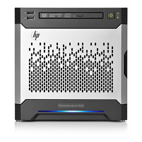
Component identification Front panel components Item Description USB 2.0 connectors Optical drive (optional) Drive bays (inside) Front bezel Component identification 6... -
Page 7: Front Panel Leds And Buttons
Front panel LEDs and buttons Item Description Status Power On/Standby button Solid green = System on and system power LED Flashing green (1 Hz/cycle per sec) = Performing power on sequence Solid amber = System in standby Off = No power present* NIC status LED Solid green = Link to network Flashing green (1 Hz/cycle per sec) = Network active... -
Page 8: Rear Panel Components
Rear panel components Item Description Kensington security slot Power supply Serial number/iLO information tag* Power cord connector Dedicated iLO 4 connector Video connector USB 3.0 connectors USB 2.0 connectors NIC connector 2 NIC connector 1/shared iLO 4 connector System fan * The serial number/iLO information tag shows the server serial number and the default iLO account information. -
Page 9: Rear Panel Leds And Buttons
Rear panel LEDs and buttons Item Description Status NIC link LED Solid green = Link exists Off = No link exists NIC status LED Solid green = Link to network Flashing green (1 Hz/cycle per sec) = Network active Off = No network activity System board components Component identification 9... - Page 10 Item Description Fan connector DIMM slots Front I/O connector Processor socket TPM connector System battery Mini-SAS connector Optical drive SATA connector Ambient temperature sensor connector 24-pin system board power connector Internal USB 2.0 connector microSD card slot NMI header PCIe2 x16 (8, 4, 1) slot System maintenance switch Component identification 10...
-
Page 11: Dimm Slot Locations
DIMM slot locations DIMM slots are numbered 1 and 2. The supported AMP modes use the letter assignments for population guidelines. System maintenance switch Position Default Function Off = iLO 4 security is enabled. On = iLO 4 security is disabled. Off = System configuration can be changed. -
Page 12: Nmi Functionality
To force the system to invoke the NMI handler and generate a crash dump log, do one of the following: • Use the iLO Virtual NMI feature. • Short the NMI header ("System board components" on page 9). For more information, see the HP website (http://www.hp.com/support/NMI). Drive numbering The server supports four LFF non-hot-plug SATA drives. Component identification 12... -
Page 13: Fan Location
Fan location The server has one system fan located at the rear of the server. L-wrench The server includes an L-wrench located on the front panel. The long end is for a Phillips #2 screw head and the short one is for T-15 screw head. Use this L-wrench to loosen screws during hardware configuration procedures. -
Page 14: Operations
Operations Power up the server Connect the power cord to the server. Press the Power On/Standby button. The server exits standby mode and applies full power to the system. The system power LED changes from amber to green. Power down the server Before powering down the server for any upgrade or maintenance procedures, perform a backup of critical server data and programs. -
Page 15: Open The Front Bezel
• Press and hold the Power On/Standby button for more than 4 seconds to force the server to enter standby mode. This method forces the server to enter standby mode without properly exiting applications and the OS. If an application stops responding, you can use this method to force a shutdown. •... -
Page 16: Remove The Front Bezel
Slide the release tab upward to unlock the front bezel from the chassis. Open the front bezel. Remove the front bezel Open the front bezel (on page 15). Operations 16... -
Page 17: Install The Front Bezel
Release the bezel hinges from the front panel. Install the front bezel If the chassis cover was removed, install it ("Install the chassis cover" on page 18). Attach the bezel to the front panel, and then close it. If the chassis cover was removed, do the following: Connect the power cord to the server. -
Page 18: Remove The Chassis Cover
Remove the chassis cover Power down the server (on page 14). Disconnect the power cord from the AC source. Disconnect the power cord from the server. Disconnect all peripheral cables from the server. If a Kensington security cable is installed, disconnect it from the rear panel. See the security cable documentation for instructions. -
Page 19: Remove The System Board Assembly
Connect the Ethernet cable ("Connecting the Ethernet cable" on page 25). Connect the server to the switch ("Setting up the HP networking options" on page 30). Connect the power cord to the server. Power up the server (on page 14). - Page 20 In the following system board illustration, the gray connectors correspond to the system board cables that you must disconnect. Press the system board tray latch. Operations 20...
-
Page 21: Install The System Board Assembly
Slide the system board assembly completely out of the chassis. Install the system board assembly Slide the system board assembly into the chassis. Connect all cables disconnected from the system board and/or expansion board. Operations 21... -
Page 22: Setup
Setup Optional services Delivered by experienced, certified engineers, HP Care Pack services help you keep your servers up and running with support packages tailored specifically for HP ProLiant systems. HP Care Packs let you integrate both hardware and software support into a single package. A number of service level options are available to meet your needs. -
Page 23: Temperature Requirements
Because of the high ground-leakage currents associated with multiple servers connected to the same power source, HP recommends the use of a PDU that is either permanently wired to the building’s branch circuit or includes a nondetachable cord that is wired to an industrial-style plug. NEMA locking-style plugs or those complying with IEC 60309 are considered suitable for this purpose. -
Page 24: Server Warnings And Cautions
CAUTION: When installing hardware or performing maintenance procedures requiring access to internal components, HP recommends that you first back up all server data to avoid loss. Identifying the server box contents Unpack the server shipping carton and locate the materials and documentation necessary for installing the server. -
Page 25: Connecting Peripheral Devices
Microsoft Windows Server 2008 R2 SP1 The USB 3.0 driver is included in the SPP download when performing an Intelligent Provisioning-assisted system setup. For more information about Intelligent Provisioning drivers, firmware, and SPP, see the HP website (http://www.hp.com/go/spp/download). Connecting the Ethernet cable The server supports the following Ethernet connectors located on the rear panel: •... -
Page 26: Powering On And Selecting Boot Options
• Dedicated iLO connector To connect an Ethernet cable: Connect one end of the Ethernet cable to the NIC 1 connector. Connect the other end of the Ethernet cable to a network jack. Powering on and selecting boot options Setup 26... - Page 27 WARNING: To reduce the risk of electric shock or damage to the equipment: • Do not disable the power cord grounding plug. The grounding plug is an important safety feature. Plug the power cord into a grounded (earthed) electrical outlet that is easily accessible at all •...
-
Page 28: Performing The Initial System Setup
Follow the prompts on the Set Preferences screen to activate Intelligent Provisioning. If you intend to register for HP Insight Remote Support, you should have your HP Passport user name and password ready. For more information, see the HP Insight Remote Support and Insight Online Setup Guide for ProLiant Gen8 Servers and HP BladeSystem c-Class Enclosures on the HP website (http://www.hp.com/go/insightremotesupport/docs). - Page 29 On the Maintenance screen, click HP Smart Storage Administrator (HP SSA). The system launches the HP SSA GUI. On the left-hand side of the screen, select the preferred HP Smart Array Controller device, and then click Configure under the available options.
-
Page 30: Registering The Server
Setting up the HP networking options HP PS1810-8G Switch setup If you intend to use the server with the companion HP PS1810-8G Switch, follow the procedures in this section. For more information on switch-related settings and operational procedures, see the HP website (http://www.hp.com/go/ps1810). - Page 31 Attach the self-adhesive rubber pads to the bottom surface of the switch. CAUTION: The switch has a limitation on how much weight can be placed on top of it. To reduce the risk of personal injury or damage to the equipment because of an unstable server-switch stacking, stack no more than two servers on top of the switch.
- Page 32 Connect the power adapter to the AC power source. If you are using an in-line power adapter, do the following: Connect the power adapter to the switch. Connect the power cord to the adapter. Connect the power cord to the AC power source. Check the status of the switch Power LED.
- Page 33 To establish a simple Ethernet connection: Connect an Ethernet cable to the server NIC connector 1 or 2. Connect the cable to any switch LAN port. To establish an Ethernet connection with iLO functionality by using the dedicated iLO connector: Connect an Ethernet cable to the server NIC 1 or NIC 2 connector, and then connect the cable to a switch LAN port.
-
Page 34: Hp Ps110 802.11N Wireless Vpn Router And Hp Ps1810-8G Switch Setup
HP PS110 802.11n Wireless VPN Router and HP PS1810-8G Switch setup The HP PS110 802.11n Wireless VPN Router and the HP PS1810-8G Switch are companion networking options for the HP ProLiant MicroServer Gen8. Follow these instructions to set up the router and switch with the server: Set up the router ("HP PS110 802.11n Wireless VPN Router setup... - Page 35 To achieve maximum wireless coverage, the PS110 must be placed on the very top of the stack of all MicroServer devices. For example, if you are using an HP PS1810-8G Switch on top of the MicroServer, the PS110 router must be placed on top of the switch.
- Page 36 • A simple Ethernet connection with no iLO functionality • An Ethernet connection with iLO functionality, using the dedicated iLO connector • An Ethernet connection with iLO functionality, using the shared iLO connector To connect the server to the router: Connect a standard Ethernet cable from the modem to the router WAN port.
- Page 37 Connect another Ethernet cable to the server dedicated iLO connector, and then connect the cable to a router LAN port. If you prefer to have an Ethernet connection with shared iLO functionality, do the following: Enable the shared iLO functionality of the server ("Enabling the shared iLO functionality on the MicroServer"...
- Page 38 For detailed instructions for this step, see the Quickstart document that shipped with the router. HP PS1810-8G Switch setup procedures For deployments requiring more than four network ports on the router, HP recommends adding the HP PS1810-8G Switch. Mount the switch with the server...
- Page 39 Attach the self-adhesive rubber pads to the bottom surface of the switch. CAUTION: The switch has a limitation on how much weight can be placed on top of it. To reduce the risk of personal injury or damage to the equipment because of an unstable server-switch stacking, stack no more than two servers on top of the switch.
- Page 40 Top stacking—Stack the switch on the top of the server. You can stack up to three MicroServers. Complete the switch Self-Test Connect an Ethernet cable to the switch, and then connect the cable to a network jack. If you are using a wall-mount power adapter, do the following: Connect the power adapter to the switch.
- Page 41 Connect the power adapter to the AC power source. If you are using an in-line power adapter, do the following: Connect the power adapter to the switch. Connect the power cord to the adapter. Connect the power cord to the AC power source. Check the status of the switch Power LED.
-
Page 42: Enabling The Shared Ilo Functionality On The Microserver
Connect the switch to the router The HP recommended setup configuration is for the server to be connected to the switch LAN port only. As such, disconnect the Ethernet cable connecting the router LAN port to the server NIC connector. - Page 43 To close the iLO RBSU, under the File menu, select the Exit option. Setup 43...
-
Page 44: Hardware Options Installation
For more information about product features, specifications, options, configurations, and compatibility, see the product QuickSpecs on the HP website (http://www.hp.com/go/qs). To install the component: Perform steps 1 to 3 only if the front bezel is secured from inside the chassis. - Page 45 Separate the bezel faceplate from the bezel frame. Store the removed bezel faceplate for future use. Install the preferred bezel faceplate to the bezel frame, and then secure the assembly with the screws removed in the previous step. Spare screws are also included in the option kit. Install the front bezel, and then close it.
-
Page 46: Drive Options
Installing a non-hot-plug drive For more information about product features, specifications, options, configurations, and compatibility, see the product QuickSpecs on the HP website (http://www.hp.com/go/qs). CAUTION: To prevent improper cooling and thermal damage, do not operate the server unless all bays are populated with either a component or a blank. - Page 47 To install the component: Power down the server (on page 14). Disconnect the power cord from the AC source. Disconnect the power cord from the server. Open the front bezel (on page 15). Remove the drive carrier. Remove the two metal brackets from the drive carrier. Install the drive in the carrier.
-
Page 48: Controller Options
Controller options The server ships with an embedded Smart Array B120i controller. For more information about the controller and its features, see the HP Dynamic Smart Array RAID Controller User Guide on the HP website (http://www.hp.com/go/smartstorage/docs). To configure arrays, see the HP Smart Storage Administrator User Guide on the HP website (http://www.hp.com/go/smartstorage/docs). -
Page 49: Installing A Storage Controller
The server exits standby mode and applies full power to the system. The system power LED changes from amber to green. For more information about the storage controller and its features, select the relevant controller user documentation on the HP website (http://www.hp.com/go/smartstorage/docs). Hardware options installation 49... -
Page 50: Installing The Fbwc Module And Capacitor Pack
To configure arrays, see the HP Smart Storage Administrator User Guide on the HP website (http://www.hp.com/go/smartstorage/docs). Installing the FBWC module and capacitor pack CAUTION: In systems that use external data storage, be sure that the server is the first unit to be powered down and the last to be powered back up. - Page 51 Route the capacitor pack cable through the internal left side chassis opening down to the system board. Connect the capacitor pack cable to the cache module. Secure the capacitor pack cable in the designated cable management clips: Secure the cable in the two rear side cable clips. Secure the cable in the internal left side chassis cable clip.
-
Page 52: Optical Drive Option
Optical drive option For more information about product features, specifications, options, configurations, and compatibility, see the product QuickSpecs on the HP website (http://www.hp.com/go/qs). To install the component: Power down the server (on page 14). Disconnect the power cord from the AC source. - Page 53 Press the optical drive blank release latches, and then pull the blank out of the drive bay. Retain the blank for future use. Install the optical drive into the bay. Connect the optical drive SATA Y-cable: Connect the common end of the Y-cable to the optical drive. Connect the power end of the Y-cable to the power supply cable labeled P3.
-
Page 54: Memory Options
For cable routing information, see "Optical drive cabling (on page 65)." Secure the optical drive SATA cable in the designated cable management clips: Secure the excess cable in the top chassis cable clip. Secure the cable in the internal left side chassis cable clip. Install the chassis cover (on page 18). -
Page 55: Hp Smartmemory
HP Active Health and manageability software. Certain performance features are unique with HP SmartMemory. The industry supports UDIMM at 2 DIMMs per channel at 1066 MT/s. HP SmartMemory supports 2 DIMMs per channel at 1333 MT/s, or 25% greater bandwidth. -
Page 56: Single-Rank And Dual-Rank Dimms
L = LRDIMM (load reduced) For the latest supported memory information, see the QuickSpecs on the HP website (http://www.hp.com/go/qs). At the website, choose the geographic region, and then locate the product by name or product category. Single-rank and dual-rank DIMMs DIMM configuration requirements are based on these classifications: •... -
Page 57: Installing A Dimm
When installing DIMMs, populate the 1-A DIMM slot first and, then the 2-B slot. • For DIMM spare replacement, install the DIMMs per slot number as instructed by the system software. • Use only HP qualified DIMMs. • The server does not support: RDIMMs Non-ECC UDIMMs •... -
Page 58: Expansion Board Options
The server has one low-profile PCIe2 x16 expansion slot for controller option installation. For more information about product features, specifications, options, configurations, and compatibility, see the product QuickSpecs on the HP website (http://www.hp.com/go/qs). CAUTION: To prevent improper cooling and thermal damage, do not operate the server unless all PCI slots have either an expansion slot cover or an expansion board installed. - Page 59 For added board stability, remove the screw located underneath the slot cover retainer latch, and then use it to secure the expansion board. Verify that any switches or jumpers on the expansion board are set properly. For more information, see the documentation that ships with the option.
-
Page 60: Hp Trusted Platform Module Option
Recovery Mode after BitLocker detects a possible compromise of system integrity. • HP is not liable for blocked data access caused by improper TPM use. For operating instructions, see the encryption technology feature documentation provided by the operating system. - Page 61 Power down the server (on page 14). Disconnect the power cord from the AC source. Disconnect the power cord from the server. Remove the chassis cover (on page 18). Remove the system board assembly (on page 19). CAUTION: Any attempt to remove an installed TPM from the system board breaks or disfigures the TPM security rivet.
-
Page 62: Enabling The Trusted Platform Module
OS application TPM settings. For more information on firmware updates and hardware procedures, see the HP Trusted Platform Module Best Practices White Paper on the HP website (http://www.hp.com/support). -
Page 63: Cabling
For information on cabling peripheral components, refer to the white paper on high-density deployment at the HP website (http://www.hp.com/products/servers/platforms). CAUTION: When routing cables, always be sure that the cables are not in a position where they can be pinched or crimped. -
Page 64: Capacitor Pack Cabling
• Mini-SAS cable connected to controller board Item Description 4-pin power cable (connected to the PSU P2 cable) Mini-SAS cable Capacitor pack cabling Cabling 64... -
Page 65: Optical Drive Cabling
Optical drive cabling Item Description 4-pin power connector (connected to the PSU P3 cable) of the optical drive SATA Y-cable Common end of the optical drive SATA Y-cable SATA connector of the optical drive SATA Y-cable Front I/O assembly cabling Cabling 65... -
Page 66: Ambient Temperature Sensor Cabling
Ambient temperature sensor cabling System fan cabling Cabling 66... -
Page 67: Power Supply Cabling
Power supply cabling Item PSU cable marker Description 4-pin optical drive power cable 4-pin drive power cable 24-pin system board power cable Cabling 67... -
Page 68: Software And Configuration Utilities
QuickSpecs on the HP website (http://www.hp.com/go/qs). HP iLO The iLO 4 subsystem is a standard component of HP ProLiant servers that simplifies initial server setup, server health monitoring, power and thermal optimization, and remote server administration. The iLO 4 subsystem includes an intelligent microprocessor, secure memory, and a dedicated network interface. -
Page 69: Active Health System
Remotely mount high-performance Virtual Media devices to the server. • Securely and remotely control the power state of the managed server. • Implement true Agentless Management with SNMP alerts from HP iLO, regardless of the state of the host server. • Download the Active Health System log. -
Page 70: Integrated Management Log
The data that is collected is managed according to the HP Data Privacy policy. For more information see the HP website (http://www.hp.com/go/privacy). The Active Health System, in conjunction with the system monitoring provided by Agentless Management or SNMP Pass-thru, provides continuous monitoring of hardware and configuration changes, system status, and service alerts for various server components. -
Page 71: Scripting Toolkit For Windows And Linux
BladeSystem c-Class enclosure, you can register a server or enclosure to communicate directly to HP Insight Online without the need to set up an HP Insight Remote Support centralized Hosting Device in your local environment. HP Insight Online will be your primary interface for remote support information. The direct connect configuration is available in iLO 4 1.40 and later, Intelligent Provisioning 1.60 and later, and... -
Page 72: Hp Insight Diagnostics
Intelligent Provisioning is a single-server deployment tool embedded in HP ProLiant Gen8 and later servers that simplifies HP ProLiant server setup, providing a reliable and consistent way to deploy HP ProLiant server configurations: • Intelligent Provisioning assists with the OS installation process by preparing the system for installing "off-the-shelf"... -
Page 73: Hp Service Pack For Proliant
SPP is a comprehensive systems software (drivers and firmware) solution delivered as a single package with major server releases. This solution uses HP SUM as the deployment tool and is tested on all supported HP ProLiant servers including HP ProLiant Gen8 and later servers. -
Page 74: Using Rbsu
Selecting the primary boot controller • Configuring memory options • Language selection For more information on RBSU, see the HP ROM-Based Setup Utility User Guide on the HP RBSU Information Library (http://www.hp.com/go/rbsu/docs). Using RBSU To use RBSU, use the following keys: •... -
Page 75: Boot Options
To change any ORCA default settings and override the auto-configuration process, press the F8 key when prompted. For more information on RBSU, see the HP ROM-Based Setup Utility User Guide on the HP RBSU Information Library (http://www.hp.com/go/rbsu/docs). Boot options Near the end of the boot process, the boot options screen is displayed. This screen is visible for several seconds before the system attempts to boot from a supported boot device. -
Page 76: Utilities And Features
Provides context-sensitive searchable help content • Provides diagnostic and SmartSSD Wear Gauge functionality on the Diagnostics tab ACU is now available as an embedded utility, starting with HP ProLiant Gen8 servers. To access ACU, use one of the following methods: •... -
Page 77: Hp Smart Storage Administrator
Gen8 servers, HP SSA replaces ACU with an enhanced GUI and additional configuration features. HP SSA exists in three interface formats: the HP SSA GUI, the HP SSA CLI, and HP SSA Scripting. Although all formats provide support for configuration tasks, some of the advanced tasks are available in only one format. -
Page 78: Automatic Server Recovery
ASR is a feature that causes the system to restart when a catastrophic operating system error occurs, such as a blue screen, ABEND (does not apply to HP ProLiant DL980 Servers), or panic. A system fail-safe timer, the ASR timer, starts when the System Management driver, also known as the Health Driver, is loaded. When the operating system is functioning properly, the system periodically resets the timer. -
Page 79: Keeping The System Current
HP website (http://www.hp.com/go/spp/download). To locate the drivers for a particular server, go to the HP website (http://www.hp.com/go/hpsc) and click on Drivers, Software & Firmware. Then, enter your product name in the Find an HP product field and click Software and firmware Software and firmware should be updated before using the server for the first time, unless any installed software or components require an older version. -
Page 80: Hp Operating Systems And Virtualization Software Support For Proliant Servers
HP Proactive Care—For customers running business critical environments where downtime is not an option, HP Proactive Care helps to deliver high levels of availability. Key to these service options is the delivery of proactive service management tools to help you avoid the causes of downtime. If a problem arises, then HP offers advanced technical response from critical system support specialists for problem identification and resolution. - Page 81 For more information, refer to the HP website (http://www.hp.com/go/pcn). Software and configuration utilities 81...
-
Page 82: Troubleshooting
• Simplified Chinese (http://www.hp.com/support/ProLiant_TSG_v1_sc) The HP ProLiant Gen8 Troubleshooting Guide, Volume II: Error Messages provides a list of error messages and information to assist with interpreting and resolving error messages on ProLiant servers and server blades. To view the guide, select a language: •... -
Page 83: System Battery Replacement
System battery replacement If the server no longer automatically displays the correct date and time, then replace the battery that provides power to the real-time clock. Under normal use, battery life is 5 to 10 years. WARNING: The computer contains an internal lithium manganese dioxide, a vanadium pentoxide, or an alkaline battery pack. -
Page 84: Regulatory Information
Hewlett-Packard Company, Address: 3000 Hanover Street, Palo Alto, California 94304, U.S. Local representative information (Russian) • HP Russia • HP Belarus • HP Kazakhstan Local representative information (Kazakh) Manufacturing date The manufacturing date is defined by the serial number (HP serial number format for this product): CCSYWWZZZZ Regulatory information 84... -
Page 85: Turkey Rohs Material Content Declaration
38 for the week of September 9. Turkey RoHS material content declaration Ukraine RoHS material content declaration Warranty information HP ProLiant and X86 Servers and Options (http://www.hp.com/support/ProLiantServers-Warranties) HP Enterprise Servers (http://www.hp.com/support/EnterpriseServers-Warranties) HP Storage Products (http://www.hp.com/support/Storage-Warranties) HP Networking Products (http://www.hp.com/support/Networking-Warranties) Regulatory information 85... -
Page 86: Electrostatic Discharge
Electrostatic discharge Preventing electrostatic discharge To prevent damaging the system, be aware of the precautions you need to follow when setting up the system or handling parts. A discharge of static electricity from a finger or other conductor may damage system boards or other static-sensitive devices. -
Page 87: Specifications
Depending on the installed options and/or the regional location where the server was purchased, the server is configured with one of the following power supplies: • HP 150 W Integrated Power Supply (non-hot-plug, non-redundant) ("HP 150 W Integrated Power Supply specifications"... -
Page 88: Hp 150 W Integrated Power Supply Specifications
HP 150 W Integrated Power Supply specifications Specification Value — Input requirements 100 V AC to 240 V AC Rated input voltage 50 Hz to 63 Hz Rated input frequency 3.5 A at 100 V AC Rated input current < 192W at 100 V AC Rated input power <... -
Page 89: Support And Other Resources
Active Health System log (HP ProLiant Gen8 or later products) Download and have available an Active Health System log for 7 days before the failure was detected. For more information, see the HP iLO 4 User Guide or HP Intelligent Provisioning User Guide on the HP website (http://www.hp.com/go/ilo/docs). - Page 90 HP specifies in the materials shipped with a replacement CSR part whether a defective part must be returned to HP. In cases where it is required to return the defective part to HP, you must ship the defective part back to HP within a defined period of time, normally five (5) business days. The defective part must be returned with the associated documentation in the provided shipping material.
- Page 91 HP sono realizzati con numerosi componenti che possono essere riparati direttamente dal cliente (CSR, Customer Self Repair). Se in fase di diagnostica HP (o un centro di servizi o di assistenza HP) identifica il guasto come riparabile mediante un ricambio CSR, HP lo spedirà direttamente al cliente per la sostituzione.
- Page 92 Si, durante la fase de diagnóstico, HP (o los proveedores o socios de servicio de HP) identifica que una reparación puede llevarse a cabo mediante el uso de un componente CSR, HP le enviará dicho componente directamente para que realice su sustitución. Los componentes CSR se clasifican en dos categorías:...
- Page 93 HP se hará cargo de todos los gastos de envío y devolución de componentes y escogerá la empresa de transporte que se utilice para dicho servicio. Para obtener más información acerca del programa de Reparaciones del propio cliente de HP, póngase en contacto con su proveedor de servicios local.
- Page 94 Opcional – Peças cujo reparo feito pelo cliente é opcional. Essas peças também são projetadas para o reparo feito pelo cliente. No entanto, se desejar que a HP as substitua, pode haver ou não a cobrança de taxa adicional, dependendo do tipo de serviço de garantia destinado ao produto.
- Page 95 Support and other resources 95...
- Page 96 Support and other resources 96...
-
Page 97: Acronyms And Abbreviations
Advanced Memory Protection Automatic Server Recovery Canadian Standards Association Customer Self Repair DDR3 double data rate-3 FBWC flash-backed write cache HP SIM HP Systems Insight Manager HP SSA HP Smart Storage Administrator HP SUM HP Smart Update Manager Acronyms and abbreviations 97... - Page 98 International Electrotechnical Commission Integrated Lights-Out Integrated Management Log International Organization for Standardization large form factor Lights-Out Management LRDIMM load reduced dual in-line memory module LV DIMM low-voltage DIMM nonmaskable interrupt NVRAM nonvolatile memory Onboard Administrator PCIe Peripheral Component Interconnect Express power distribution unit POST Power-On Self Test...
- Page 99 Rapid Deployment Pack RoHS Restriction of Hazardous Substances serial attached SCSI SATA serial ATA Secure Digital HP Service Pack for ProLiant solid-state drive TMRA recommended ambient operating temperature Trusted Platform Module UDIMM unregistered dual in-line memory module Acronyms and abbreviations 99...
- Page 100 universal serial bus Virtual Connect Version Control Agent VCRM Version Control Repository Manager xHCI Extensible Host Controller Interface Acronyms and abbreviations 100...
-
Page 101: Documentation Feedback
Documentation feedback HP is committed to providing documentation that meets your needs. To help us improve the documentation, send any errors, suggestions, or comments to Documentation Feedback (mailto:[email protected]). Include the document title and part number, version number, or the URL when submitting your feedback. -
Page 102: Index
6 front bezel 15 components, rear panel 8 front I/O cabling 65 components, system board 9 front panel buttons 7 contacting HP 89 front panel components 6 controller options 48 front panel LEDs 7 crash dump analysis 12 Index 102... - Page 103 HP Insight Remote Support software 70, 80 NMI functionality 12 HP Proactive Care 80 non-hot-plug drives, installing 46 HP Service Pack for ProLiant 68, 72, 73 notification actions 80 HP Smart Storage Administrator (HP SSA) 77 HP Smart Update Manager overview 68, 73...
- Page 104 Smart Update Manager 68, 73 software 79, 80 warnings 24 space and airflow requirements 22 warranty information 85 specifications, environmental 87 website, HP 89 specifications, power supply 87 weight 87 specifications, server 87 SPP 72, 73 standard ECC 56 Index 104...