Table of Contents
Quick Links
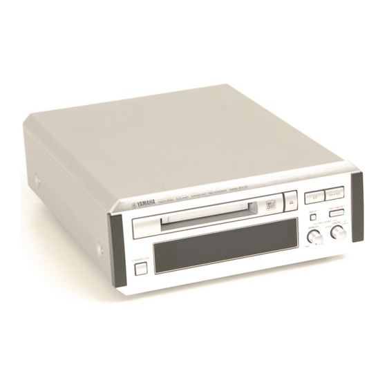
MDX-E100
For the system operation of MDX-E100,
please refer to Service Manual for the
RX-E100 100684 .
This manual has been provided for the use of authorized YAMAHA Retailers and their service personnel.
It has been assumed that basic service procedures inherant to the industry, and more specifically YAMAHA Products, are already
known and understood by the users, and have therefore not been restated.
WARNING:
IMPORTANT:
The data provided is believed to be accurate and applicable to the unit(s) indicated on the cover. The research, engineering, and
service departments of YAMAHA are continually striving to improve YAMAHA products. Modifications are, therefore, inevitable
and specifications are subject to change without notice or obligation to retrofit. Should any discrepancy appear to exist, please contact
the distributor's Service Division.
WARNING:
IMPORTANT:
CONTENTS
TO SERVICE PERSONNEL . . . . . . . . . . . . . . . . . . 1-2
REAR PANELS . . . . . . . . . . . . . . . . . . . . . . . . . . . . . . 2
SPECIFICATIONS . . . . . . . . . . . . . . . . . . . . . . . . . . . . 3
INTERNAL VIEW . . . . . . . . . . . . . . . . . . . . . . . . . . . . . 4
DISASSEMBLY PROCEDURES . . . . . . . . . . . . . . . 4-8
ADJUSTMENT & TEST MODE . . . . . . . . . . . . . . . 9-16
SPECIAL TEST MODE . . . . . . . . . . . . . . . . . . . . . . . 17
ERROR DISPLAY . . . . . . . . . . . . . . . . . . . . . . . . 18-19
TROUBLESHOOTING . . . . . . . . . . . . . . . . . . . . . 20-24
1 0 0 6 8 6
MINIDISC RECORDER
SERVICE MANUAL
IMPORTANT NOTICE
Failure to follow appropriate service and safety procedures when servicing this product may result in personal
injury, destruction of expensive components and failure of the product to perform as specified. For these reasons,
we advise all YAMAHA product owners that all service required should be performed by an authorized
YAMAHA Retailer or the appointed service representative.
The presentation or sale of this manual to any individual or firm does not constitute authorization, certification or
recognition of any applicable technical capabilities, or establish a principle-agent relationship of any form.
Static discharges can destroy expensive components. Discharge any static electricity your body may have accumu-
lated by grounding yourself to the ground buss in the unit (heavy gauge black wires connect to this buss).
Turn the unit OFF during disassembly and parts replacement. Recheck all work before you apply power to the unit.
IC DATA . . . . . . . . . . . . . . . . . . . . . . . . . . . . . . . . 25-34
BLOCK DIAGRAM . . . . . . . . . . . . . . . . . . . . . . . . 35-37
TEST POINT WAVEFORMS . . . . . . . . . . . . . . . . 38-39
PRINTED CIRCUIT BOARD . . . . . . . . . . . . . . . . 40-47
SCHEMATIC DIAGRAM . . . . . . . . . . . . . . . . . . . 48-50
PARTS LIST . . . . . . . . . . . . . . . . . . . . . . . . . . . . . 51-63
GREASE APPLICATION DIAGRAM . . . . . . . . . . . . 64
REMOTE CONTROL TRANSMITTER . . . . . . . . . . . 65
MDX-E100
Chapters
Table of Contents

Related Manuals for Yamaha MDX-E100


Summary of Contents for Yamaha MDX-E100
-
Page 1: Table Of Contents
This manual has been provided for the use of authorized YAMAHA Retailers and their service personnel. It has been assumed that basic service procedures inherant to the industry, and more specifically YAMAHA Products, are already known and understood by the users, and have therefore not been restated. -
Page 2: To Service Personnel
MDX-E100 TO SERVICE PERSONNEL Critical Components Information. AC LEAKAGE Components having special characteristics are marked Z EQUIPMENT WALL TESTER OR OUTLET UNDER TEST EQUIVALENT and must be replaced with parts having specifications equal to those originally installed. INSULATING TABLE CAUTION: USE OF CONTROLS OR ADJUSTMENTS... -
Page 3: Rear Panels
MDX-E100 Danish DETTE MÆRKAT ER ANBRAGT SOM VIST I ILLUSTRATIONEN FOR AT ADVARE BRUGEREN OM AT AP- PARATET INDEHOLDER EN LASERKOMPONENT. DETTE MÆRKAT OM LASEREN ER ANBRAGT PÅ APPARATET SOM EN OPLYSNING OM AT APPARATET INDEHOLDER ET LASERKOMPONENT. ADVARSEL : USYNLIG LASERSTRÅLING VED ÅBNING, NÅR SIKKERHEDSAFBRYDERE ER UDE AF FUNKTION. -
Page 4: Specifications
MDX-E100 SPECIFICATIONS Digital audio system Outputs System LINE OUT (PLAY) MiniDisc digital audio system Type: pin jack Standard output level: 2.0 ± 0.5 Vrms Disc DIGITAL OUT (OPTICAL) MiniDisc Recording method Type: square optical connector jack Magnetic field variation overwrite... -
Page 5: Internal View
MDX-E100 INTERNAL VIEW POWER TRANSFORMER P.C.B. DIGITAL P.C.B. MAIN (1) P.C.B. MAIN (2) MD MECHANISM UNIT CB102 CB107 CB101 DISASSEMBLY PROCEDURES (Remove parts in disassembly order as numbered.) 3. Removal of MD Mechanism Unit 1. Removal of Top Cover a. Remove 4 screws ( q ) and 4 screw ( w ) in Fig. 1. - Page 6 MDX-E100 Disassembly of MD Mechanical Unit Remove the MD mechanical unit according to Steps 1 - 3 of the disassembly procedure (page 4). Removal of MD Main P.C.B. (Fig. 3) 1. Remove 4 screws (Q1). 2. Remove 6 connectors (Q2).
- Page 7 MDX-E100 Removal of Cartridge Holder (Fig.6) 1. Open the roller arm lever in the arrow direction and move the clamper lever to the rear. 2. With a +5V voltage (*2) applied to the red line side of the blue connector of the loading motor, push the rack gear in the arrow direction until the cam plate lever clicks.
- Page 8 MDX-E100 (E1)x1 Removal of Mechanism SW P.C.B. (Fig.7) Ø1.7x3mm • Once the mechanism switch P.C.B. is removed, it will (E1)x1 be necessary to perform “Adjustment of Lead-in Switch Ø1.7x9.5mm Position”. (See page 13.) Mechanism SW P.C.B. 1. Remove 2 screws (E1) and then remove the Mecha- nism SW P.C.B.
- Page 9 MDX-E100 Removal of Spindle Motor (Fig.9) • Once the spindle motor is removed, it will be neces- sary to perform “Pickup Rating”. (See page 14.) 1. Remove 3 screws (C1). 2. Remove the spindle motor by moving it in the arrow direction.
-
Page 10: Adjustment & Test Mode
MDX-E100 ADJUSTMENT & TEST MODE Preparation before Adjustment Test disc Extension cable (see connection diagram on page 14.) Type Test disc Type Part No. High reflecting disc TDYS1 (SONY) [for reproduction] (P/No. TX945850) 1. Extension P.C.B. for servicing TX946230 Low reflecting disc Commercially available mini disc for recording 2. -
Page 11: Auto Pre-Adjustment Mode
MDX-E100 Description of TEST modes 1. AUTO pre-adjustment mode Automatic pre-adjustment is performed. (Grating adjustment mode after this adjustment.) [ _ AUT _ YOBI _ ] Adjusted values are output by using the interface. 2. AUTO adjustment mode Automatic adjustment is performed. -
Page 12: Auto Adjustment Mode
MDX-E100 2. AUTO adjustment mode Step Setting method Remark Display Set the TEST mode to STOP. [ tsm13**e** ] [ EJECT ] No disc is loaded. [ LOADING ] Load a disc. AUTO pre-adjustment menu Press the DISPLAY button AUTO adjustment menu [ _ AUT _ YOBI _ ] (REMOCON) once. -
Page 13: Test
MDX-E100 9. TEST-REC mode Use a disc for confirmation of recording function. (It is used to check the REC function at the specified address.) Step Setting method Remark Display [ _ AUT _ YOBI _ ] Load a disc. AUTO pre-adjustment menu Press the TITLE button (REMOCON) twice. - Page 14 MDX-E100 Lead-in switch position measurement mode Load a TDYS1 disc for reproduction (high reflecting disc). Note) Adjust the position of the lead-in switch to FF85 - FFD2. 1. Loosen 2 screws (A) fixing the mechanism switch P.C.B. 2. Retighten screws while pushing the mechanism switch P.C.B. in the arrow ( ) direction and then measure the position of the lead-in switch again.
- Page 15 MDX-E100 MECHANISM ADJUSTMENT When making adjustment, be sure to connect an extension cable for servicing and an expansion P.C.B. as shown in Fig.15. 1. Optical pickup rating inspection method (Externally attached) Oscilloscope GND (TP1125) IC1101 No.43 pin 100K EOUT (TP1129) IC1101 No.26 pin...
-
Page 16: Press The Set/Enter Button
MDX-E100 PROCEDURE TO WRITE DATA INTO EE-PROM (IC1402) 1. Procedure to change the EE-PROM and write the (5) Press the DISPLAY button (REMOCON) 4 times. Temp initial value of the microprocessor into EE-PROM (1) Replace the EE-PROM. (6) Press the SET/ENTER button (REMOCON). - Page 17 MDX-E100 Slide setting Control setting Item on display Set value Item on display Set value CONTROL1 CONTROL2 SLDLIM SPKLEVm SLDLEV ADJTTM SLKLVk HDEQAD SLKLVt LDEQAD SLKLVm GDEQAD HDEQBC LDEQBC Adjust setting GDEQBC Item on display Set value HALSG LALSG GALSG...
-
Page 18: Special Test Mode
MDX-E100 SPECIAL TEST MODE How to set to the special test mode Press the POWER button while pressing the REC/PAUSE button and the STOP button. Then all the indicators will light up. Operation procedure Every time the REC/PAUSE button is pressed, lighting of indicators and items on the display change as follows. -
Page 19: Error Display
MDX-E100 ERROR DISPLAY Error on display Description Countermeasure Can't REC • Check that the disc is free from scratch, dust, • DEFECT occurred 10 times continuously during REC- PLAY. finger print, black spot, etc. and that • Recordable cluster became “0” due to occurrence of decentering, face deflection, etc. - Page 20 MDX-E100 Error on display Description Countermeasure Can' t Edit • Editing conditions were not satisfied with respect to • Wrong operation procedure was used. Try each editing function. again by using the correct procedure. • Check according to troubleshooting. TMP Over!! •...
-
Page 21: Troubleshooting
MDX-E100 TROUBLESHOOTING When MD fails to operate When the objective lens of the optical pickup becomes dirty, MD may fail to operate. Clean the objective lens first and check MD for reproduction function. If it still fails to operate, check according to the following flow charts. - Page 22 MDX-E100 Disc cannot be loaded properly. Does the loading function work properly when a disc is inserted? Does No.4 pin of CN1901 become “L”? Check CN1901 and SW1956. Does a change occur at either No.1 or 28 pin of IC1601? Check IC1401.
- Page 23 MDX-E100 Normal reproduction Applicable when the E2-PROM value has been confirmed as normal in the test mode Is initialization done properly for reproduction of a high reflecting disc? Does the play time display count up properly? Check IC1201. Is the disc turning properly?
- Page 24 MDX-E100 Recording/reproduction function Load a low reflection disc and after confirming the audio output in the normal reproduction mode, execute recording/reproduction. Does the recording function fail from the starting address? Check that the disc is not in the recording inhibited status.
- Page 25 MDX-E100 Disc motor does not run. Check No.24 and 25 pins of IC1201 as well as soldering Is a correct waveform provided at No.24 and 25 pins of IC1201 and parts of the peripheral circuit. during the focus gain rough adjustment step in the test mode? Is a waveform provided at No.11 and 12 pins of IC1601 as...
-
Page 26: Ic Data
MDX-E100 IC DATA IC1101 : IR3R55 RF Signal Processing ADIPI ADIPO DIFF DIFF ADLPFO ADIP REFI 22KO REFO 22KI BIAS RFADD TCGI TCGO AOUT BOUT EOUT LOGIC FOUT Pin Name Function RF signal input terminal 1 to input RF signal output from pickup... - Page 27 MDX-E100 IC1201 : LR376484 ATRAC Encoder/Decoder 75 74 73 72 71 70 69 68 67 66 65 64 63 62 61 60 59 58 57 56 55 54 53 52 51 EFMO TOTMON PLCK TEMON ACRCER SBCK TCRS RAD0 SBSY...
- Page 28 MDX-E100 IC1201 : LR376484 ATRAC Encoder/Decoder Pin Name Function RAA7 Address output to external D-RAM. ADR7 Address output to external D-RAM. ADR8 RAA8 Data output enable signal output to external D-RAM RAOEX Ground terminal for digital section DGND Column address strobe signal output to external D-RAM RACASX Data input/output with external D-RAM.
- Page 29 MDX-E100 IC1401 : iX0290AW MD System Microprocessor Pin Name Function Input/output port P96 SBCK Input/output port P95 LDVAR (Laser power adjustment output) LDVAR ADJS (for automatic adjustment step check) ADIS SFSY Input/output port P92 LD SW CK input (interrupt input only when used individually)
- Page 30 MDX-E100 IC1401 : iX0290AW MD System Microprocessor Pin Name Function P37/A15 Input/output port P37 Input/output port P36 Input/output port P35 EEPRO EEPRO (E2PROM protect cancel) EPCS EPCS (E2PROM chip selector output) EEPD EEPD (E2PROM serial data output) EEPK EEPK (E2PROM serial clock output) +3.15V...
- Page 31 MDX-E100 IC106 : M30622MA-721FP Main System Microprocessor /CS0 /CS1 /CS2 /CS3 /WRL/WR /WRH/BHE /BCLK /HLDA /HOLD /ALE /RDY/CLK /CTS /RTS /CLK /RXD /TXD /CTS /RTS /CTS /CLKS /CLK /RXD /TXD Port Name Function Data to DEQ P96/ANEX1 P95/ANEX0 XCLK Clock to DEQ...
- Page 32 MDX-E100 IC106 : M30622MA-721FP Main System Microprocessor Port Name Function P63/TxD0 KDATA MD key data P62/RxD0 MDDATA MD data input P61/CLK0 DSCK MD clock output P60//CTS0,/RTS0 MD-ST MD start (MD-ON) P57//RDY,CLKout /MD-RES MD reset output P56/ALE Unused (GND) P55//HOLD /EPM...
- Page 33 MDX-E100 IC703 : YM3436DK DIR (Digital Format Interface Receiver) 24 26 28 25 17 15 14 13 12 31 DAUX HDLT EXTW SYSTEM DOUT CLOCK TSTN TIMING SYNC GENERATOR SYNC CTLP D DIN DATA CLOCK (N.C.) EIAJ (AES/EBU) CONTROLLER DIGITAL AUDIO...
- Page 34 MDX-E100 IC704 : YM6104 DEQ (Digital Equalizer) SERIAL INPUT DATA BUFFER INPUT 8 WORDS PARAMETER CONTROL COEFFICIENT MULTIPLIER MICRO TRANSFER PROGRAM ACCUMULATOR BUFFER RANDOM Q SHIFTER NUMBER Q REGISTER GENERATOR SERIAL OUTPUT 7 WORDS DATA BUFFER OUTPUT 8 WORDS DATA RAM...
- Page 35 MDX-E100 IC705 : YM3437C-FE2 DIT (Digital Audio Interface Signal Transmitter) DOUT MCLK CNTR/BLKIN CLD/AUXEN RSTN CIN/UDB WCIN CCK/CSB MUTE MCLK DM0,DM1 WCIN TIMING GENERATION INPUT DATA FORMAT CONVERSION BI-PHASE DOUT MODULATION CCK/CSB CIN/UDB CONTROL CODE CLD/AUXEN CONVERSION CNTR/BLKIN Pin No.
-
Page 36: Block Diagram
MDX-E100 BLOCK DIAGRAM (MD) - Page 37 MDX-E100 BLOCK DIAGRAM CB102 R.OUT L.OUT R.IN BUFFER BUFFER L.IN LEVEL AVCC Va+6V VR301 /LOADIN 6.5/5V +6.5/5V 6.5/5V IC104 IC102 IC103 (MDM-98A) DSTB MDDATA KDATA ANALOG SEARCH IC101 DECK MD-ST RESET PDOWN Q101 Q103 BACKUP DIGIN Q105 D101,102 DIGOUT IC101...
- Page 38 MDX-E100 TEST POINT WAVEFORM Stopped PLAY PIT PLAY PLAY Stopped NORM: 1k S/s 1997 / 08 / 04 14:19:52 Stopped Stopped NORM: 1M S/s NORM: 100M S/s 1997 / 08 / 04 13:35:24 1997 / 08 / 04 11:23:12 NORM: 100M S/s...
-
Page 39: Test Point Waveforms
MDX-E100 PRINTED CIRCUIT BOARD (Foil side) Note : y ~ o : TEST POINT WAVEFORMS (See page E38/J36) Connect an oscilloscope to the test points (y ~ o) through a filter as shown below. 100K test points oscilloscope MD MAIN PWB-A (BOTTOM VIEW) -
Page 40: Printed Circuit Board
MDX-E100 PRINTED CIRCUIT BOARD (Foil side) P. C. B. MAIN ( 1 ) P. C. B. MAIN ( 1 ) (Surface Mount Device) (Lead Type Device) DGND DIG1 DIG2 /DITRE5 ERRD IN-R /DIRRE5 IN-L LOCKN XCLK R, A, B, G only... - Page 41 MDX-E100 PRINTED CIRCUIT BOARD (Foil side) P. C. B. MAIN ( 3 ) (Lead Type Device) P. C. B. MAIN ( 2 ) (Lead Type Device) FROM : MAIN (1) VIN-R VIN-L Va-6V Va+6V EJECT LOUT PLAY/PAUSE STOP ROUT AAGND...
- Page 42 MDX-E100 PRINTED CIRCUIT BOARD (Foil side) P. C. B. MAIN ( 4 ) P. C. B. MAIN ( 5 ) P.C.B DIGITAL (Lead Type Device) W401 TO : MAIN (1) OUTLET VOLTAGE DITMUTE SELECTOR /DEQRES N.C. DIG3 /CRS XCLK LOCKIN...
-
Page 43: Schematic Diagram
MDX-E100 IC1202 : IX2474AF SCHEMATIC DIAGRAM (MD MAIN) : TEST POINT WAVEFORMS (See page E38/J36) 4M Bit D-RAM MD MAIN PWB-A Write Clock Clock Generator Note : y ~ o Generator TP1215 TP1218 Connect an oscilloscope to the test points (y ~ o) through a... - Page 44 MDX-E100 IC101 ~ 103 : NJM2068MD IC104 : TC74HCT04AF SCHEMATIC DIAGRAM (MAIN) Dual OP-Amp Hex Inverters MUTING –IN – – –IN -5.9 -5.9 –V -5.9 -5.9 P-E48/J46 -6.0 [K-7] IC105 : TC74HC153AF Dual 4 to 1 Data Selectors STROBE DATA INPUTS...
- Page 45 MDX-E100 SCHEMATIC DIAGRAM (DIGITAL) P-E49/J47 [A-3] V301 : 15-BT-53GN PATTERN AREA PIN CONNECTION Note 1) F1, F2 ..Filament 3) NX ....No extend Pin 5) 1G~15G ..Grid 2) NP ....No Pin 4) P1~P35 ..Datum Line GRID ASSIGMENT...
-
Page 46: Parts List
MDX-E100 P ARTS LIST WARNING Components having special characteristics are marked and must be replaced with parts having specifications equal to those originally installed. ELECTRICAL PARTS Carbon resistors (1/6W or 1/4W) are not included in the ELECTRICAL PARTS List. For the part Nos. of the carbon resistors, refer to the last page. - Page 47 MDX-E100 : Note on the Main PCB Of the main PCB part Nos., only the silver (SI) type part Nos. are included in the table. The only different part between the gold (GD) and silver (SI) type parts is the sheet/FL that is attached to the fluorescent character display tube.
- Page 48 MDX-E100 P.C.B. MAIN & DIGITAL Schm Schm Ref. PART NO. Description Ref. PART NO. Description * D106 VU991400 DIODE.ZENR MA8039-L 3.8V Q113 VS883400 TR 2SD2394 E,F D107 VU264200 DIODE 1SR139-400 Q114 VG721700 TR.DGT DTA144ES D108 VU264200 DIODE 1SR139-400 Q115 VE613400 TR...
- Page 49 MDX-E100 P.C.B. DIGITAL Schm Schm Ref. PART NO. Description Ref. PART NO. Description C711 UB052100 C.CE.M.CHP 100pF RD255120 R.CAR.CHP 120Ω 1/10W C712 UB245100 C.CE.M.CHP 0.1uF RD255220 R.CAR.CHP 220Ω 1/10W C713 VJ900700 C.CE.M.CHP 33pF RD255270 R.CAR.CHP 270Ω 1/10W C714 UB245100 C.CE.M.CHP 0.1uF...
- Page 50 MDX-E100 P.C.B. MD MAIN Schm Schm Ref. PART NO. Description Remarks Ref. PART NO. Description Remarks AAX02260 P.C.B. MAIN 92LPWB2976MDSS * C1504 AAX02570 C.CHP 220pF VCCCCY1HH221J * C1100 AAX02530 C.CHP 4.7uF RCKZ0003AWZZ * C1505 AAX02540 C.CHP 100pF VCCCCY1HH101J * C1101 AAX02750 C.CHP...
- Page 51 MDX-E100 P.C.B. MD MAIN Schm Schm Ref. PART NO. Description Remarks Ref. PART NO. Description Remarks * D1300 AAX02470 DIODE SB0209CP VHDSB0209CP1 * R1111 AAX01910 R.CAR.CHP 22KΩ 1/16W VRSCY1JB223J * D1301 AAX02470 DIODE SB0209CP VHDSB0209CP1 * R1112 AAX01910 R.CAR.CHP 22KΩ...
- Page 52 MDX-E100 P.C.B. MD MAIN & OTHER Schm Schm Ref. PART NO. Description Remarks Ref. PART NO. Description Remarks * R1423 AAX01760 R.CAR.CHP 10KΩ 1/16W VRSCY1JB103J * R1706 AAX01790 R.CAR.CHP 1MΩ 1/16W VRSCY1JB105J * R1424 AAX01760 R.CAR.CHP 10KΩ 1/16W VRSCY1JB103J * R1707 AAX01750 R.CAR.CHP...
-
Page 53: Exploded View
MDX-E100 EXPLODED VIEW 200-1 1-21 1-21 1-21 1-20 1-21 1-13 1-15 1-12 1-16 1-17 1-14 1-20 1-13 1-11... - Page 54 MDX-E100 : Note on the Main PCB Of the main PCB part Nos., only the silver (SI) type part Nos. are included in the table. The only different part between the gold (GD) and silver (SI) type parts is the sheet/FL that is attached to the MECHANICAL PARTS fluorescent character display tube.
- Page 55 MDX-E100 EXPLODED VIEW (MD Mechanism Unit) MECHANICAL PARTS (MD Mechanism Unit) Ref. PART NO. Description Remarks Markets V3098100 MD RECORDER UNIT V3098100 AAX02240 MD GUIDE LANGF0033AWZZ AAX02250 MD GUIDE LANGF0034AWZZ AAX02930 DRIVE CHASSIS LCHSM0080AWM1 AAX02270 CARTRIDGE HOLDER LHLDX3004AWM1 AAX02280 CAM PLATE LEVER...
- Page 56 MDX-E100 Ref. PART NO. Description Remarks Markets * 609 AAX01620 WASHER 1.2x3x0.2 LXWZ9269AFZZ * 610 AAX02990 SCREW M1.7x2.1 LXBZ0036AWZZ * 611 AAX01270 SCREW M1.7x8.9 LXBZ0852AFFD * 612 AAX01290 SCREW M2x4 XBPSD20P04K00 * 613 AAX01300 SCREW M1.7x3 XSPSN17P03K00 * CNW2002 AAX02110 MD FLAT CABLE...
-
Page 57: Grease Application Diagram
MDX-E100 GREASE APPLICATION DIAGRAM Grease : Molykote PG664 GB : Molykote BR2PLUS OL : HYDRO-FLUTE EP-68... -
Page 58: Remote Control Transmitter
MDX-E100 REMOTE CONTROL TRANSMITTER SCHEMATIC DIAGRAM 3.64MHz SID303C-01 P2.0/ 1.5V x 2 TEST 10µF 0.1µF PO.0 P2.1 PO.1 P2.2 PO.2 P2.3 PO.3 P2.4 P1.0 P3.0 P1.1 P3.1 R3.3 P3.2 CODE (HEX) FUNCTION CUSTOM DATA CUSTOM 5 (MNO) +100 1 (ABC) - Page 59 MDX-E100 Parts List for Carbon Resistors 1/4W Type Part No. 1/6W Type Part No. 1/6W Type Part No. Value Value 1/4W Type Part No. 1.0 Ω 3100 3100 10 kΩ 7100 7100 HJ35 HF85 HF45 HF45 1.8 Ω 3180 7110 11 kΩ...