Honeywell Wi-Fi VisionPRO 8000 Installation Manual
Hide thumbs
Also See for Wi-Fi VisionPRO 8000:
- User manual (156 pages) ,
- Product data (92 pages) ,
- Owner's manual (41 pages)
Table of Contents
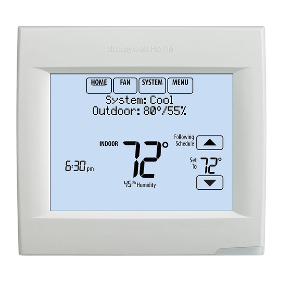
Reference to key features
* Password is the date code.
Wi-Fi VisionPRO
Installation Guide
Current display. Underlined label
signifies the current display.
Mode control buttons. Use to change
settings for Fan or System Heat/Cool.
Menu. Select options to: set schedules,
view equipment status, change IAQ
settings, access installer options*, etc.
Current status. Shows system mode
(heat/cool), outdoor temperature and
humidity.
Current schedule. Shows desired
temperature and schedule status.
Indoor conditions. Shows indoor
temperature and humidity.
Current Time.
message is active or system is set to
Em Heat.
8000
®
Alert Light. On when alert
Table of Contents

Related Manuals for Honeywell Wi-Fi VisionPRO 8000


Summary of Contents for Honeywell Wi-Fi VisionPRO 8000
-
Page 1: Installation Guide
Wi-Fi VisionPRO 8000 ® Installation Guide Reference to key features Current display. Underlined label signifies the current display. Mode control buttons. Use to change settings for Fan or System Heat/Cool. Menu. Select options to: set schedules, view equipment status, change IAQ settings, access installer options*, etc. -
Page 2: Getting Started
Wi-Fi network. RoHs Compliant NOTE: For the product data sheet, please go to Conformité RoHs Assembled in Mexico Assemblé au Mexique forwardthinking.honeywell.com M35344 Password RoHs Compliant Conformité RoHs Assembled in Mexico (Date Code) Assemblé au Mexique... - Page 3 Mount wallplate as shown. Mount new wallplate using screws and anchors included with the thermostat. Drill 3/16-in holes for drywall. Drill 7/32-in holes for plaster. Wallplate Connect power. CONVENTIONAL 24VAC power is required. Connect common side of transformer to C terminal.
-
Page 4: Terminal Designations
Terminal Designations Conventional System Heat Pump Terminal Description Terminal Description Common wire from secondary side of Common wire from secondary side of cooling transformer (if 2 transformers). cooling transformer. Cooling power. Cooling power. Heating power. Heating power. Heat Stage 1 Changeover valve for heat pumps. - Page 5 Performing installer setup Setup options define the type of system you are installing and preferences for the display. Follow prompts on the screen to select the appropriate options. Among the screens you might see will be options for: 1.1 Application, either Residential or APPLICATION Commercial.
- Page 6 Wiring Wiring guide—conventional systems 1H/1C System (2 transformers) 1H/1C System (1 transformer) Power (cooling transformer) [1, 2] Power Power (heating transformer) [1, 2] [R+Rc joined by jumper] Heat relay Heat relay Compressor contactor Compressor contactor Fan relay Fan relay 24VAC common 24VAC common Optional outdoor/remote sensor Optional outdoor/remote sensor...
- Page 7 Wiring Wiring guide—heat pump systems 1H/1C Heat Pump (no auxiliary heat) 2H/2C Heat Pump (no auxiliary heat) Compressor 2 relay Power Power [R+Rc joined by jumper] [R+Rc joined by jumper] Changeover valve Changeover valve Compressor relay Compressor 1 relay Fan relay Fan relay 24VAC common 24VAC common...
- Page 8 Connecting to Wi-Fi After installer setup, you will be prompted to connect to a Wi-Fi network. If you select No, the homeowner NOTE: can connect to the Wi-Fi network later. (See Connect to a “Connecting to Wi-Fi later” on page 10 Wi-Fi network now? or in the User’s Guide.) The thermostat will display its Home screen and thermostat...
- Page 9 The homeowner must have a Total Connect Comfort account. 2.1 Have the homeowner go to mytotalconnectcomfort.com and follow Register at: the instructions to login or create an Honeywell.com/TCC account. 2.2 Press the button to display MAC M35361A and CRC. 2.3 Note the Thermostat MAC and CRC; they will be needed during registration.
- Page 10 Making changes to Installer Setup and performing an Installer Test 1 Touch Menu. Installer Options Installer Options. 2 Select MCR33976 3 Enter password (date code) and Enter password touch Done. See “Finding the password” on 0 0 0 page 9 to find the date code. MCR33977 Installer Setup Installer...
- Page 11 Unsuccessful connection If you are unsuccessful in connecting the thermostat to the Wi-Fi network, you will see a Connection Failed screen. Press the button for other tips about this failed connection. Here are three specific reasons the connection might be unsuccessful. Done For all Connection Failed screens, pressing will return to the Menu screen.
- Page 12 Connecting to a hidden Wi-Fi network If the Wi-Fi network name is hidden and it doesn’t show up in the list in “Connecting to Wi-Fi” follow these steps to connect to it. 1 Press MENU, then Wi-Fi Setup. DoaIol Inrol Madorl Wi-Fi Setup Installer Options M35352...
-
Page 13: Electrical Ratings
Specifications and replacement parts Operating Ambient Temperature Thermostat: 32 to 120° F (0 to 48.9° C) Operating Relative Humidity Thermostat: 5% to 90% (non-condensing) Physical Dimensions (height, width, depth) Thermostat: 4-15/16 x 4-5/8 x 1-1/8 inches (126 mm x 118 mm x 29 mm) Wi-Fi Communication Supports 802.11 B/G/N home wireless router Frequency: 2.4 Ghz... - Page 16 For assistance please visit http://customer.honeywell.com 1-855-733-5465 or call toll-free: Automation and Control Systems Honeywell International Inc. 1985 Douglas Drive North Golden Valley, MN 55422 http://customer.honeywell.com ® U.S. Registered Trademark. © 2015 Honeywell International Inc. 33-00065—03 M.S. Rev. 10-15 33-00065-03 Printed in U.S.A.