beautypg.com
Manuals
Brands
Honeywell Manuals
Measuring Instruments
Chadwick-Helmuth 8500C
Honeywell Chadwick-Helmuth 8500C Manuals
Manuals and User Guides for Honeywell Chadwick-Helmuth 8500C. We have
1
Honeywell Chadwick-Helmuth 8500C manual available for free PDF download: Maintenance Manual
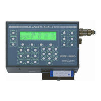
Honeywell Chadwick-Helmuth 8500C Maintenance Manual (186 pages)
Balancer/Analyzer System
Brand:
Honeywell
| Category:
Measuring Instruments
| Size: 2.71 MB
Table of Contents
Table of Contents
5
List of Figures
9
Chapter 1. Introduction
13
About this Manual
13
Purpose and Function
13
System Purpose and Function
13
System Physical Description
14
8500C/C+ Balancer/Analyzer (Figure 1-1)
14
Balancer/Analyzer Assembly
14
Printer/Disk Drive Assembly
14
Figure 1-1. 8500C/C+ Balance/Analyzer
15
Figure 1-2. 8520C Signal Selector
16
Figure 1-3. System Cables
17
Figure 1-4. System Accessories (Not to Scale)
18
8520C Signal Selector (Figure 1-2)
19
Leading Particulars
19
Related Publications
19
Table 1-1. 8500C/C+ Balancer/Analyzer System, Major Components
19
Table 1-2. System Interconnect Cables
20
Table 1-4. Leading Particulars
22
Table 1-5. Related Publications
24
Chapter 2. 8500C/C+ Handling and Installation
25
Preparation for Use
25
Cable Interconnections
25
Unpacking
25
Disk Installation (Figure 2-1)
26
Figure 2-1. Inserting Disk in Disk Drive
26
Printer Paper Loading (Figure 2-3)
26
Printer Paper Removal (Figure 2-2)
26
Figure 2-2. Removing Printer Paper
27
Figure 2-3. Loading Printer Paper
27
Repacking
28
Storage
28
Chapter 3. 8500C/C+ Operation
29
Softkey Functions (Figure 3-1)
29
8500C/C+ Cold-Start Procedure
29
8500C/C+ Warm-Start Procedure
29
Figure 3-1. 8500C Controls and Indicators
30
Figure 4-1. 8500C/C+ Balancer/Analyzer System Block Diagram
31
Chapter 4. System Theory of Operation
32
Detailed Description
32
8500C/C
32
Balancer/Analyzer Assembly
32
Figure 4-2. Analog Board Block Diagram
34
Figure 4-3. Digital Board Block Diagram
37
Figure 4-4. Heater/El Control Board
38
Printer/Disk Drive Assembly
39
8520C Signal Selector
40
Controller Board (Figure 4-6)
40
Figure 4-5. Power Supply Board Block Diagram
40
Figure 4-6. Controller Board and Quad Peak Detector Board Block Diagram
41
Velocimeter BIT (Figure 4-6)
42
Power Supply Board (Figure 4-7)
42
Figure 4-7. Power Supply Board Block Diagram (8520C)
43
Quad Peak Detector Board
43
Maintenance and Repair
45
Table 5-1. Test Equipment
45
Chapter 5. Maintenance and Repair
46
Figure 5-1. Test Cable Fabrication Information
46
Maintenance and Repair
46
Routine Maintenance Procedures
47
Periodic Inspection Procedures
47
Functional Tests
47
8500C/C+ Balancer/Analyzer System Test Procedure (with 8520C)
47
Section 5.2 Routine Maintenance Procedures
47
Section 5.3 Periodic Inspection Procedures
47
Section 5.4 Functional Tests
47
Table 5-2. Routine Maintenance Procedures
47
Test Setup
47
Balance Test
48
Figure 5-2. Functional Test Setup (with Magnetic Pickup)
48
Power-Up Self-Test
48
Figure 5-3. Typical Balance Test Displays for 900 RPM
49
Figure 5-4. Typical Balance Test Displays for 1800 RPM
50
Spectrum Test
52
Table 5-3. Velocimeter and Magnetic Pickup Balance Test Channel Combinations
52
Figure 5-5. Typical Spectrum Test Displays
53
Track Test
53
Fastrak
54
Figure 5-6. Functional Test Setup (with Tracker)
55
Figure 5-7. Special Overlay
55
Disk Drive Test Procedure
56
Calibration Tests
56
8500C/C+ Balancer/Analyzer Test Procedure
56
Section 5.5 Calibration Tests
56
Test Setup
56
Amplitude, Frequency, and Phase Accuracy Tests
57
Power-Up Self-Test
57
Figure 5-8. 8500C/C+ Calibration Test Setup
58
Anti-Alias Filter Response
59
Noise and Spurious Signals Test
59
8520C Signal Selector Test Procedure
61
Amplitude, Frequency, and Phase Accuracy Test
61
Figure 5-9. 8520C Calibration Test Setup
61
Power-Up Self-Test
61
Test Setup
61
Table 5-4. 8520C Velocimeter and Magnetic Pickup Amplitude, Frequency, and Phase
63
Channel Crosstalk Test
64
Table 5-5. Suggested 8520C Velocimeter Channel Crosstalk Combinations
64
8500C/C+ Spectrum Accuracy Test (with 8520C)
65
Power-Up Self-Test
65
Test Procedure: High Frequency Range
65
Test Setup
65
Figure 5-10. Spectrum Accuracy Test Setup
67
Table 5-6. Spectrum Accuracy, High Frequency Range
69
Test Procedure: Low Frequency Range
69
Table 5-7. Specification: Spectrum Accuracy, Low Frequency Range
72
Figure 5-11. Troubleshooting Only: Spectrum Accuracy Test Setup W/O 8520C
73
Troubleshooting Guide
74
Section 5.6 Troubleshooting Guide
74
Table 5-8. Troubleshooting Guide
75
Table 5-9. 8500C/C+ Balancer/Analyzer Functional Tests
81
Table 5-10. 8500C/C+ Balancer/Analyzer Calibration Tests
83
Table 5-11. 8520C Signal Selector Tests
85
Figure 5-12. Troubleshooting Flowchart: 8500 Pilot Light
86
Figure 5-13. Troubleshooting Flowchart: 8520C Power Light
87
Repair
88
Cleaning
88
Section 5.7 Repair
88
Surfaces and Cables
88
Table 5-12. Minor Repair Procedures
88
Disk Drive Cleaning Procedure
89
Figure 5-14. Cable Schematics
90
Inspection
91
Table 5-13. Inspection
91
EPROM Change Procedure (Figure 5-15)
92
Figure 5-15. EPROM Locations on Digital Board
92
Preparation
92
Procedure
92
Battery Pack Check
93
Battery Pack Check and Replacement
93
Battery Pack Replacement (Figure 5-17)
93
8500C Heater/El Board (A4) Fuse (Figure 5-17)
94
8500C Power Supply Board (A3) Fuse (Figure 5-18)
94
8520C Power Supply Board (A2) Fuse (Figure 5-20)
94
Fuse Replacement
94
8500C/C+ Disassembly
95
Disassembly
95
Disassembly of Balancer/Analyzer Assembly (Figure 5-17)
95
Figure 5-16. Opening 8500C/C+ Unit to Access Balancer/Analyzer Assembly
95
Section 5.8 Disassembly
95
Table 5-14. Tools for Disassembly/Reassembly
95
Disassembly of Printer/Disk Drive Assembly (Figure 5-18)
96
Figure 5-17. Balancer/Analyzer Assembly Parts Breakdown
97
Figure 5-18. Printer/Disk Drive Assembly Parts Breakdown
99
Controller Board A1
100
Quad Peak Detector Board A3
100
Signal Selector 8520C Disassembly (Figure 5-20)
100
Harness Assemblies (Figure 5-21)
101
Power Supply Board A2
101
Figure 5-19. 8500C/C+ Harness Assembly
103
Figure 5-20. Signal Selector 8520C Parts Breakdown
107
Figure 5-21. 8520C Harness Assemblies
109
8500C/C+ Reassembly
113
Controller Board A1
113
Power Supply Board A2
113
Quad Peak Detector A3
113
Reassembly
113
Reassembly of Printer/Disk Drive Assembly
113
Section 5.9 Reassembly
113
Signal Selector 8520C Reassembly (Figure 5-13)
113
Reassembly of Balancer/Analyzer Assembly (Figure 5-17)
114
List of Field-Replaceable Components
116
Section 5.10 List of Field-Replaceable Components
116
Table 5-15. 8500C/C+ Balancer/Analyzer
118
Table 5-16. 8520C Signal Selector
119
Cage Codes
121
Section 5.11 Cage Codes
121
Appendix A. 8520C-36 Signal Selector
123
Introduction
123
Physical Description (Figure
123
Theory of Operation
123
Figure A-1. 8520C-36 Controller Board and Mux Board Block Diagram
124
Test Equipment
124
A.4 Maintenance
124
Figure A-2. Initial 8520C-36 Test Setup (W/C-130 Nacelle Harness
125
Figure A-3. 8520C-36 Test Setup W/Velos
129
Figure A-4. 8520C-36 Test Setup W/Velos (Single Channel
132
Figure A-5. 8520C-36 Test Setup W/P-3 Nacelle Harness Assemble
134
Figure A-6. 8520C-26 Test Setup W/Velos
137
Figure A-7. 8500C/C+/8520C-36 Spectrum Accuracy Test Setup
142
Figure A-8. 8520C-36 Test Cable Schematic
143
Figure A-9. 8520C-36 Channel Pin-Outs
144
Figure A-10. 8520C-36 Signal Selector Parts Breakdown
147
Figure A-11. 8520C-36 Signal Selector Wiring Diagram
148
Figure A-12. C-130 Nacelle Harness P/N 11690 Wiring Diagram
149
Figure A-13. P-3 Nacelle Harness P/N 14440 Wiring Diagram
150
Figure A-14. Cable P/N 11517 Schematic
151
8520C-36 List of Field-Replaceable Components
152
Table A-1. 8520C-36 Signal Selector
152
Appendix B. 8500C Heater Modification
155
Figure C-1. Velocimeter and Magnetic Pickup Signal Phase Relationships
157
Appendix C. Chadwick-Helmuth Phase Measurement Convention
158
Appendix D. 8520CS Signal Selector
159
Introduction
159
Leading Particulars
159
Table D-1. 8520CS Signal Selector (Only
159
Physical Description (Figure
160
Theory of Operation
160
Functional Tests
161
Figure D-1. Signal Conditioner Board
161
Figure D-2. Functional Test Setup (with Magnetic Pickup
162
Figure D-3. Typical Balance Test Display
163
Table D-2. Velocimeter and Magnetic Pickup Balance Test Channel Combinations
164
Figure D-4. Functional Test Setup (with High Temp Accelerometer and Photocell
166
Table D-3. Accelerometer and Photocell Balance Test Channel Combinations
168
Calibration - Charge Converter Amplifiers
170
Figure D-6. Special Overlay
170
Figure D-7. Charge Converter Test Fixture
170
Figure D-8. Functional Test Setup Charge Converter Amplifier Calibration
172
Table D-4. Charge Amplifier Adjustments
172
Figure D-9. Charge Converter Adjustments on PC Board
173
Figure D-10. Charge Amplifier DIP Switch Setting
173
Figure D-11. 8520CS Signal Selector Illustrated Parts Breakdown
176
Table D-5. Bill of Material for 8520CS
177
Figure D-12. Wiring Diagram 8520CS
179
Related Products
Honeywell AUTOCUBE 8200
Honeywell Chadwick-Helmuth 8500C+
Honeywell 854 ATG Series
Honeywell 8LS3
Honeywell 8832001S
Honeywell MILLER ManHandler 8442SS-Z7/65FT
Honeywell MILLER ManHandler 8442-Z7/100FT
Honeywell 8327A
Honeywell 802385
Honeywell Experion 8U-TCNTA1
Honeywell Categories
Thermostat
Controller
Control Unit
Security Camera
Accessories
More Honeywell Manuals