Bosch B450 Installation & Operation Manual
Conettix plug-in communicator interface
Hide thumbs
Also See for B450:
- Installation and operation manual (49 pages) ,
- Installation manual (49 pages)
Table of Contents
Quick Links
- 1 Bus Address Settings
- 2 Setting the Bus Address
- 3 Insert the B44X Communication Module (Required and Available Separately)
- 4 Installation
- 5 Wire to an Sdi2 Control Panel
- 6 Configuration for Sdi2 Control Panels
- 7 Use Usb to Configure the B450
- 8 Led Status Indicators
See also:
Operation & Installation Manual
Table of Contents

Related Manuals for Bosch B450


Summary of Contents for Bosch B450
- Page 1 Conettix Plug-in Communicator Interface B450 Installation and Operation Guide...
-
Page 3: Table Of Contents
Conettix Plug-in Communicator Table of Contents | en Interface Table of contents Safety Introduction About documentation Bosch Security Systems, Inc. product manufacturing dates Installation workflow System overview Module overview Bus address settings Installation Setting the bus address Insert the B44x communication module (required and available separately) Mount the module in the enclosure 4.3.1... -
Page 4: Safety
Safety ESD Precaution Please note that while the B450 comes in a plastic case, and is protected from ESD, the plug- in cellular communicator (B44x) does not. All plug-in cellular communicator components may potentially be exposed to finger touches - therefore extra attention must be paid to ESD (electrostatic discharge) precaution. -
Page 5: Introduction
(required and available separately), page 10) Mount the B450 into the enclosure (Refer to Mount the module in the enclosure, page 11) Wire the B450 to a compatible control panel (Refer to Wire to the control panel, page 13) Power up the system Bosch Security Systems, Inc. - Page 6 Review signal strength on the cellular communicator. Refer to your cellular communicator Installation Guide for more information on signal strength. Installation is complete See also – Configuration, page 17 – Maintenance and troubleshooting, page 39 2013.09 | 02 | F.01U.282.875 Installation and Operation Guide Bosch Security Systems, Inc.
-
Page 7: System Overview
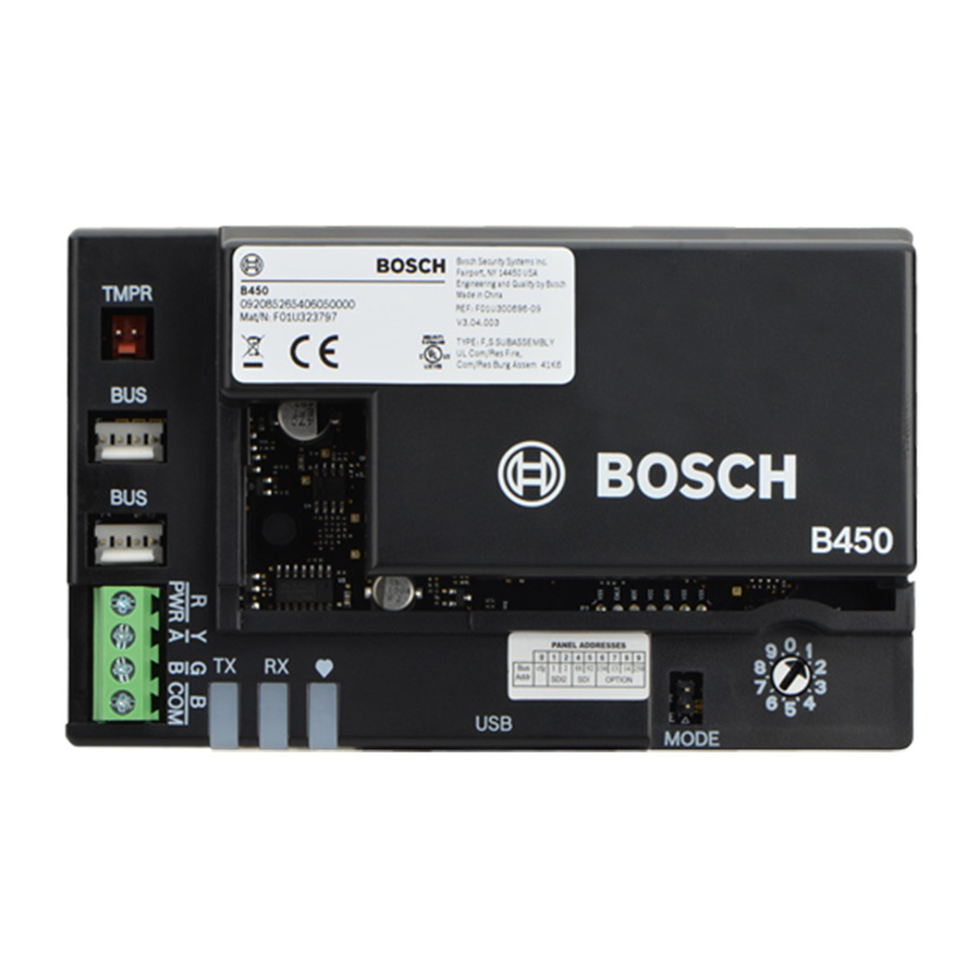
5 ᅳ B44x Plug-in Cellular Communicator (required and available separately) Module overview The B450 Conettix Plug-in Communicator Interface (wired to a compatible control panel) is a four-wire powered SDI2, or SDI device that provides two-way communication over commercial cellular networks using a plug-in communicator. -
Page 8: Bus Address Settings
Notice! The B450 reads the bus address switch setting only during power up. If you change the switch after you apply power to the module, you must cycle the power to the module in order for the new bus address setting to be used for bus communication. - Page 9 Use the bus address label to select the desired setting on the bus address switch, depending on your control panel. PANEL ADDRESSES Addr SDI2 Option TX RX Figure 3.2: Bus address label Bosch Security Systems, Inc. Installation and Operation Guide 2013.09 | 02 | F.01U.282.875...
-
Page 10: Installation
Table 4.1: B450 address switch settings Insert the B44x communication module (required and available separately) Insert the desired B44x communication module into the slot of the B450 until you feel the module “click” into place. 2013.09 | 02 | F.01U.282.875 Installation and Operation Guide Bosch Security Systems, Inc. -
Page 11: Mount The Module In The Enclosure
Notice! If you are not using the interconnect cable, it is recommended to wire the B450 module to the compatible control panel via the terminal strip prior to mounting the B450 into the enclosure. Failure to do so will complicate the mounting procedure. -
Page 12: Mount And Wire The Tamper Switch (Option For Sdi2 Bus Only)
The control panel powers the B450 via the terminal block or bus connection. Installing in a separate enclosure Install the B450 on the inside wall of a separate enclosure. The control panel in a nearby, separate enclosure powers the B450 via the terminal block or bus connection. -
Page 13: Wire To The Control Panel
2 ᅳB44x plug-in cellular communicator antenna cable (connected to the module) Wire to the control panel When you wire a B450 to an SDI, or SDI2 control panel, you can use either the module's terminal strip labeled R, Y, G, B (PWR, A, B, COM) or the module's interconnect wiring connectors (wire included). -
Page 14: Wire To An Sdi2 Control Panel
Figure 4.5: Using terminal strip or interconnect cable wiring on an SDI2 control panel (B Series control panel shown) Callout ᅳ Description 1 ᅳ Compatible SDI2 control panel (B Series control panel shown) 2 ᅳ B450 3 ᅳ Terminal strip wiring 4 ᅳ Interconnect cable 2013.09 | 02 | F.01U.282.875... -
Page 15: Wire To An Sdi Control Panel
Figure 4.6: Using terminal strip or interconnect cable wiring on an SDI control panel (GV3 Series control panel shown) Callout ᅳ Description 1 ᅳ Compatible SDI control panel (GV3 Series control panel shown) 2 ᅳ B450 3 ᅳTerminal strip wiring 4 ᅳ Interconnect cable Bosch Security Systems, Inc. -
Page 16: Wire To An Option Bus Control Panel
Notice! When wiring the connections between the option bus terminal strip and the B450, verify the terminal position of the colored wires as they may be in a different orientation (option bus = R, B, G, and Y) and (B450 = R, Y, G, and B). -
Page 17: Configuration
Configuration Notice! Power up the system prior to the configuration workflows described in this chapter. You can configure the B450 using one of the methods described in this section for your control panel type. Plug and Play configuration When installing under the following conditions, the B450 needs no further configuration: –... - Page 18 Conettix Plug-in Communicator en | Configuration Interface Figure 5.1: B450 settings shown as B42x in RPS with a GV4 control panel at v1.00 2013.09 | 02 | F.01U.282.875 Installation and Operation Guide Bosch Security Systems, Inc.
- Page 19 Conettix Plug-in Communicator Configuration | en Interface Figure 5.2: B450 settings shown as B42x in RPS with a GV4 control panel at v2.00 Reference the table below for parameters configured by RPS. Bosch Security Systems, Inc. Installation and Operation Guide...
- Page 20 SDI2 control panel. Notice! Only control panels with a SDI2 bus connection to the B450 can report a tamper condition. IPv4 DNS Server IP Address IPv4 address format (0.0.0.0) The B450 uses the DNS...
- Page 21 RPS. If you are using a GV4 v2.00 control panel or higher, or a B Series control panel, select ”B426 Ethernet Communicator” within RPS. Information about the B450 such as it's Status, IP Address, Bus Voltage and the assigned phone number of the plug-in module can be found on the RPS Diagnostics screen for the B42X module per figure 5.2.
-
Page 22: Use Usb To Configure The B450
Use USB to configure the B450 You can use a USB connection from a laptop PC to the B450 to configure the B450 on-site. The supported USB cable used to establish connection is a Type A to A, male-to-male cable. - Page 23 USB driver file, and the RBUS1CP.inf file. 11. Supply power to the B450. 12. Connect the B450 to the target PC or laptop, using a USB Type A to A cable. A New Hardware Found window appears on the computer.
-
Page 24: Install A Communication Program
| Configuration Interface 5.3.1 Install a communication program To use USB connection from a computer to the B450 to configure the B450, you must use a communication program. – Windows XP. The Microsoft Windows XP installation automatically installs HyperTerminal, a Microsoft communication program, when Windows installs. -
Page 25: Log Into The Usb Interface
Set up a connection on the new virtual serial COM port (for example, Port: COM7: B450 [COM7]). If the B450 is not connected to the computer, or the USB driver is not installed, the B450 does not appear in the list. - Page 26 The user interface allows three attempts to enter the password correctly. After three failed attempts, the B450 shows a Too many attempts error message, and the USB interface enters into an idle state for 30 sec. Repeat Steps 3 through 6. at the conclusion of 30 sec.
-
Page 27: Usb Main Menu
[Enter] without first selecting an option from the main screen – upon returning from a sub-menu. 5.3.4 USB menu structure The following illustration depicts the B450 menu structure. Bosch Security Systems, Inc. Installation and Operation Guide 2013.09 | 02 | F.01U.282.875... -
Page 28: Usb Menu
Save and Exit Exit * The Diagnostic Log option is used in troubleshooting communication issues with the B450. Use of the Diagnostic Log option is to be used only at the direction of TECHNICAL SUPPORT. Figure 5.10: USB menu structure... - Page 29 Select this option to update the firmware in the B450. Update Notice! Download your update file from the Bosch website prior to performing an update. For more information on Firmware update workflows, refer to Firmware Update page, page 35. 8. Save and Exit Press 8 to save changes and exit the menu.
- Page 30 When signal strength is selected, up to 192 values are displayed representing the signal strength values over the last 48 hours. If the B450 has been powered up less than 48 hours, the list shows only the samples taken so far.
- Page 31 The Re-print all option prints any diagnostic messages that have already occurred and Console Message are stored in the B450’s buffer. This can print what just happened if an issue occurs. 3. Enable Live Enable live console messages provides real time output of diagnostic messages. This...
-
Page 32: Short Message Service (Sms) Configuration
Short Message Service (SMS) configuration The B450 supports configuration by SMS connection. The Short Message Service feature allows an installer to configure the B450 through the use of a mobile phone, or any other service that sends compatible SMS text messages. - Page 33 IDs, refer to the SMS configuration parameters. Notice! Separate each ID or value pair with a semi-colon ; (for example, %1;1=B450;19=1;!). To allow spanning of configuration across multiple messages, each SMS starts with the sequence number followed by the command line separator.
- Page 34 Sample AES key 111213141516; As you enter in the various ID’s into your cell phone, do not press the return key. Doing so will cause the B450 to ignore the programming request. Table 5.7: Double SMS example, part 1 Description...
-
Page 35: Firmware Update Page
Send the Configuration SMS Send the configuration SMS to the B44x module’s phone number. The transmission might take several minutes. Because the bus address switch is set to 0, the B450 waits for an SMS until a message is received. - Page 36 Conettix Plug-in Communicator en | Configuration Interface Figure 5.11: B450 USB login window Select option 7 Firmware Update and press [Enter]. From the Tera Term main menu, select File>Transfer>XMODEM>Send. Figure 5.12: Firmware update send window In the XMODEM Send dialog window, navigate to the folder location and select the firmware update software you downloaded.
- Page 37 Configuration | en Interface Figure 5.13: File navigation Click Open to start the firmware update. The Tera Term: XMODEM Send dialog box opens and indicates the update process. Bosch Security Systems, Inc. Installation and Operation Guide 2013.09 | 02 | F.01U.282.875...
- Page 38 Close the Tera Term session, and re-launch Tera Term. 10. Log back into Tera Term as described previously to re-establish communication from your laptop, to the B450. Communication between the control panel and B450 is restored. 2013.09 | 02 | F.01U.282.875 Installation and Operation Guide...
-
Page 39: Maintenance And Troubleshooting
Conettix Plug-in Communicator Maintenance and troubleshooting | en Interface Maintenance and troubleshooting LED status indicators The B450 includes the following on-board LEDs to assist with troubleshooting: – Heartbeat (system status). – RX (receive). – TX (transmit). The plug-in module also includes LEDs for troubleshooting and status. - Page 40 Switch position On Steady Blink 6 1 Hz Heartbeat trouble Configuration On Steady Blink 7 On Steady failure Table 6.3: B450 module related trouble conditions Condition B450 Heartbeat B450 Transmit B450 Receive Plug-in module (TX) (RX) status No IP address...
-
Page 41: Show The Firmware Version
The Diagnostic Log option is used in the event of an intermittent service outage, or communication error, in which a diagnostic log can be generated from the B450 menu options. The generated diagnostic log file is used by TECHNICAL SUPPORT to determine how often a persistent problem occurs, as well as detailed network configuration settings associated to the module during the time of the reported problem. -
Page 42: Example 1 - High Security Application
Polling times are typically less than 20 min. Path integrity is critical, and short interruptions in network service are indicated at the premise and central station. The following High Security Application recommendation assumes the B450 is the primary communication device with no backup. -
Page 43: Control Panel Programming Using Cellular
Interface Control panel programming using cellular For more information regarding proper planning and installation parameters related to VPN setup for control panel programming, refer to Bosch Cellular Service User Guide (P/N: F01U273558). Bosch Security Systems, Inc. Installation and Operation Guide... -
Page 44: Specifictions And Certifications
12 AWG (2.0 mm) --> 122 m (400 ft) Using a separate UL listed power supply, such as the B520 Auxiliary Power Supply Module, connected to the B450 within the specification listed above, the wire distance can be extended up to 300 m (1000 ft) -
Page 45: Certifications
UL 1023 – Household Burglar Alarm System Units UL 1076 – Proprietary Burglar Alarm Units and Systems UL 1610 – Central Station Burglar Alarm Units SIA CP-01:2010 False Alarm Reduction Bosch Security Systems, Inc. Installation and Operation Guide 2013.09 | 02 | F.01U.282.875... - Page 48 Bosch Security Systems, Inc. 130 Perinton Parkway Fairport, NY 14450 www.boschsecurity.com © Bosch Security Systems, Inc., 2013...