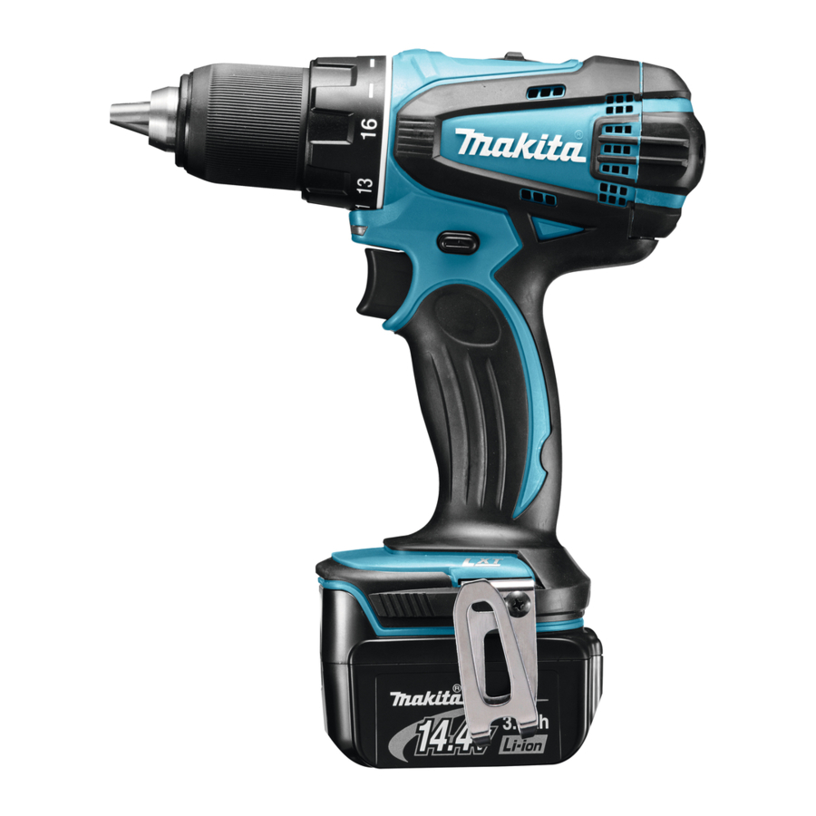
Makita BDF446; BDF456 - Cordless Driver Drill Manual
- Instruction manual (68 pages) ,
- Technical information (10 pages) ,
- Instruction manual (13 pages)
SPECIFICATIONS
| Model | BDF446 | BDF456 | |
| Capacities | Steel | 13 mm | 13 mm |
| Wood | 38 mm | 38 mm | |
| Wood screw | 6 mm x 75 mm | 10 mm x 89 mm | |
| Machine screw | M6 | M6 | |
| No load speed (min-1) | High (2) | 0 - 1,500 | 0 - 1,500 |
| Low (1) | 0 - 400 | 0 - 400 | |
| Overall length | 192 mm | 192 mm | |
| Net weight | 1.7 kg | 1.5 kg (with battery BL1815/BL1815N) 1.7 kg (with battery BL1830) | |
| Rated voltage | D.C. 14.4 V | D.C. 18 V | |
Intended use
The tool is intended for drilling and screw driving in wood, metal and plastic.
Noise
The typical A-weighted noise level determined according to EN60745:
Sound pressure level (LpA): 71 dB(A)
Uncertainty (K): 3 dB(A)
The noise level under working may exceed 80 dB (A).
Wear ear protection
Vibration
The vibration total value (tri-axial vector sum) determined according to EN60745:
Work mode: drilling into metal
Vibration emission (ah, D): 2.5 m/s2 or less
Uncertainty (K): 1.5 m/s2

General Power Tool Safety Warnings

Read all safety warnings and all instructions. Failure to follow the warnings and instructions may result in electric shock, fire and/or serious injury.
CORDLESS DRIVER DRILL SAFETY WARNINGS
- Use auxiliary handle(s), if supplied with the tool. Loss of control can cause personal injury.
- Hold power tool by insulated gripping surfaces, when performing an operation where the cutting accessory may contact hidden wiring. Cutting accessory contacting a "live" wire may make exposed metal parts of the power tool "live" and could give the operator an electric shock.
- Hold power tool by insulated gripping surfaces, when performing an operation where the fastener may contact hidden wiring. Fasteners contacting a "live" wire may make exposed metal parts of the power tool "live" and could give the operator an electric shock.
- Always be sure you have a firm footing. Be sure no one is below when using the tool in high locations.
- Hold the tool firmly.
- Keep hands away from rotating parts.
- Do not leave the tool running. Operate the tool only when hand-held.
- Do not touch the drill bit or the workpiece immediately after operation; they may be extremely hot and could burn your skin.
- Some material contains chemicals which may be toxic. Take caution to prevent dust inhalation and skin contact. Follow material supplier safety data.
DO NOT let comfort or familiarity with product (gained from repeated use) replace strict adherence to safety rules for the subject product. MISUSE or failure to follow the safety rules stated in this instruction manual may cause serious personal injury.
IMPORTANT SAFETY INSTRUCTIONS FOR BATTERY CARTRIDGE
- Before using battery cartridge, read all instructions and cautionary markings on (1) battery charger, (2) battery, and (3) product using battery.
- Do not disassemble battery cartridge.
- If operating time has become excessively shorter, stop operating immediately. It may result in a risk of overheating, possible burns and even an explosion.
- If electrolyte gets into your eyes, rinse them out with clear water and seek medical attention right away. It may result in loss of your eyesight.
- Do not short the battery cartridge:
- Do not touch the terminals with any conductive material.
- Avoid storing battery cartridge in a container with other metal objects such as nails, coins, etc.
- Do not expose battery cartridge to water or rain.
A battery short can cause a large current flow, overheating, possible burns and even a breakdown.
- Do not store the tool and battery cartridge in locations where the temperature may reach or exceed 50 ゚ C (122 ゚ F).
- Do not incinerate the battery cartridge even if it is severely damaged or is completely worn out. The battery cartridge can explode in a fire.
- Be careful not to drop or strike battery.
- Do not use a damaged battery.
- Follow your local regulations relating to disposal of battery.
Tips for maintaining maximum battery life
- Charge the battery cartridge before completely discharged. Always stop tool operation and charge the battery cartridge when you notice less tool power.
- Never recharge a fully charged battery cartridge. Overcharging shortens the battery service life.
- Charge the battery cartridge with room temperature at 10 ゚ C - 40 ゚ C (50 ゚ F - 104 ゚ F). Let a hot battery cartridge cool down before charging it.
- Charge the battery cartridge once in every six months if you do not use it for a long period of time.
FUNCTIONAL DESCRIPTION

Installing or removing battery cartridge
- Hold the tool and the battery cartridge firmly when installing or removing battery cartridge. Failure to hold the tool and the battery cartridge firmly may cause them to slip off your hands and result in damage to the tool and battery cartridge and a personal injury.
To remove the battery cartridge, slide it from the tool while sliding the button on the front of the cartridge.
To install the battery cartridge, align the tongue on the battery cartridge with the groove in the housing and slip it into place. Insert it all the way until it locks in place with a little click. If you can see the red indicator on the upper side of the button, it is not locked completely.

Battery protection system (Lithium-ion battery with star marking)
Lithium-ion batteries with a star marking are equipped with a protection system. This system automatically cuts off power to the tool to extend battery life.

The tool will automatically stop during operation if the tool and/or battery are placed under one of the following conditions:
- Overloaded:
The tool is operated in a manner that causes it to draw an abnormally high current.
In this situation, release the switch trigger on the tool and stop the application that caused the tool to become overloaded. Then pull the switch trigger again to restart.
If the tool does not start, the battery is overheated. In this situation, let the battery cool before pulling the switch trigger again. - Low battery voltage:
The remaining battery capacity is too low and the tool will not operate. In this situation, remove and recharge the battery.
Switch action
To start the tool, simply pull the switch trigger. Tool speed is increased by increasing pressure on the switch trigger. Release the switch trigger to stop.

Lighting up the front lamp
Pull the switch trigger to light up the lamp. The lamp keeps on lighting while the switch trigger is being pulled. The lamp goes out 10 -15 seconds after releasing the trigger.

NOTE:
Reversing switch action

This tool has a reversing switch to change the direction of rotation. Depress the reversing switch lever from the A side for clockwise rotation or from the B side for counterclockwise rotation.
When the reversing switch lever is in the neutral position, the switch trigger cannot be pulled.
Speed change
To change the speed, first switch off the tool and then slide the speed change lever to the "2" side for high speed or "1" side for low speed. Be sure that the speed change lever is set to the correct position before operation. Use the right speed for your job.

Adjusting the fastening torque
The fastening torque can be adjusted in 17 steps by turning the adjusting ring so that its graduations are aligned with the pointer on the tool body. The fastening torque is minimum when the number 1 is aligned with the pointer, and maximum when the ![]() marking is aligned with the pointer.
marking is aligned with the pointer.

The clutch will slip at various torque levels when set at the number 1 to 16. The clutch is designed not to slip at the ![]() marking.
marking.
Before actual operation, drive a trial screw into your material or a piece of duplicate material to determine which torque level is required for a particular application.
ASSEMBLY
Installing or removing driver bit or drill bit
Turn the sleeve counterclockwise to open the chuck jaws. Place the bit in the chuck as far as it will go. Turn the sleeve clockwise to tighten the chuck.
To remove the bit, turn the sleeve counterclockwise.

Hook
The hook is convenient for temporarily hanging the tool. This can be installed on either side of the tool.
To install the hook, insert it into a groove in the tool housing on either side and then secure it with a screw. To remove, loosen the screw and then take it out.

Installing bit holder (Optional accessory)
Fit the bit holder into the protrusion at the tool foot on either right or left side and secure it with a screw.
When not using the driver bit, keep it in the bit holders. Bits 45 mm long can be kept there.

OPERATION
Hold the tool firmly with one hand on the grip and the other hand on the bottom of the battery cartridge to control the twisting action.
Screwdriving operation
Place the point of the driver bit in the screw head and apply pressure to the tool. Start the tool slowly and then increase the speed gradually. Release the switch trigger as soon as the clutch cuts in.

NOTE:
- When driving wood screws, predrill pilot holes to make driving easier and to prevent splitting of the workpiece. See the chart.
Nominal diameter of wood screw
(mm)Recommended size of pilot hole
(mm)3.1 2.0 - 2.2 3.5 2.2 - 2.5 3.8 2.5 - 2.8 4.5 2.9 - 3.2 4.8 3.1 - 3.4 5.1 3.3 - 3.6 5.5 3.7 - 3.9 5.8 4.0 - 4.2 6.1 4.2 - 4.4
Drilling operation
First, turn the adjusting ring so that the pointer points to the ![]() marking. Then proceed as follows.
marking. Then proceed as follows.
Drilling in wood
When drilling in wood, the best results are obtained with wood drills equipped with a guide screw. The guide screw makes drilling easier by pulling the bit into the workpiece.
Drilling in metal
To prevent the bit from slipping when starting a hole, make an indentation with a center-punch and hammer at the point to be drilled. Place the point of the bit in the indentation and start drilling.
Use a cutting lubricant when drilling metals. The exceptions are iron and brass which should be drilled dry.
MAINTENANCE
Replacing carbon brushes
Replace when they wear down to the limit mark. Keep the carbon brushes clean and free to slip in the holders. Both carbon brushes should be replaced at the same time. Use only identical carbon brushes. Use a screwdriver to remove two screws then remove the rear cover.

Raise the arm part of the spring and then place it in the recessed part of the housing with a slotted bit screwdriver of slender shaft or the like.

Use pliers to remove the carbon brush caps of the carbon brushes. Take out the worn carbon brushes, insert the new ones and replace the carbon brush caps in reverse.

Make sure that the carbon brush caps have fit into the holes in brush holders securely.

Reinstall the rear cover and tighten two screws securely. To maintain product SAFETY and RELIABILITY, repairs, any other maintenance or adjustment should be performed by Makita Authorized Service Centers, always using Makita replacement parts.

OPTIONAL ACCESSORIES
If you need any assistance for more details regarding these accessories, ask your local Makita Service Center.
NOTE:
Some items in the list may be included in the tool package as standard accessories. They may differ from country to country.

Documents / ResourcesDownload manual
Here you can download full pdf version of manual, it may contain additional safety instructions, warranty information, FCC rules, etc.
Thank you! Your question has been received!


Need Assistance?
Do you have a question about the BDF446 that isn't answered in the manual? Leave your question here.