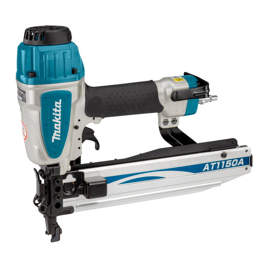
Makita AT1150A, AT2550A - Medium Crown Stapler Wide Crown Stapler Manual
- Instruction manual (97 pages) ,
- Specifications (2 pages) ,
- Parts list (1 page)
Explanation of general view


SPECIFICATIONS
| Model | AT1150A | AT2550A |
| Air pressure | 0.44 - 0.83 MPa (4.4 - 8.3 bar) | |
| Applicable staples | 25 mm - 50 mm | |
| Staple capacity | 140 pcs. | |
| Min. hose diameter | 6.5 mm | |
| Dimensions (L x W x H) | 370 mm X 87 mm X 290 mm | 370 mm X 76 mm X 260 mm |
| Net weight | 2.3 kg | 2.3 kg |
IMPORTANT SAFETY INSTRUCTIONS

WHEN USING THIS TOOL, BASIC SAFETY PRECAUTIONS SHOULD ALWAYS BE FOLLOWED TO REDUCE THE RISK OF PERSONAL INJURY, INCLUDING THE FOLLOWING:
READ ALL INSTRUCTIONS.
It is an employer's responsibility to enforce the use of safety eye protection equipment by the tool operators and by other persons in the immediate working area.
It is an employer's responsibility to enforce the use of safety eye protection equipment by the tool operators and by other persons in the immediate working area.

- General Tool Handling Guidelines:
- Never use fastener driving tools marked with the symbol "Do not use on scaffoldings, ladders" for specific application for example:
- A staple will be bent or the tool can become jammed if you mistakenly staple on top of another staple or strike a knot in the wood. The staple may be thrown and hit someone, or the tool itself can react dangerously. Place the staples with care.
- Always disconnect the air hose and remove all of the staples:
SAVE THESE INSTRUCTIONS
Symbols
The following show the symbols used for the equipment.
Be sure that you understand their meaning before use.
 | |
 | |
 | |
INSTALLATION
Selecting compressor

Select a compressor that has ample pressure and air output to assure cost-efficient operation. The graph shows the relation between stapling frequency, applicable pressure and compressor air output. Thus, for example, if stapling takes place at a rate of approximately 60 times per minute at a compression of 0.68 MPa (6.8 bar), a compressor with an air output over 90L/minute is required.
Pressure regulators must be used to limit air pressure to the rated pressure of the tool where air supply pressure exceeds the tool's rated pressure. Failure to do so may result in serious injury to tool operator or persons in the vicinity.
Selecting air hose

Fig.1
Use an air hose as large and as short as possible to assure continuous, efficient stapling operation. With an air pressure of 0.49MPa (4.9 bar), an air hose with an internal diameter of over 8.5 mm and a length of less than 20 m is recommended when the interval between each stapling is 0.5 seconds. Air supply hoses shall have a minimum working pressure rating of 1.0MPa (10 bar) or 150 percent of the maximum pressure produced in the system whichever is higher.

Lubrication

Fig.2
To insure maximum performance, install an air set (oiler, regulator, air filter) as close as possible to the tool. Adjust the oiler so that one drop of oil will be provided for every 50 staples.
When an air set is not used, oil the tool with pneumatic tool oil by placing 2 (two) or 3 (three) drops into the air fitting. This should be done before and after use. For proper lubrication, the tool must be fired a couple of times after pneumatic tool oil is introduced.
FUNCTIONAL DESCRIPTION
Adjusting depth of stapling

Fig.3
To adjust the depth of stapling, loosen the bolt by using the hex wrench provided with the tool and then slide the depth adjusting plate up or down.
If staples cannot be driven deep enough, slide the adjusting plate in the direction of arrow as shown in the figure.

Fig.4
If the staples are driven too deep, slide the adjustinhg plate in the direction of arrow as shown in the figure.

Fig.5
The depth can be adjusted 5 mm to the maximum. Tighten the bolt securely at the right position after adjusting
ASSEMBLY
Hook

Fig.6
The hook is convenient for hanging the tool temporarily. Secure the hook on the tool with the provided screw using either of two holes in the hook as shown in the figure.
Loading stapler
Select staples suitable for your work. Make sure that the hose is disconnected from the tool.
- Pull the pusher to the rear of magazine and hook the groove in the pusher on the lock pin.
![]()
Fig.7 - Insert strip of staples into the magazine. Two strips of staples can be loaded.
![]()
Fig.8 - Depress the lock pin lightly and pull the pusher to unhook it.
With the lock pin depressed, return the pusher slowly and gently to the original position.
Keep depressing the pusher until it passes through.
![]()
Fig.9


Connecting air hose

Fig.10
Slip the air socket of the air hose onto the air fitting on the stapler. Be sure that the air socket locks firmly into position when installed onto the air fitting. A hose coupling must be installed on or near the tool in such a way that the pressure reservoir will discharge at the time the air supply coupling is disconnected.
OPERATION
- Make sure all safety systems are in working order before operation.
- Pull the trigger first and then place the contact element against the workpiece.
![]()
Fig.11
![]()
Fig.12
- Pull the trigger first and then place the contact element against the workpiece.


- However when the tool is set to the "Intermittent Staplling" mode, WITH THE TRIGGER HELD IN A HALF-PULLED POSITION, an unexpected stapling could occur, if contact element is allowed to re-contact against the workpiece or the other surface under the influence of recoil. In order to avoid this unexpected stapling, perform as follows;
- Pull the trigger fully and hold it on for 1-2 seconds after stapling.
For No. 2 method, the OPTIONAL SEQUENTIAL TRIP TRIGGER (SINGLE SHOT PART) is used. Replace the trigger part with this.
- Pull the trigger fully and hold it on for 1-2 seconds after stapling.
Direction of exhaust air

Fig.13
The direction of exhaust air can be changed 360 degrees of angle by turning the exhaust cover with a hand.
Removing jammed staples
- Always disconnect the hose before removing staplers.
Remove the staples from the magazine.
Lift up the latch on the top of driver guide by hand.

Fig.14
If the latch cannot be lift up by hand, insert a slotted bit screwdriver in the gap between the latch and the door and force it up.

Fig.15
Open the door and take out staples.

Fig.16
Place the latch spring on two hooks of the driver guide and return it to its original position by pressing it.

Fig.17
MAINTENANCE
Maintenance of stapler
Always check the tool for its overall condition and loose screws before operation. Tighten as required.

Fig.18
With tool disconnected, make daily inspection to assure free movement of the contact element and trigger. Do not use tool if the contact element or trigger sticks or binds.

Fig.19
When the tool is not to be used for an extended period of time, lubricate the tool using pneumatic tool oil and store the tool in a safe place. Avoid exposure to direct sunlight and/or humid or hot environment.

Fig.20

Fig.21
Maintenance of compressor, air set and air hose

Fig.22

Fig.23
After operation, always drain the compressor tank and the air filter. If moisture is allowed to enter the tool, It may result in poor performance and possible tool failure. Check regularly to see if there is sufficient pneumatic oil in the oiler of the air set. Failure to maintain sufficient lubrication will cause O-rings to wear quickly.

Fig.24
Keep the air hose away from heat (over 60°C, over 140°F), away from chemicals (thinner, strong acids or alkalis). Also, route the hose away from obstacles which it may become dangerously caught on during operation. Hoses must also be directed away from sharp edges and areas which may lead to damage or abrasion to the hose.
To maintain product SAFETY and RELIABILITY, repairs, any other maintenance or adjustment should be performed by Makita Authorized Service Centers, always using Makita replacement parts.
ACCESSORIES
- These accessories or attachments are recommended for use with your Makita tool specified in this manual. The use of any other accessories or attachments might present a risk of injury to persons. Only use accessory or attachment for its stated purpose.
If you need any assistance for more details regarding these accessories, ask your local Makita Service Center.

Documents / ResourcesDownload manual
Here you can download full pdf version of manual, it may contain additional safety instructions, warranty information, FCC rules, etc.
Thank you! Your question has been received!


Need Assistance?
Do you have a question about the AT1150A that isn't answered in the manual? Leave your question here.