Available languages
Available languages
Quick Links
ATS 1190
ATS1192
Smart Card Reader
I
NTRODUCTION
The ATS1190/1192 Smart Card Reader is a multifunction,
all-purpose proximity card reader suitable for all locations requiring
a short-range reader. The reader can be connected directly to
the ATS Control Panel (see figure
a Menu system accessible via the BUS or by Configuration
cards programmed through Titan and the Aritech Smart Card
Programmer (ATS1621/22).
The reader operates from 9 to 14 VDC. It has a quiescent
current consumption of less than 25 mA and less than 80 mA
when reading a card. The ATS1190 is supplied standard with
a white removable dress cover, which can be interchanged with
one of four other colours available.
The ATS1192 is a heavy-duty version designed for standard
door frames.
Both the ATS1190 & ATS1192 are waterproof.
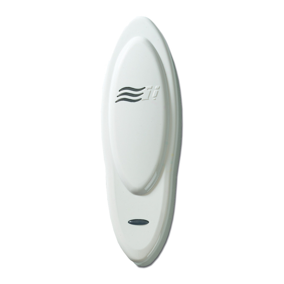
Figure
: Smart Card Reader
Blue LED:
Door open
Disarmed
M
OUNTING
The reader can be mounted on any flat surface by two pan
head screws, 3.0-3.5 mm diameter, located under the dress
cover. A slightly reduced range will be experienced when mounted
on metal surfaces. If mounting in an outdoor environment, ensure
that the blue LED is at the top.
It is not recommended to use countersunk screws.
For the ATS1190 the dress cover can be removed to expose
the mounting screw by gently prizing the sides away from the
main body to release the retaining clips and gently pulling on
the connection cord. Do not use excessive force or the reader
can be irreparably damaged.
After mounting, gently press the cover over the main body
until it locks into place.
ATS1190/1192 ATS1105 ATS1170 ATS2000/3000
Kabel
Rot
Schwarz
Grün
Weiß
Gelb
Braun
Blau
Violett
). It is configurable through
Red LED:
Door open
Armed
© 2003 GE Interlogix B.V.
All rights reserved
/4000
J2
J1
J1
12 V
12 V
12 V
0 V
0 V
0 V
D0
D0
D0
D1
D1
D1
-
L2
-
-
L1
-
-
L3
-
-
-
-
RAS
ADDRESSING
The address of the reader for BUS operations is set to the
default address RAS 16. Using a configuration card or accessing
its on-line Menu system when connected to the RS485 BUS can
change this. See the Programming Guide, Reader Address, for
further details.
T
AMPER
The reader is provided with a Tamper facility. When connected
to the BUS, Tamper data is transmitted to the Advisor Master
with system data. An external Open Collector output (violet wire)
can be configured as a Tamper control for both online and
offline operation.
R
EADER WIRING
Red:
Black:
0 Volts
Green:
D0 /
Clock
White:
D1 /
Data
Brown: LED 1
ATS1190/1192
Smart Card-Leser
D
ATS1250/1260
Tür 1, 2, 3, 4
12 V
0 V
D0
D1
L2
L1
BZ
Mit 4K7 (in Serie)
Mit 4K7 (in Serie)
zu Alarmeingang 3
zu Alarmeingang 3
Positive 9 to 14 VDC supply
DC supply ground
RS485 Data - Wiegand Data 0
Absolute maximum, 12 V @ 10 mA
RS485 Data + Wiegand Data 1
Absolute maximum, 12 V @ 10 mA
Offline LED control configured to "Two Wire
Control" will control the red LED only
Wire grounded: Red LED on
Wire open: Red LED off
Wire at +5 V to +12 V: Red LED off or,
offline LED control configured to "One
Wire Control" will control both the red
and blue LED's
Wire grounded: Blue LED on
Wire open circuit: Both LED's off
Wire at + 5 V to 12 V: Red LED on
Absolute maximum, 14 V
MAINST-ATS1190
ATS1250/1260
Localbus
Komm.
12 V
0 V
D0
D1
-
Austrittstaster
( => 0 V)
-
08/2003

Related Manuals for GE ARITECH ATS1190


Summary of Contents for GE ARITECH ATS1190
- Page 1 Wire at + 5 V to 12 V: Red LED on After mounting, gently press the cover over the main body Absolute maximum, 14 V until it locks into place. © 2003 GE Interlogix B.V. MAINST-ATS1190 All rights reserved 08/2003...
-
Page 2: Montage
Yellow: LED 2 Configurable to control the blue LED Blue: Buzzer Offline Buzzer control. when offline Wire open or +5 V to +12 V: Buzzer off Wire grounded: Blue LED on Wire grounded: Buzzer sounding Wire open: Blue LED off Absolute maximum, 14 V Wire at +5 V to +12 V: Blue LED off Violet:... - Page 3 Smart Card-lezer NLEIDING EDRADING VAN LEZER De ATS1190/1192 Smart Card-lezer is een multifunctionele, Rode: Positieve gelijkspanning tussen 9 en 14 volt universele proximity-kaartlezer die geschikt is voor alle Zwart: 0 volt Massa van voedingsgelijkspanning locaties waarop een lezer voor korte afstand is gewenst. De Groen: D0 / RS485-data –...
- Page 4 Lettore di tessere Smart Card ILI DI CABLAGGIO DEL LETTORE NTRODUZIONE Rosso: Positivo di alimentazione da 9 a 14 V Il lettore di tessere Smart Card ATS1190/1192 è un lettore Nero: 0 volts Negativo alimentazione multifunzione di tessere di prossimità, adatto a tutte le applicazioni Verde: D0 / Data - RS485;...
- Page 5 Inteligentny czytnik kart ATS1190/1192 PROWADZENIE KABLOWANIE CZYTNIKA Inteligentny czytnik kart ATS1190/1192 jest wielofunkcyjnym, Czerwony: Dodatnie napięcie zasilania 9 do 14 V DC zbliżeniowym czytnikiem kart do powszechnego zastosowania, Czarny: 0 Volts Masa zasilania prądu stałego odpowiednim do wszelkich lokalizacji wymagających czytnika Zielony: D0 / Dane RS485 - Dane 0 Wieganda.
- Page 6 Leitor Smart Card colector abertor (fio violeta) pode ser configurada como controlo NTRODUÇÃO de Tamper, tanto para operação on-line e off-line. O Leitor Smart Card ATS1190/1192 é um leitor de proximidade multifunção, indicado para todas as localizações que requerem IGAÇÕES DO EITOR um leitor de curta distância.
- Page 7 Smart Kort Leser NTRODUKSJON ABOTASJE ATS1190/1192 Smart Kort Leser er en multifunksjons, berøringsfri Leseren er utstyrt med en sabotasjebryter. Koblet til BUSS blir kortleser passende for alle plasseringer som krever en leser en sabotasje sendt til Advisor Master sammen med systemdatene. med kort rekkevidde.
-
Page 8: Lector De Tarjetas Inteligentes
Lector de tarjetas inteligentes NTRODUCCIÓN AMPER El Lector de tarjetas inteligentes ATS1190/1192 es un lector El lector se suministra con funcionalidad de tamper. Cuando de tarjetas de proximidad y multifunción de uso general, apropiado se conecta al BUS, se transmiten datos de tamper a Advisor para todas las ubicaciones que requieren un lector de corto Master con datos del sistema. - Page 9 Smart Card Læser NTRODUKTION ABOTAGE ATS1190/1192 Smart Card Læser er en multifunktions-, Læseren er forsynet med en sabotagekontakt. Ved tislutning berøringsfri kortlæser beregnet for alle placeringer hvor en via BUS bliver en aktivering af sabotage sendt til Advisor Master kort læseafstand vil dække det ønskede behov. Læseren kan centralen sammen med systemdata.
- Page 10 Smart-Card läsare NLEDNING ABLAGE Röd: + 12 V Positiv 9 till 14 VDC-matning ATS1190/1192 smart-card läsare är en universell flerfunktionsläsare för beröringsfria kort. Läsaren kan anslutas direkt till ATS Svart 0 Volt DC-matning centralapparaten (se Bild ). Man konfigurerar den via ett Grön D0 / RS485-data –...
- Page 11 Die Adresse des Lesers für den BUS-Betrieb ist auf die Standardadresse BDT 16 eingestellt. Durch Verwendung einer Konfigurationskarte oder durch Zugriff auf das Online-Menüsystem kann diese Einstellung über den RS485 BUS geändert werden. Weitere Details finden Sie im Programmierungshandbuch im Abschnitt zu Leseradressen.
- Page 12 Technische Daten Specifications Technische Specifiche Dane techniques specificaties tecniche techniczne Versorgungsspann Tension d’alimentation Voedingsspanning Tensione di Napięcie 9 – 14 V alimentazione zasilania (12 V ) (nominal) (nominale) (nomianlne) Stromaufnahme Consommation Stroomverbruik Consumo di corrente Pobór prądu – A riposo oczekiwanie 25 mA max In lettura...
- Page 13 ATS1190 ATS1192...
- Page 16 Zugelassen in / Permis en / Toegestaan in / Permesso in Österreich Liechtenstein Belgien Luxemburg Dänemark Niederlande Finnland Norwegen Frankreich Portugal Deutschland Spanien Griechenland Schweden Island Schweiz Irland Großbritannien Italien...