
Related Manuals for Honeywell ESSER 8010


Summary of Contents for Honeywell ESSER 8010
-
Page 1: Operation Instruction
Operation and Installation Instruction Extinguishing Control Computer 8010 – 19-Inch Design (Series 2 and Series 3) 798955.GB0 G 200090 Technical changes reserved! G 205064 09.2007... - Page 2 Extinguishing Control Computer 8010 – 19-Inch Intended purpose This software must only be used for the applications outlined in the catalogue and the technical description and in combination with external components and systems which have been approved and /or recommended. Warning In order to ensure correct and safe operation of the product, all guidelines concerning its transport, storage, installation, and mounting must be observed.
-
Page 3: Table Of Contents
Extinguishing Control Computer 8010 – 19-Inch Table of contents General ..................................4 Accessories / Options............................4 Display and control panel ............................5 LED indicator for zones and outputs ........................6 2.1.1 Status display of the zones......................6 2.1.2 Status display of the outputs......................7 Operating displays ............................... -
Page 4: General
Extinguishing Control Computer 8010 – 19-Inch General The Extinguishing Control Computer 8010 – 19-inch a fire alarm control panel with an integrated controller for use in extinguishing systems and provides the connection of automatic fire detectors and Manual call points. With a total of eight automatic detector zones and 30 connectable automatic fire detectors for each zone, it is possible to monitor a single extinguishing area as defined by the VdS Guideline 2496. -
Page 5: Display And Control Panel
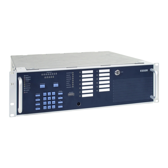
Extinguishing Control Computer 8010 – 19-Inch Display and control panel All operations of the Extinguishing Control Computer can be carried out with the clearly arranged function keys. The keys can be locked with the built-in key switch. Detector zone Relay (AE) In operation Common trouble Extinguishing system... -
Page 6: Led Indicator For Zones And Outputs
Extinguishing Control Computer 8010 – 19-Inch LED indicator for zones and outputs The status of the corresponding zone or of the output is shown with the 13 LED. The status of the 13 zones is shown in normal operation. Switchover With the key >Switchover<, it is possible to switch between indicating the zones or outputs (Toggle operation). -
Page 7: Status Display Of The Outputs
Extinguishing Control Computer 8010 – 19-Inch 2.1.2 Status display of the outputs The status of the corresponding zone or of the output is alternatively indicated with the 13 LED. The status of the 13 zones is shown in normal operation. The output indication is activated by pressing the >Switchover< key. The green LED >Output<... -
Page 8: Operating Displays
Extinguishing Control Computer 8010 – 19-Inch Operating displays The coloured LED-indicators give a quick overview of the current state of the Extinguishing Control Computer 8010. In operation Extinguishing system activated Extinguishing system enabled Emergency release Switching off Test operation Extra releasing 1 Outputs Alarm Fig. - Page 9 Extinguishing Control Computer 8010 – 19-Inch Emergency Stop (yellow LED) An already triggered extinguishing procedure is stopped during the evacuation time by the Emergency Stop zone 10. An emergency stop button of this technical zone has been pressed. Switch-off (yellow LED) Common disablement, at least one disablement was recognized.
-
Page 10: Trouble Displays
Extinguishing Control Computer 8010 – 19-Inch Trouble displays A precise determination of the failure is possible with the yellow LED of the trouble display. The LED >Trouble< has the function of a common trouble display. This LED is always activated when at least one failure has been identified in the system. - Page 11 Extinguishing Control Computer 8010 – 19-Inch Ground trouble (yellow LED) When an earth fault in the communication wiring or the supply wiring has been recognized, e.g. due to faulty insulation. Trouble (yellow LED) When the input >Trouble, extinguishing system< is activated. An extinguishing system connected to this input indicates a failure.
-
Page 12: Keypad Functions
Extinguishing Control Computer 8010 – 19-Inch Keypad functions All operations of the Extinguishing Control Computer are carried out with the clear control panel keypad. Pressing a key once is acknowledged by a short buzzer tone. When the keypad cover is closed, all keys are covered apart from the two keys >Switchover< and >Buzzer Off<. The keys can be locked with the built-in key-switch to prevent unauthorized operation. -
Page 13: Connect / Disconnect Zones
Extinguishing Control Computer 8010 – 19-Inch Connect / disconnect zones The detector zones (1 – 8) and the technical zones (9 – 13) can be switched on or off via the function keys and the ten-button keypad of the control panel. For operation, it is necessary to enable the keypad via the key-switch. -
Page 14: Connect / Disconnect Relay Outputs
Extinguishing Control Computer 8010 – 19-Inch Connect / disconnect relay outputs The relay outputs No. 1–13 can be switched on or off via the function keys and the 10-button keypad of the control panel. For operation, it is necessary to enable the keypad via the key-switch. Unlocked In operation Example: Switching off relay output No. -
Page 15: Test Mode
Extinguishing Control Computer 8010 – 19-Inch Test mode The automatic zones no. 1 - no. 8 can be switched to Test mode via the function keys and the ten-button keypad of the control panel. For operation, it is necessary to enable the keypad via the key-switch. Unlocked In operation Example: Test mode... -
Page 16: Revision Mode
Extinguishing Control Computer 8010 – 19-Inch Revision mode The Extinguishing Control Computer 8010 can be switched to the revision mode via the function keys on the operating panel. For operation, it is necessary to enable the keypad via the key-switch. Unlocked In operation The revision mode display has priority over the test mode. -
Page 17: Resetting The Panel
Extinguishing Control Computer 8010 – 19-Inch Resetting the panel The Panel can be reset via the function key of the control panel. For operation, the keypad must be enabled via the key-switch. To restart the system press the appropriate button. The internal panel status and all visual displays will be resetted. -
Page 18: Control Indicator And Alarm Counter
Extinguishing Control Computer 8010 – 19-Inch Control indicator and Alarm counter The Extinguishing Control Computer can be equipped with an optional >Control indicator and Alarm counter< (Part No. 788016). The LED indicators no. 1 to 13 lit when the corresponding detector zone or output (relating to the customer data programming) is activated. -
Page 19: Installation Instruction
Installation Instruction Extinguishing Control Computer 8010 – 19-Inch Design (Series 2 and Series 3) 798955.GB0 G 200090 Technical changes reserved! G 205064 09.2007... - Page 20 Extinguishing Control Computer 8010 – 19-Inch Table of contents Operation Instruction..............................1 Installation................................. 21 Installers responsibility............................21 Standards and guidelines ..........................22 Installation information............................24 Mechanical configuration............................26 Operating- and connecting devices........................26 19-inch rack mounting............................27 Mains connection and Protective earth (PE) ......................30 Emergency power supply ..........................
-
Page 21: Installation
Extinguishing Control Computer 8010 – 19-Inch Installation The terminal assignment and wiring illustrated in these installation instructions refer exclusively to the facilities of the operating system software for the Federal Republic of Germany [D]. The display illustration given in this manual may be differ from the real display indication due to a customized and object related configuration of the system. -
Page 22: Standards And Guidelines
Extinguishing Control Computer 8010 – 19-Inch Standards and guidelines The general technical rules must be observed when installing fire alarm systems. Any deviation from those rules is only admissible if the same degree of safety can be ensured with different means. Installations within the European Community are primarily subject to all EU regulations defining the current standards for security systems. - Page 23 Extinguishing Control Computer 8010 – 19-Inch In addition to the above, the guidelines of the German VdS Schadenverhütung GmbH (VdS) may apply for systems installed in Germany. These are examples: • VdS 2046 Safety rules for electrical power systems with voltages up to 1000 V •...
-
Page 24: Installation Information
Extinguishing Control Computer 8010 – 19-Inch Installation information The Extinguishing Control Computer 8010 – 19-Inch and 19-inch cabinet with safety glass and safety lock can be purchased without installations for self-assembly (Part No. 769163) or as a complete, pre-mounted and ready-to-connect product (Part No. - Page 25 Extinguishing Control Computer 8010 – 19-Inch Cable entry and installation Use only the proper cable entries. Use separate cable entries and cable glands for the power supply and signal lines. All connected voltage and signal lines must be installed with suitable fixing material, such as plastic cable fasteners so that they cannot move around.
-
Page 26: Mechanical Configuration
Extinguishing Control Computer 8010 – 19-Inch Mechanical configuration The Extinguishing Control Computer 8010 is suited for a direct mounting to a 19-inch rack. The arrangement of the appropriate operating elements and connectors does not require to open the housing. The housing must be opened only for the required jumper settings and to insert the batteries. All internal cable wiring is done by factory. -
Page 27: 19-Inch Rack Mounting
Extinguishing Control Computer 8010 – 19-Inch 19-inch rack mounting The following example shows the installation of an Extinguishing Control Computer in conjunction with a Fire Alarm Control panel in a common 19-inch rack. Extinguishing area 1 0 0 0 5 Extinguishing area 2 0 0 0 5 0 0 0 5... - Page 28 Extinguishing Control Computer 8010 – 19-Inch The housing of the Extinguishing Control Computer must be inserted in an appropriate 19-inch mounting slot of the cabinet and fastened by the 4 screws (see front side) from the front. To connect the zones and relay a separate 50-pole terminal card is required.
- Page 29 Extinguishing Control Computer 8010 – 19-Inch The D-SUB plugs on the housings rear side are connected via a 50-pole cable (length 1m or 2m) with the external terminal card on the C-rail. Observe the different connectors for zones (D-SUB jack) and relays (D-SUB plug) at the housings rear side when connecting the external terminal card.
-
Page 30: Mains Connection And Protective Earth (Pe)
Extinguishing Control Computer 8010 – 19-Inch Mains connection and Protective earth (PE) To ensure a proper operation of the system, the PE cable of the mains supply must be connected to the intended terminal of the Extinguishing Control Computer in accordance to the specifications given in the manual of the 19-inch rack. - Page 31 Extinguishing Control Computer 8010 – 19-Inch The power supply of the Extinguishing Control Computer 8010 is provided via the integrated power supply unit. If necessary, an increased power requirement for external devices, e.g. caused by longer cable lengths, must be compensated for with an external voltage supply via a separate power supply unit. In case of an AC main power loss, the continuous voltage supply is ensured by the batteries.
-
Page 32: Emergency Power Supply
Extinguishing Control Computer 8010 – 19-Inch Emergency power supply In case of loss of the mains voltage the control panel will be powered without a interruption by the connected battery. Depending on the capacity of the battery a backup time of up to 72 hours can be realised. After that time the external alarm devices must be still operable in an alarm condition. - Page 33 < 10,0V DC) will not charge correctly! battery Only the battery types approved from Esser by Honeywell may be used for supplying the Fire Alarm Control Panels with backup power. Observe the information and technical specifications of the battery manufacturer and the VdS-guidelines for deep charged batteries.
-
Page 34: Position And Operation Of The Devices
Extinguishing Control Computer 8010 – 19-Inch Position and operation of the devices Fig. 25: Position of the devices (Top view with open housing) Mains terminals (L1/N/PE) to connect the 230V AC mains voltage Processor board (mounted upright on the zone board) Zone board (series 2 or series 3) Operating and indicating panel board Batteries max. -
Page 35: Processor Board
Extinguishing Control Computer 8010 – 19-Inch Processor board The processor board is connected directly to the zone board by a 64 plug connector. On the processor board we find, among other things, the microprocessor for controlling the panel functions as well as the operating system and the customer data EEPROM. -
Page 36: Zone Board - Series 2
Extinguishing Control Computer 8010 – 19-Inch Zone board - series 2 The zone board - series 2 is designed for connection of eight standard detector zones for automatic detectors series 9000 and/or 9100. Refer to section 7.4.5 for additional options to connect technical alarm zones. The alarm zone operating mode (standard or EDD) is set via the associated jumpers (J1 to J8). - Page 37 Extinguishing Control Computer 8010 – 19-Inch fuse 4 A, voltage supply of the zone board + 12 V DC / GND primary fuse 1A, mains voltage 230 V AC (L1, N, PE) J1 to J8 jumper for setting the operating mode for the alarm zone inputs 1-8 Plug-in jumpers of the Std: Connection of conventional detectors, Series 9000...
-
Page 38: Detector Zones 1 To 8 (Zone Card Series 2)
Extinguishing Control Computer 8010 – 19-Inch 7.2.1 Detector zones 1 to 8 (zone card series 2) A maximum of automatic fire detectors 30 Series 9000 (Standard) with or without switch-on control (SOC) or Series 9100 (EDD) can be connected. Programming of the alarm zone operating mode (standard or EDD) is via the associated jumper. Every alarm zone must be terminated with a 10 k Ω... -
Page 39: Zone Board - Series 3
Extinguishing Control Computer 8010 – 19-Inch Zone board - series 3 The zone board - series 3 is designed for connection of 13 detector zones. Terminals 1 to 8 are suitable to connect automatic detectors and/or series 9200 / IQ8Quad (without alarm devices), technical alarm modules, as ®... - Page 40 Extinguishing Control Computer 8010 – 19-Inch Fuse 4 A, voltage supply of the zone board + 12 V DC / GND Primary fuse T 1A /H 250 V jumper open: Earth fault identification off jumper closed: Earth fault identification on (factory setting) Secondary transformer, 24 V DC, voltage supply of the zone board Mains connection terminals 230 V AC (L1, N, PE), 50 Hz Max.
- Page 41 Extinguishing Control Computer 8010 – 19-Inch Automatic Fire alarm detectors series 9200 / IQ8Quad (only LMST 8010 - series 3) Connection of max. 30. automatic Fire alarm detectors series 9200 (with integrated isolator in the detector base) or 30 Fire alarm detectors IQ8Quad without alarm device (isolator integrated by factory default) per detector zone.
- Page 42 Extinguishing Control Computer 8010 – 19-Inch Technical Alarm Modules series 9200 / IQ8TAM (only LMST 8010 - series 3) ® Required operation mode programming esserbus zone Connection of max. 30 technical alarm modules (with isolator) or IQ8TAM-modules per detector zone. Detector zone X External dry contacts (only LMST 8010 - series 3) Required operation mode programming...
-
Page 43: Terminal Assignment Of The Zones
Extinguishing Control Computer 8010 – 19-Inch Terminal assignment of the zones The external terminal card for he zone inputs of the Extinguishing Control Computer must be mounted on the C-rail of the 19-inch rack. The external terminal cards of the manufactures type „Phoenix / Weco“ or „Weidmüller“ should be used fort his purpose. -
Page 44: Zone-Terminal Card (Type Phoenix / Weco)
Extinguishing Control Computer 8010 – 19-Inch 7.4.1 Zone-terminal card (type Phoenix / Weco) 1 2 3 4 5 6 7 8 9 10 11 12 13 14 15 16 17 18 19 20 21 22 23 24 25 26 27 28 29 30 31 32 33 34 35 36 37 38 39 40 41 42 43 44 45 46 47 48 49 50 Fig. -
Page 45: Zone-Terminal Card (Type Weidmüller)
Extinguishing Control Computer 8010 – 19-Inch 7.4.2 Zone-terminal card (type Weidmüller) 2 3 4 5 6 7 8 9 10 11 12 13 14 15 16 17 18 19 20 21 22 23 24 25 G 27 28 29 30 31 32 33 34 35 36 37 38 39 40 41 42 43 44 45 46 47 48 49 50 P Fig. -
Page 46: Detector Zones 1 To 8
Extinguishing Control Computer 8010 – 19-Inch 7.4.3 Detector zones 1 to 8 Only fire alarm detector series 9000/9100 may be connected to the detector zone inputs 1 to 8 of the Extinguishing Control Computer 8010- 19-inch series 3 (refer to the appropriate section “zone board series 2 or series 3”). -
Page 47: Operating Modes Of The Detector Zones
Extinguishing Control Computer 8010 – 19-Inch 7.4.4 Operating modes of the detector zones With the operating modes of the detector zones, a distinction is made between >direct< alarming, >alarm verification> (AVer), the >Two-zone- coincidence< (2ZD) and the >Two-detector-coincidence< (2DD). Direct alarming When an alarm in this zone is triggered, the output is triggered directly without a delay. -
Page 48: Technical Zones
Extinguishing Control Computer 8010 – 19-Inch 7.4.5 Technical zones Five technical zones are available for non-automatic detectors (manual call points, push-button controls) and inputs for connecting external dry contacts. Each technical zone must be terminated in the last device with a 10 k Ω End-of-line resistor. Unused zone inputs must also be connected with a 10 k Ω... - Page 49 Extinguishing Control Computer 8010 – 19-Inch Manual detector zone Input for connecting manual call points (MCP). A fire alarm is signalled if the zone is triggered before the evacuation alarm. If the zone is triggered after the start of the evacuation alarm period, this triggering is regarded as a post- flooding command provided that the post-flooding function is enabled.
-
Page 50: Control Input Mg14 And Mg15
Extinguishing Control Computer 8010 – 19-Inch 7.4.6 Control input MG14 and MG15 Control inputs to connect external dry contact for the required switch mode. 27 28 29 30 31 32 33 34 35 36 37 38 39 40 41 42 43 44 45 46 47 48 49 50 - + - + BUZZER... -
Page 51: Power Supply Unit Board And Relay Board
Extinguishing Control Computer 8010 – 19-Inch Power supply unit board and relay board The combined power supply unit and relay board provides the entire voltage supply as well as the 13 Relay outputs for control and status functions of the Extinguishing Control Computer 8010. The 230V AC mains voltage must be connected to the appropriate terminals on the housings rear side and must NOT be connected to the power supply and relay board in the panel. - Page 52 Extinguishing Control Computer 8010 – 19-Inch Low-voltage Relay Relay 1 FuseF16 Relay 2 FuseF13 Relay 3 FuseF12 Monitoring Relay 4 FuseF11 (factory setting) T2 A /250 V Relay 5 FuseF9 dry contact Contact rating Relay 6 FuseF8 30 V DC / 2 A Relay 7 FuseF6 FuseF5...
-
Page 53: Terminal Assignment Of The Relays
Extinguishing Control Computer 8010 – 19-Inch 7.5.1 Terminal assignment of the relays The external terminal card for he relays of the Extinguishing Control Computer must be mounted on the C-rail of the 19-inch rack. The external terminal cards of the manufactures type „Phoenix / Weco“ or „Weidmüller“ should be used fort his purpose. - Page 54 Extinguishing Control Computer 8010 – 19-Inch 7.5.1.1 Relay –terminal card (type Phoenix / Weco) The terminals of the both mains voltage relay 12 and 13 are mounted at the rear side of the housing FB 798955.GB0 / 09.07...
- Page 55 Extinguishing Control Computer 8010 – 19-Inch Relay –terminal card (type Phönix / Weco) Terminal Terminal Relay 1 NC Relay 7 NC Relay 1 NO Relay 7 NO Relay 1 C/24V Relay 7 C/24V Relay 1 GND Relay 7 GND Relay 2 NC Relay 8 NC Relay 2 NO Relay 8 NO...
- Page 56 Extinguishing Control Computer 8010 – 19-Inch 7.5.1.2 Relay – terminal card (type Weidmüller) 27 28 29 30 31 32 33 34 35 36 37 38 39 40 41 42 43 44 45 46 47 48 49 50 G 2 3 4 5 6 7 8 9 10 11 12 13 14 15 16 17 18 19 20 21 22 23 24 25 P...
-
Page 57: Relay Outputs 1 To 8
Extinguishing Control Computer 8010 – 19-Inch 7.5.2 Relay outputs 1 to 8 Free programmable relays for low voltages (max. 30 V DC / 2A). The relay mode can be configured via a jumper to >positive switching/monitoring< or >dry contact<. Example with Relay 7 dry contact (Relay terminal card type Phoenix) Terminal card Power supply and relay board... - Page 58 Extinguishing Control Computer 8010 – 19-Inch In case of an associated event, the relay is activated and the voltage (24 V DC) is switched to the external unit. In the resting state, a voltage of approximately 1 V DC to 2 V DC must be present at the relay terminals during the monitored mode.
-
Page 59: Relay Outputs, 10 And 11
Extinguishing Control Computer 8010 – 19-Inch 7.5.3 Relay outputs, 10 and 11 Free programmable, dry contact relays for low voltages. The two relays 10 and 11 can be configured for the emergency operation via the appropriate jumpers. During emergency operation, the corresponding relay mode is permanently assigned to the two relays. In a CPU- failure-mode of the system these relays are activated. -
Page 60: Relay Outputs 12 And 13 (Power Supply Relay)
Extinguishing Control Computer 8010 – 19-Inch 7.5.4 Relay outputs 12 and 13 (Power supply relay) An alternating voltage up to 230 V AC can be switched with the two programmable relays 12 and 13 (NO contacts) via an external supply cable. The relay terminals are placed at the housings rear side. -
Page 61: Standardized Interface - Extinguishing
Extinguishing Control Computer 8010 – 19-Inch Standardized Interface - Extinguishing With this application it is possible to realize standardized interface >extinguishing< in accordance to the VdS 2540 requirements for Extinguishing control systems. Extinguishing control Fire Alarm Control Panel system 8010 Extinguishing command Automatic detector zone... -
Page 62: Activation Condition For The Relays (Ae)
Extinguishing Control Computer 8010 – 19-Inch Activation condition for the relays (AE) In case of an event the relay is activated relating to the selected control function in the programming software. The relays (AE) will be activated triggered to assigned switch function or respectively relay 1 to 8 relating to the programmed operation mode >dry contact<... -
Page 63: Status Functions
Extinguishing Control Computer 8010 – 19-Inch Status functions In case of an alarm event, the relay (AE) is activated relating to the status function pre selected in the customer data. The relay can be triggered via several programmed OR logic operation status functions. Common trouble The programmed relay (AE) is activated if a common trouble is recognized. - Page 64 Extinguishing Control Computer 8010 – 19-Inch Transponder trouble ® The programmed relay (AE) is triggered when a transponder trouble is recognized between the esserbus communications transponder (Part No. 781335) and the fire alarm system 8000 / IQ8Control. Customer data trouble The programmed relay (AE) is triggered when a customer data failure is recognized.
-
Page 65: Cpu-Failure Mode
Extinguishing Control Computer 8010 – 19-Inch CPU-failure mode Even in the CPU-failure mode, e.g. failure of the main processor or a trouble in the program memory, the alarm and triggering functions of the Extinguishing Control Computer can be guaranteed through the >Emergency operation trouble<... -
Page 66: Analog Loop Connection
Extinguishing Control Computer 8010 – 19-Inch Analog loop connection ® The Extinguishing Control Computer 8010 could be directly connected to the analog loop (esserbus ® esserbus -Plus) of the Fire Alarm System 8000 / IQ8Control. The analog loop terminals are located on the external terminal card of the zones. Up to eight Extinguish Control Computer 8010 (= 8 Extinguishing areas) could be connected to a single analog loop of the Fire alarm system. -
Page 67: Sequence Diagram
Extinguishing Control Computer 8010 – 19-Inch Sequence diagram 10.1 Time sequence on alarm (for Extinguishing System) Time 4 4a 8a 9 1st Alarm 2nd Alarm HA/NF Time 4 4a 8a 9 Fig. 48: Sequence diagram (Extinguishing System) FB 798955.GB0 / 09.07... - Page 68 Extinguishing Control Computer 8010 – 19-Inch Diagram names and abbreviations 1st Alarm The course of the alarm criterion HA/NF Activation(s) of manual alarm or detector/zone fire), extra releasing zone a pre-alarm exists in the extinguishing system 2nd Alarm : The course of the 2nd alarm criterion Emergency stop zone detector/zone) or direct fire alarm : Evacuation time...
- Page 69 Extinguishing Control Computer 8010 – 19-Inch Diagram times and functions Time 4 Start of release time (FZ) If the emergency stop zone has not been activated before the end of the evacuation time, this time is identical with 3; otherwise the release time starts at the end of the emergency stop activation.
-
Page 70: Time Sequence On Alarm (For Aquasafe)
Extinguishing Control Computer 8010 – 19-Inch 10.2 Time sequence on alarm (for AquaSafe) Time 12 13 Zone 1 Zone 2 Fire Time 12 13 Fig. 49: Sequence diagram (AquaSafe) Diagram names and abbreviations Zone 1 : The first zone of an alarm coincidence : The fulfilled 2-zone coincidence Zone 2 : The second zone of an alarm coincidence Fire... - Page 71 Extinguishing Control Computer 8010 – 19-Inch Diagram times and functions Time 1 1st Alarm condition fire (Zone 1) The first zone/detector detects an alarm Time 2 2nd Alarm condition Fire (Zone 2) / 2-zone coincidence (2ZD) is fulfilled • The conditions for a fire alarm (2ZD = Zone 1 + Zone 2) are fulfilled. •...
-
Page 72: Specification
Extinguishing Control Computer 8010 – 19-Inch Specification Main voltage 230 V AC Rated frequency 50 Hz Rated current 0,7 A Supply voltage for external devices 24 V DC Battery capacity 2 x 12 V / 12 Ah Battery charging voltage 13.65 V DC @ 25 °C Ambient conditions class 3k5 in accordance to DIN EN 60721-3-3... -
Page 73: Connections
Extinguishing Control Computer 8010 – 19-Inch Connections 12.1 Operation of the Extinguishing Control Computer in the Fire Alarm System 8000 / IQ8Control essernet ® esserbus ® / esserbus ® -PLus Fig. 50: Operation of the Extinguishing Control Computer in the Fire Alarm System 8000 / IQ8Control 12.2 Extinguishing Control Computer 8010 connected to the analog loop FACP 8000 / IQ8Control... -
Page 74: Third-Party Detectors Via Reset Module To Lmst 8010 - 19-Inch Series 2
Extinguishing Control Computer 8010 – 19-Inch 12.3 Third-party detectors via Reset module to LMST 8010 - 19-Inch series 2 Third-party detectors, e.g. the line-type smoke detector Fireray 50RV (Part No. 761315) or 100RV (Part No. 761316) are connected to the Extinguishing Control Computer 8010 - 19-Inch series 2 via the Reset module (Part No. -
Page 75: Third-Party Detectors Via Esserbus
Extinguishing Control Computer 8010 – 19-Inch ® 12.4 Third-party detectors via esserbus transponder to LMST 8010 - 19-Inch series 3 Third-party detectors, e.g. the line-type smoke detector Fireray 50 RV (Part No. 761315) or 100 RV ® (Part No. 761316) are connected to the Extinguishing Control Computer 8010 - series 3 via the esserbus transponder (Part No. -
Page 76: Multisector-Control
Extinguishing Control Computer 8010 – 19-Inch 12.5 Multisector-Control To create a Multisector-Control up to four Extinguishing Control Computer 8010 (LMST) may be interconnected by using the multisector interface (Part No. 788023). To realize a multisector control with up to 8 Extinguishing Control Computer 8010 a pair of two multisector interfaces is cascadable for that purpose. - Page 77 Extinguishing Control Computer 8010 – 19-Inch Example for a Multisector-Control application 8010 8010 do not connect LMST 1 +24 V DC Control valve max. 1,5 m do not connect +24 V DC LMST 2 8010 do not connect LMST 3 +24 V DC max.
- Page 78 Novar GmbH a Honeywell Company Dieselstraße 2, D-41469 Neuss Telefon: +49 (0) 21 37 / 17-0 Verwaltung Internet: www.esser-systems.de +49 (0) 21 37 / 17-600 KBC E-Mail: [email protected] Telefax: +49 (0) 21 37 / 17-286...