Table of Contents
Quick Links
g
GE Power Management
215 Anderson Avenue, Markham, Ontario
Canada L6E 1B3
Tel: (905) 294-6222 Fax: (905) 294-8512
Internet: http://www.GEindustrial.com/pm
TRANSFORMER MANAGEMENT RELAY™
INSTRUCTION MANUAL
Manual P/N: 1601-0070-B2 (GEK-106292)
Copyright © 2001 GE Power Management
745 STATUS
SYSTEM STATUS
TRANSFORMER
IN SERVICE
DE-ENERGIZED
TRANSFORMER
SELF-TEST
OVERLOAD
ERROR
LOAD-LIMIT
TEST MODE
REDUCED
DIFFERENTIAL
BLOCKED
SETPOINT GROUP 1
SETPOINT GROUP 2
SETPOINT GROUP 3
LOCAL
RESET
SETPOINT GROUP 4
MESSAGE
NEXT
PROGRAM PORT
SETPOINT
MESSAGE
ACTUAL
ESCAPE
VALUE
ENTER
g
745
Transformer Management Relay ™
GE Power Management
745
Firmware Revision: 250.000
CONDITIONS
TRIP
ALARM
PICKUP
PHASE A
PHASE B
PHASE C
GROUND
7
8
9
4
5
6
1
2
3
.
0
HELP
814768AF.CDR
Manufactured under an
ISO9001 Registered system.
Table of Contents

Related Manuals for GE 745 TRANSFORMER MANAGEMENT RELAY


Summary of Contents for GE 745 TRANSFORMER MANAGEMENT RELAY
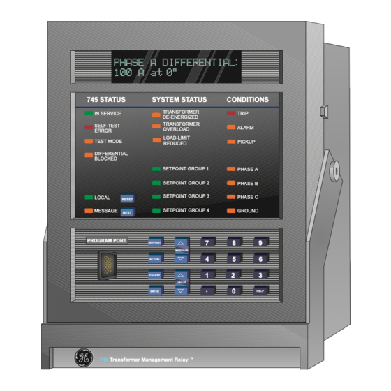
- Page 1 GE Power Management TRANSFORMER MANAGEMENT RELAY™ INSTRUCTION MANUAL Firmware Revision: 250.000 Manual P/N: 1601-0070-B2 (GEK-106292) Copyright © 2001 GE Power Management 745 STATUS SYSTEM STATUS CONDITIONS TRANSFORMER IN SERVICE TRIP DE-ENERGIZED TRANSFORMER SELF-TEST ALARM OVERLOAD ERROR LOAD-LIMIT TEST MODE PICKUP...
- Page 2 These instructions do not purport to cover all details or variations in equipment nor provide for every possible contingency to be met in connection with installation, operation, or main- tenance. Should further information be desired or should particular problems arise which are not covered sufficiently for the purchaser’s purpose, the matter should be referred to the General Electric Company.
-
Page 3: Table Of Contents
3.2.13 OUTPUT RELAYS ................... 3-11 3.2.14 SOLID STATE TRIP OUTPUT..............3-11 3.2.15 ANALOG OUTPUTS................3-11 3.2.16 RS485 / RS422 COMMUNICATION PORTS .......... 3-12 3.2.17 RS232 FRONT PANEL PROGRAM PORT ..........3-13 3.2.18 IRIG-B ...................... 3-14 GE Power Management 745 Transformer Management Relay... - Page 4 PROBLEM 1:USE OF STANDARD CT RATIOS ........5-3 b PROBLEM 2: ONLOAD TAP CHANGER ..........5-4 5.2.4 PHASE SHIFTS ON THREE-PHASE TRANSFORMERS ......5-6 5.2.5 PHASE ANGLE CORRECTION ..............5-8 5.2.6 ZERO-SEQUENCE COMPONENT REMOVAL......... 5-9 745 Transformer Management Relay GE Power Management...
- Page 5 WINDING 1 (2/3) GROUND INSTANTANEOUS OVERCURRENT 1 ..5-58 c WINDING 1 (2/3) GROUND INSTANTANEOUS OVERCURRENT 2 ..5-58 5.6.9 RESTRICTED GROUND (DIFFERENTIAL GROUND) ......5-59 a WINDING 1 (2/3) RESTRICTED GROUND FAULT ........ 5-59 GE Power Management 745 Transformer Management Relay...
- Page 6 5.9.5 IAC CURVES ................... 5-95 5.10 INVERSE VOLTS-PER-HERTZ CURVES 5.10.1 INVERSE CURVE 1................. 5-97 5.10.2 INVERSE CURVE 2................. 5-98 5.10.3 INVERSE CURVE 3................. 5-99 6. ACTUAL VALUES 6.1 OVERVIEW 6.1.1 DESCRIPTION ..................6-1 745 Transformer Management Relay GE Power Management...
- Page 7 CALIBRATION ..................6-18 6.6 TARGET MESSAGES 6.6.1 DESCRIPTION ..................6-19 6.7 SELF-TEST ERRORS 6.7.1 DESCRIPTION ..................6-21 6.7.2 MAJOR SELF-TEST ERRORS..............6-21 6.7.3 MINOR SELF-TEST ERRORS ..............6-21 6.8 FLASH MESSAGES 6.8.1 DESCRIPTION ..................6-23 GE Power Management 745 Transformer Management Relay...
- Page 8 PROTOCOLS .................... 8-1 8.1.2 PHYSICAL LAYER ..................8-1 8.2 MODBUS PROTOCOL 8.2.1 DESCRIPTION ..................8-2 8.2.2 GE POWER MANAGEMENT MODBUS PROTOCOL ......8-2 8.2.3 ELECTRICAL INTERFACE ............... 8-2 8.2.4 DATA FRAME FORMAT AND RATE ............8-2 8.2.5 DATA PACKET FORMAT ................8-3 8.2.6...
- Page 9 VERIFICATION OF SOLID STATE OUTPUT........10-15 e BASIC OPERATING TIME ..............10-16 SLOPE MEASUREMENTS..............10-16 g SLOPE KNEEPOINT ................10-17 h 2nd HARMONIC RESTRAINT ............... 10-18 5th HARMONIC RESTRAINT ..............10-18 ENERGIZATION DETECTION SCHEME..........10-19 GE Power Management 745 Transformer Management Relay...
- Page 10 10.6.15 NEGATIVE SEQUENCE INSTANTANEOUS OVERCURRENT ... 10-33 a WINDING 1 ELEMENT ................10-33 b PICKUP LEVEL ..................10-33 c OPERATING TIME ................10-34 d WINDING 2 AND 3 ELEMENTS ............10-34 10.6.16 FREQUENCY ELEMENTS ..............10-34 745 Transformer Management Relay GE Power Management viii...
- Page 11 11.1.6 S5 OUTPUTS ..................11-18 A. FIGURES AND TABLES A.1 FIGURES AND TABLES A.1.1 LIST OF FIGURES ..................A-1 A.1.2 LIST OF TABLES..................A-2 B. EU DECLARATION OF B.1 EU DECLARATION OF CONFORMITY CONFORMITY GE Power Management 745 Transformer Management Relay...
- Page 12 TABLE OF CONTENTS C. WARRANTY C.1 WARRANTY INFORMATION C.1.1 WARRANTY ....................C-1 745 Transformer Management Relay GE Power Management...
-
Page 13: Product Overview
The 745 also provides its own Waveform Capture function which will record waveform data for fault, inrush or alarm conditions. The Auto-Configuration function eliminates the need for any special CT connections by having all CTs con- nected in wye. GE Power Management 745 Transformer Management Relay... -
Page 14: Summary Of Protection Features
) Time O/C 387TG Ground Differential (Restricted Ground Fault) 151G Ground Time O/C 3THD Total Harmonic Distortion Level 187TG Ground Differential ( Restricted Ground Fault Current Demand 1THD Total Harmonic Distortion Level Current Demand 745 Transformer Management Relay GE Power Management... - Page 15 1 PRODUCT OVERVIEW 1.1 INTRODUCTION Figure 1–1: SINGLE LINE DIAGRAM GE Power Management 745 Transformer Management Relay...
-
Page 16: Order Codes
20-48 Vac @ 48-62 Hz HI = 90-300 Vdc 70-265 Vac @ 48-62 Hz OPTIONS A = ANALOG INPUT/OUTPUTS L = LOSS OF LIFE 745ORDER.CDR R = RESTRICTED GROUND FAULT Figure 1–2: 745 ORDER CODES 745 Transformer Management Relay GE Power Management... -
Page 17: Technical Specifications
LOGIC INPUTS (16) 1000 Ω maximum ON resistance (32 V DC at 2 mA provided by 745) Dry Contacts: Wet Contacts: Inputs 1 to 16: 30 to 300 V DC at 1.5 mA GE Power Management 745 Transformer Management Relay... -
Page 18: Protection Elements
4.0 x pickup:11 to 19 ms Relay Outputs 2-5: at 1.2 x pickup: 28 to 36 ms at 2.0 x pickup: 24 to 32 ms at 4.0 x pickup: 17 to 25 ms 745 Transformer Management Relay GE Power Management... - Page 19 Winding 1 phase A current / voltage Level Accuracy: ±0.02 Hz Operate Time: The operate time of the frequency trend element is variable and is dependent on the decay rate setting and the supervision frequency level. GE Power Management 745 Transformer Management Relay...
- Page 20 1.1 to 10.0 in steps of 0.1 Delay: 0 to 60000 in steps of 1 min. INSULATION AGING: LOSS OF LIFE LIMIT Pickup Level: 0 to 20000 in steps of 1 x 10 h 745 Transformer Management Relay GE Power Management...
-
Page 21: Outputs
Accuracy: OPERATING ENVIRONMENT Operating Temperature Range: –40 ° C to +60 ° C Ambient Storage Temperature: –40 ° C to +80 ° C Humidity: up to 90% non-condensing Altitude: 2000 m Pollution degree: GE Power Management 745 Transformer Management Relay... - Page 22 It is recommended that all 745 relays be powered up at least once per year to avoid deteriora- tion of electrolytic capacitors in the power supply. NOTE Specifications subject to change without notice. 1-10 745 Transformer Management Relay GE Power Management...
-
Page 23: Getting Started
This second part is the present value of the data. To view the remaining setpoints associated with the preferences sub-header, DEFAULT MESSAGE repeatedly press the key. The last message appears as shown. M E SSA G E INTENSITY:25% GE Power Management 745 Transformer Management Relay... -
Page 24: S1 745 Setup
M E SS AG E through the list of sub-header messages to the page header. As an alternative, you could press the S ETPO INT and move directly to the next page. 745 Transformer Management Relay GE Power Management... -
Page 25: Changing Setpoints
V ALU E step value, down to the minimum value. Again, continuing to press the key while at the minimum V ALU E value will continue setpoint selection from the maximum value. GE Power Management 745 Transformer Management Relay... -
Page 26: Enumeration Setpoints
Pressing SS NEW SETPOINT E N TE R E N TE R stores the new value in memory. This flash message momentarily appears to SS HAS BEEN STORED confirm the storing process. 745 Transformer Management Relay GE Power Management... -
Page 27: Text Setpoints
Re-enter the character as required. Once complete, press the key to remove the solid cursor and E S CA P E view the result. GE Power Management 745 Transformer Management Relay... -
Page 28: Security
After a few seconds, the original display returns. CHANGE PASSCODE? Press the key. As soon as a non-zero passcode is entered, setpoint M E SSA G E ALLOW ACCESS TO access will automatically become restricted. SETPOINTS? No 745 Transformer Management Relay GE Power Management... -
Page 29: Disabling/Enabling Passcode Security
It indicates E N TE R SS SETPOINT ACCESS that passcode security is now enabled. SS IS NOW RESTRICTED After a few seconds, the original display returns. ALLOW ACCESS TO SETPOINTS? No GE Power Management 745 Transformer Management Relay... - Page 30 2.3 SECURITY 2 GETTING STARTED 745 Transformer Management Relay GE Power Management...
-
Page 31: Installation
When planning the location of your panel cutout, ensure provi- sion is made for the front door to swing open without interference to or from adjacent equipment. Double Panel Single Panel Figure 3–2: SINGLE AND DOUBLE SR RELAY PANEL CUTOUT GE Power Management 745 Transformer Management Relay... -
Page 32: Case Mounting
3. With the latch raised, pull the center of the handle outward. Once disengaged, continue rotating the handle up to the stop position. Press Latch Up and Pull Handle Rotate Handle to Stop Position 745 Transformer Management Relay GE Power Management... -
Page 33: Relay Insertion
As such, a separate seal can be installed on the outside of the door to prevent it from being opened. Figure 3–5: DRAWOUT SEAL GE Power Management 745 Transformer Management Relay... -
Page 34: Typical Wiring
The information in this section will cover the important aspects of interconnections, in the general areas of instrument transformer inputs, other inputs, outputs, communications and grounding. 3.2.2 REAR TERMINAL LAYOUT Figure 3–6: REAR TERMINAL LAYOUT 745 Transformer Management Relay GE Power Management... -
Page 35: Rear Terminal Assignments
PHASE C - WINDING 3 CT SETPOINT ACCESS (–) GROUND - WINDING 1/2 CT LOGIC POWER OUT (+) CONTROL POWER (–) LOGIC POWER OUT (–) CONTROL POWER (+) indicates high side of CT and VT terminals GE Power Management 745 Transformer Management Relay... -
Page 36: Typical Wiring Diagrams
3.2 TYPICAL WIRING 3 INSTALLATION 3.2.4 TYPICAL WIRING DIAGRAMS Figure 3–7: TYPICAL WIRING DIAGRAM 745 Transformer Management Relay GE Power Management... - Page 37 3 INSTALLATION 3.2 TYPICAL WIRING Figure 3–8: TYPICAL WIRING DIAGRAM FOR GENERATOR STEP-UP GE Power Management 745 Transformer Management Relay...
-
Page 38: Phase Sequence And Transformer Polarity
The 745 has one voltage divider type input for AC voltages. There are no internal fuses or ground connections. Voltage transformers up to a maximum 5000:1 ratio may be used. The nominal secondary voltage must be in the 60 to 120 V range. 745 Transformer Management Relay GE Power Management... -
Page 39: Control Power
In addition, the negative side of the external source must be connected to the relay DC NEGATIVE rail at terminal D12. The maximum external source volt- age for this arrangement is 300 V DC. GE Power Management 745 Transformer Management Relay... -
Page 40: Analog Input
In the two-wire connection scheme, the connection from terminal B11 to B12 is made at the terminal block on the rear of the 745. This connection must not be omitted. The two-wire connection scheme does not compen- sate for the resistance of the wiring between the 745 and the RTD. 3-10 745 Transformer Management Relay GE Power Management... -
Page 41: Output Relays
For a 0 to 10 mA channel, this resistor would be 500 Ω. • For a 4 to 20 mA channel this resistor would be 250 Ω. • Figure 3–12: ANALOG OUTPUT CONNECTION GE Power Management 745 Transformer Management Relay 3-11... -
Page 42: Rs485 / Rs422 Communication Ports
An isolated power supply with an optocoupled data interface also acts to reduce noise cou- pling. To ensure maximum reliability, all equipment should have similar transient protection devices installed. Figure 3–13: RS485 CONNECTION 3-12 745 Transformer Management Relay GE Power Management... -
Page 43: Rs232 Front Panel Program Port
Modbus protocol as the two rear ports. The 745PC software required to use this interface is included with the relay. Cabling for the RS232 port is shown below for both 9 pin and 25 pin connectors. Figure 3–15: RS232 CONNECTION GE Power Management 745 Transformer Management Relay 3-13... -
Page 44: Irig-B
No special ventilation requirements need to be observed during the installation of the unit. The unit does not have to be cleaned. NOTE Hazard may result if the product is not used for its intended purpose. WARNING 3-14 745 Transformer Management Relay GE Power Management... -
Page 45: Front Panel
PROGRAM PORT SETPOINT MESSAGE ACTUAL SETPOINT ENTRY ESCAPE VALUE AND MONITOR KEYS HELP ENTER Transformer Management Relay ™ FrontPanel.CDR PROGRAM PORT INTERFACE HANDLE TO WITHDRAW RELAY TO LOCAL COMPUTER Figure 4–1: 745 FRONT PANEL GE Power Management 745 Transformer Management Relay... -
Page 46: Display
S6 TESTING/OUTPUT RELAYS/FORCE OUTPUT RELAYS FUNCTION: Enabled • • S6 TESTING/ANALOG OUTPUTS/FORCE ANALOG OUTPUTS FUNCTION: Enabled • S6 TESTING/SIMULATION/SIMULATION SETUP/SIMULATION FUNCTION: Prefault Mode / Fault Mode / Playback Mode • factory service mode is enabled 745 Transformer Management Relay GE Power Management... -
Page 47: Message
SETPOINT GROUP 4 The SETPOINT GROUP 4 indicator is on when the active setpoint group is 4. This indicator flashes when this setpoint group is being edited. GE Power Management 745 Transformer Management Relay... -
Page 48: Condition Indicators
RS232 FRONT PANEL PROGRAM PORT on page 3–13, all that is required is a connection between the relay and a computer running the 745PC software. For continuous monitoring of multiple relays, either the COM1 RS485/RS422 port or the COM2 RS485 port should be used. Figure 4–2: PROGRAM PORT 745 Transformer Management Relay GE Power Management... -
Page 49: Keypad
V AL U E increment. When the minimum value is reached, setpoint selection continues from the maximum value. Press and hold the value keys down to rapidly change values. GE Power Management 745 Transformer Management Relay... -
Page 50: Number Keys
Note that diagnostic messages for self-resetting targets disappear with the condition, but diagnostic messages for latched targets remain until they are cleared. When no targets are active, illuminates all front panel N EXT indicators for approximately 5 seconds. 745 Transformer Management Relay GE Power Management... -
Page 51: Setpoints
Output Relays SS SETPOINTS • Trace Memory Triggering SS S5 OUTPUTS • Virtual Outputs • Timers • Output Relays (Forcing) SS SETPOINTS • Analog Outputs (Forcing) SS S6 TESTING • Simulation • Factory Service GE Power Management 745 Transformer Management Relay... -
Page 52: Setpoint Entry
Passcode protection may also be enabled. When enabled, the 745 requests a numeric passcode before any setpoint can be entered. As an additional safety measure, a minor self-test error is generated when the pass- code is entered incorrectly three times in a row. 745 Transformer Management Relay GE Power Management... -
Page 53: Auto-Configuration
= Winding 2 nominal voltage Thus, for any load, the Winding 2 CT secondary current is higher (per unit) than the Winding 1 CT secondary current. The mismatch factor is 1594.2 / 1500 = 1.063. GE Power Management 745 Transformer Management Relay... -
Page 54: Problem 2: Onload Tap Changer
The 745 allows monitoring of the tap changer position via the tap position input. With this input, the 745 dynam- ically adjusts the CT ratio mismatch factor based on the actual transformer voltage ratio set by the tap changer. 745 Transformer Management Relay GE Power Management... - Page 55 CHANGER: Winding 2 NUMBER OF TAP POSITIONS: 33 MINIMUM TAP POSITION VOLTAGE: 61.0 kV VOLTAGE INCREMENT PER TAP: 0.50 kV Maximum value resistance on top tap is 5 KΩ RESISTANCE INCREMENT PER TAP: 33 Ω GE Power Management 745 Transformer Management Relay...
-
Page 56: Phase Shifts On Three-Phase Transformers
The source phase sequence must be stated when describing the winding phase relationships since these rela- tionships change when the phase sequence changes. The example below shows why this happens, using a transformer described in IEC nomenclature as "Yd1" or in GE Power Management nomenclature as "Y/d30." Figure 5–2: EXAMPLE TRANSFORMER The above figure shows the physical connections within the transformer that produce a phase angle in the delta winding that lags the respective wye winding by 30°. - Page 57 Note that the Delta winding currents leads the Wye winding currents by 30°, (which is a type Yd11 in IEC nomenclature and a type Y/d330 in GE Power Management nomenclature) which is in disagreement with the transformer nameplate. This is because the physical connections and hence the equations used to calculate current for the delta winding have not changed.
-
Page 58: Phase Angle Correction
TRANSFORM CONNECTIO VOLTAGE PHASE reference phase ER TYPE PHASORS SHIFT Y/d30° 30° lag (gnd 1/2) phase angle correction (or phase shift) DELTA 0° that is performed internally to calculate 30° lag differential currents 745 Transformer Management Relay GE Power Management... -
Page 59: Zero-Sequence Component Removal
The 745 removes zero-sequence current from all windings of Wye/Wye and Wye/Wye/Wye transformers to prevent possible relay maloperations resulting from these two conditions. GE Power Management 745 Transformer Management Relay... -
Page 60: Transformer Types Table
D/d180° Y/d150° DELTA 0° DELTA 180° lag 0° 150° lag 240° DELTA 210° (gnd 1/2) D/d240° Y/d210° DELTA 0° 240° lag DELTA 0° 210° lag 300° DELTA D/d300° DELTA 0° 300° lag 5-10 745 Transformer Management Relay GE Power Management... - Page 61 ZIG-ZAG Y/z150° (gnd 1/2) 0° ZIG-ZAG 240° lag (gnd 2/3) 0° 150° lag 300° DELTA 210° D/z300° (gnd 1/2) ZIG-ZAG (gnd 1/2) 0° Y/z210° 300° lag ZIG-ZAG (gnd 2/3) 0° 210° lag GE Power Management 745 Transformer Management Relay 5-11...
- Page 62 0° 0° 150° lag 150° lag 210° 210° (gnd 1/2) (gnd 1/2) 210° 30° Y/y180°/ (gnd 2/3) Y/y0°/d210° (gnd 2/3) d210° 0° 180° lag DELTA DELTA 0° 0° 210° lag 210° lag 5-12 745 Transformer Management Relay GE Power Management...
- Page 63 DELTA 60° lag 180° lag 330° lag 30° lag 150° (gnd 1/2) (gnd 1/2) DELTA 0° Y/d30°/d30° DELTA 30° lag Y/d150°/y0° 0° 150° lag DELTA 0° 150° 30° lag (gnd 2/3) 0° GE Power Management 745 Transformer Management Relay 5-13...
- Page 64 30° lag 0° 150° lag 180° lag 210° 150° (gnd 1/2) (gnd 1/2) DELTA DELTA Y/d150°/ 0° Y/d210°/d30° 0° 210° lag 150° lag d210° DELTA 180° DELTA 300° 30° lag 210° lag 5-14 745 Transformer Management Relay GE Power Management...
- Page 65 180° DELTA 240° 150° lag 330° lag 330° 330° (gnd 1/2) (gnd 1/2) DELTA Y/d330°/ DELTA 0° Y/d330°/y0° 0° 330° lag d210° 330° lag DELTA 120° 330° (gnd 2/3) 210° lag 0° GE Power Management 745 Transformer Management Relay 5-15...
- Page 66 60° lag 0° DELTA 0° DELTA 300° lag 0° 60° lag DELTA 0° 120° DELTA DELTA 0° D/d0°/y30° DELTA 120° 0° D/d0°/d120° 0° 330° (gnd 2/3) DELTA 0° 30° lag 120° lag 5-16 745 Transformer Management Relay GE Power Management...
- Page 67 DELTA 60° lag DELTA 300° D/d60°/y210° 60° lag DELTA D/d60°/d0° 0° 60° lag 150° (gnd 2/3) 210° lag DELTA 60° lag 0° 120° DELTA DELTA D/d120°/d0° 0° 120° lag DELTA 120° 0° GE Power Management 745 Transformer Management Relay 5-17...
- Page 68 D/d120°/ 240° DELTA D/d180°/ 180° 120° lag y330° 180° lag y150° (gnd 2/3) 30° lag 210° 330° lag (gnd 2/3) 150° lag 180° DELTA DELTA D/d180°/d0° 0° 180° lag DELTA 180° 0° 5-18 745 Transformer Management Relay GE Power Management...
- Page 69 DELTA 0° DELTA 300° 240° lag 60° lag DELTA 0° DELTA 0° DELTA 120° D/d240°/y30° 240° lag 330° D/y30°/d240° (gnd 1/2) 30° lag 330° (gnd 2/3) DELTA 120° 30° lag 240° lag GE Power Management 745 Transformer Management Relay 5-19...
- Page 70 150° lag 0° 0° DELTA 0° DELTA 0° D/y150°/ 210° (gnd 1/2) D/y150°/ y330° 210° 150° lag (gnd 1/2) d120° 150° lag (gnd 2/3) 30° lag DELTA 240° 330° lag 120° lag 5-20 745 Transformer Management Relay GE Power Management...
- Page 71 240° 240° lag 120° lag DELTA 0° DELTA 0° 150° (gnd 1/2) D/y210°/y30° D/y330°/ (gnd 1/2) 30° lag 210° lag d180° 330° lag 330° (gnd 2/3) DELTA 180° 30° lag 180° lag GE Power Management 745 Transformer Management Relay 5-21...
- Page 72 150° lag DELTA 0° D/y330°/ (gnd 1/2) 30° lag y330° 330° lag (gnd 2/3) 30° lag 330° lag 30° lag ZIG-ZAG (gnd 1/2) 0° Y/z30°/z30° 30° lag ZIG-ZAG (gnd 2/3) 0° 30° lag 5-22 745 Transformer Management Relay GE Power Management...
-
Page 73: Table Of Phase Shifts
150° lag 330° lag b = (C – B) / √3 b = (B – C) / √3 c = (A – C) / √3 c = (C – A) / √3 GE Power Management 745 Transformer Management Relay 5-23... -
Page 74: S1 745 Setup
Factory default passcode: 0 ENCRYPTED PASSCODE: If the programmed passcode is unknown, consult the factory service AIKFBAIK department with the encrypted passcode. The passcode can be determined using a deciphering program. 5-24 745 Transformer Management Relay GE Power Management... -
Page 75: Preferences
When interacting with the display using the front panel keys, the display will always operate at full brightness. One of five settings can be selected for attenuation of default messages: 100% (maximum), 75%, 50%, 25%, or 0% (minimum). GE Power Management 745 Transformer Management Relay 5-25... -
Page 76: Communications
Range: None / Even / Odd FRONT PARITY: Select the parity type for the front panel port. This setpoint cannot be None changed via the communication ports. 5-26 745 Transformer Management Relay GE Power Management... -
Page 77: Dnp Communications
Enabling this setpoint will cause the cold restart request to initialize only the DNP sub-module. When "Disabled" is selected, a cold restart request will cause loss of protection until the 745 reset completes. WARNING GE Power Management 745 Transformer Management Relay 5-27... -
Page 78: Resetting
Range: None / DC Shift / Amplitude Modulated IRIG-B SIGNAL TYPE: Select the type of IRIG-B signal being used for clock synchronization. Select None ‘None’ if no IRIG-B signal is to be used. 5-28 745 Transformer Management Relay GE Power Management... -
Page 79: Default Messages
The message is now removed from the default message list E N TE R and the messages that follow are moved up to fill the gap. GE Power Management 745 Transformer Management Relay 5-29... -
Page 80: Scratchpad
745 is set to Programmed. The setpoint is defaulted to Not Programmed when the relay leaves the factory. The following self-test error message is displayed automatically until the 745 is put into the programmed state: S SETPOINTS HAVE NOT S BEEN PROGRAMMED 5-30 745 Transformer Management Relay GE Power Management... -
Page 81: Options
ENABLE ANALOG I/O? Range: Yes / No ENABLE LOSS OF LIFE? Range: Yes / No ENABLE RESTRICTED GROUND FAULT? Yes Enter passcode supplied by the manufacturer. ENTER PASSCODE: Range: Yes / No UPGRADE OPTIONS? GE Power Management 745 Transformer Management Relay 5-31... - Page 82 745 to upgrade its options. A flash message EN TE R appears indicating the results of the upgrade. A successful upgrade may be verified by examining the installed options display under A4 PRODUCT INFO/ REVISION CODES/INSTALLED OPTIONS. 5-32 745 Transformer Management Relay GE Power Management...
-
Page 83: S2 System Setup
•DELTA connected current transformers on the WYE side of the power transformer (4000:5 ratio) Set: TRANSFORMER TYPE = 2W External Connection WINDING 1 PHASE CT PRIMARY = 25000:5 WINDING 2 PHASE CT PRIMARY = (4000 / ):5 or 2309:5 GE Power Management 745 Transformer Management Relay 5-33... - Page 84 0.001 KW No load Loss 0.1 to 2000.0 0.01 to 200.00 0.001 to 20.000 in steps of 1 KW in steps of 0.1 KW in steps of 0.01 KW 5-34 745 Transformer Management Relay GE Power Management...
-
Page 85: Winding 1 (2/3)
The above setpoint options are also available for the second and third winding. W3 setpoints are only visible if the unit has the appropriate hardware and if the selected transformer type is 3-winding. NOTE GE Power Management 745 Transformer Management Relay 5-35... -
Page 86: Onload Tap Changer
Range: 10 to 500 (steps of 1) RESISTANCE INCREMENT PER TAP: 33 Ω Enter the resistance increment that the 745 will see for each tap increment. Maximum value resistance on top tap is 5 KΩ 5-36 745 Transformer Management Relay GE Power Management... -
Page 87: Harmonics
Enter the trip time for 1.03 times the pickup level for curve A (B/C). The 1.03 x PU: 0 ms messages that follow sequentially, correspond to the trip times for the various pickup levels as indicated above. GE Power Management 745 Transformer Management Relay 5-37... -
Page 88: Voltage Input
NOMINAL VT SECONDARY Enter the nominal secondary voltage (in volts) of the voltage transformer. VOLTAGE: 120.0 V Range: 1 to 5000 (steps of 1) VT RATIO: Enter the ratio of the voltage transformer. 1000:1 5-38 745 Transformer Management Relay GE Power Management... -
Page 89: Ambient Temperature
Monthly Average . Ambient temperature is used in the calculation of Insulation Aging and must be enabled for the function to operate. There is a display for each month similar to the box above. NOTE GE Power Management 745 Transformer Management Relay 5-39... -
Page 90: Analog Input
Range: 0 to 65000 (steps of 1) ANALOG INPUT MAXIMUM 1000 µA Enter the value of the quantity measured which corresponds to the VALUE: maximum output value of the transducer. 5-40 745 Transformer Management Relay GE Power Management... -
Page 91: Demand Metering
This message is displayed only when the CURRENT DEMAND METER TYPE is 20 min. set for Block Interval or Rolling Demand. Enter the time period over which the current demand calculation is performed. GE Power Management 745 Transformer Management Relay 5-41... -
Page 92: Analog Outputs
Range: matches the range of the associated actual value ANALOG OUTPUT 1 Enter the value of the selected parameter which corresponds to the MAX: 1000 A maximum output current of analog output 1 (2-7). 5-42 745 Transformer Management Relay GE Power Management... -
Page 93: Setpoints S3 Logic Inputs
Select Closed as the input asserted state when connected to a normally open STATE: Closed contact (where the signaling state is closed). Select Open when connected to a normally closed contact (where the signaling state is open). GE Power Management 745 Transformer Management Relay 5-43... -
Page 94: Virtual Inputs
Range: Not Asserted / Asserted INPUT 1 PROGRAMMED Select Asserted to place the virtual input in the signaling state. Select Not STATE: Not Asserted Asserted to place the virtual input in the non-signaling state. 5-44 745 Transformer Management Relay GE Power Management... -
Page 95: S4 Elements
745. Selecting an output relay or virtual output allows the element to be blocked based on conditions detected by the 745 and the combination of logic programmed in the associated FlexLogic™ equation. GE Power Management 745 Transformer Management Relay 5-45... -
Page 96: Setpoint Group
CT ratio mismatch (not a factor, since the 745 automatically corrects for this mismatch) • Onload tap changers which result in dynamically changing CT mismatch • CT accuracy errors • CT saturation 5-46 745 Transformer Management Relay GE Power Management... - Page 97 + sign to obtain the differential current. NOTE 200% (x CT) differential SLOPE 2 OPERATE 100% REGION 100% SLOPE 1 RESTRAINT 1.00 REGION PICKUP 0.30 0.05 (x CT) restraint KNEEPOINT Figure 5–7: PERCENT DIFFERENTIAL – DUAL SLOPE CHARACTERISTIC GE Power Management 745 Transformer Management Relay 5-47...
-
Page 98: Percent Differential
98% Range: Disabled / Logc Inpt 1 (2-16) /Virt Inpt 1 (2-16) / Output Rly 1 (2-8) / PERCENT DIFFERENTIAL SelfTest Rly / Virt Outpt 1 (2-5) BLOCK: Disabled 5-48 745 Transformer Management Relay GE Power Management... -
Page 99: Harmonic Inhibit
Energization inhibit settings are put in service upon detection of de-energization. Upon energization, the ener- gization inhibit duration timer is initiated and the settings are removed from service when the time delay elapses. GE Power Management 745 Transformer Management Relay 5-49... -
Page 100: Energization Inhibit
Enter the level of current below which the transformer is considered de- CURRENT: 0.10 x CT energized (energization sensing by current enabled), and above which the transformer is considered energized (any energization sensing enabled). 5-50 745 Transformer Management Relay GE Power Management... -
Page 101: E 5Th Harmonic Inhibit
Range: 0.1 to 65.0 (steps of 0.1) 5th HARMONIC INHIBIT LEVEL: 10.0% ƒο Enter the level of 5th harmonic current above which the percent differential element will be inhibited from operating. GE Power Management 745 Transformer Management Relay 5-51... -
Page 102: Instantaneous Differential
W1 PHASE TIME OC Enter the phase current level (in units of relay nominal current) above which PICKUP: 1.20 x CT the W1 (2/3) phase time overcurrent element will pickup and start timing. 5-52 745 Transformer Management Relay GE Power Management... - Page 103 ANSI / IEEE C57.110-1986) and, when this feature is enabled, automatically shifts the phase time overcurrent curve pickup in order to maintain the required protection margin with respect to the transformer thermal damage curve, as illustrated below. Figure 5–8: HARMONIC DERATING CORRECTION GE Power Management 745 Transformer Management Relay 5-53...
-
Page 104: B Winding 1 (2/3) Phase Instantaneous Overcurrent 1
, or press E N TE R to go to the next section. M E SSA G E The messages that follow are identical to those described for PHASE INSTANTANEOUS OVERCURRENT 1 above. NOTE 5-54 745 Transformer Management Relay GE Power Management... -
Page 105: Neutral Overcurrent
Range: Disabled / Logc Inpt 1 (2-16) /Virt Inpt 1 (2-16) / Output Rly 1 (2-8) / W1 NEUTRAL TIME OC SelfTest Rly / Virt Outpt 1 (2-5) BLOCK: Disabled GE Power Management 745 Transformer Management Relay 5-55... -
Page 106: B Winding 1 (2/3) Neutral Instantaneous Overcurrent 1
, or press E N TE R to go to the next section. M E SSA G E The messages that follow are identical to those described for NEUTRAL INSTANTANEOUS OVERCURRENT 1. NOTE 5-56 745 Transformer Management Relay GE Power Management... -
Page 107: Ground Overcurrent
Range: Disabled / Logc Inpt 1 (2-16) /Virt Inpt 1 (2-16) / Output Rly 1 (2-8) / W1 GROUND TIME OC SelfTest Rly / Virt Outpt 1 (2-5) BLOCK: Disabled GE Power Management 745 Transformer Management Relay 5-57... -
Page 108: Winding 1 (2/3) Ground Instantaneous Overcurrent 1
, or press E N TE R to go to the next section. M E SSA G E The messages that follow are identical to those described for GROUND INSTANTANEOUS OVERCURRENT 1. NOTE 5-58 745 Transformer Management Relay GE Power Management... -
Page 109: Restricted Ground (Differential Ground)
It is intended to provide sensitive ground fault detection for low magnitude fault currents which would not be detected by the percent differential element. Delta Winding Wye Winding FAULT Impedance grounded wye winding Figure 5–10: RESISTANCE GROUNDED WYE WINDING GE Power Management 745 Transformer Management Relay 5-59... - Page 110 CTs used. Typically no more than 4% overall error due to CT "spill" is assumed for protection class CTs at nominal load. 5-60 745 Transformer Management Relay GE Power Management...
-
Page 111: B Restricted Ground Fault Settings Example
Pickup Setting ---------------------- - ----------- - CT Ratio 50 A Slope 9.5% (select Slope Setting = 9%) ---------- - --------------- - 525 A Time Delay: dependent on downstream protection coordination (100 ms typical) GE Power Management 745 Transformer Management Relay 5-61... -
Page 112: C Setpoints
Range: Disabled / Logc Inpt 1 (2-16) /Virt Inpt 1 (2-16) / Output Rly 1 (2-8) / W1 RESTD GND FAULT SelfTest Rly / Virt Outpt 1 (2-5) BLOCK: Disabled 5-62 745 Transformer Management Relay GE Power Management... -
Page 113: Negative Sequence Overcurrent
Range: Disabled / Logc Inpt 1 (2-16) /Virt Inpt 1 (2-16) / Output Rly 1 (2-8) / W1 NEG SEQ TIME OC SelfTest Rly / Virt Outpt 1 (2-5) BLOCK: Disabled GE Power Management 745 Transformer Management Relay 5-63... -
Page 114: Winding 1 (2/3) Neg. Seq. Instantaneous Overcurrent
Range: Disabled / Logc Inpt 1 (2-16) /Virt Inpt 1 (2-16) / Output Rly 1 (2-8) / W1 NEG SEQ INST OC SelfTest Rly / Virt Outpt 1 (2-5) BLOCK: Disabled 5-64 745 Transformer Management Relay GE Power Management... -
Page 115: Frequency
Range: 45.00 to 59.99 (steps of 0.01) UNDERFREQUENCY 1 Enter the frequency (in Hz) below which the Underfrequency 1 element will PICKUP: 59.00 Hz pickup and start the delay timer. GE Power Management 745 Transformer Management Relay 5-65... -
Page 116: Frequency Decay
RATE 4: 4.0 Hz/s Range: Disabled / Logc Inpt 1 (2-16) /Virt Inpt 1 (2-16) / Output Rly 1 (2-8) / FREQUENCY DECAY SelfTest Rly / Virt Outpt 1 (2-5) BLOCK: Disabled 5-66 745 Transformer Management Relay GE Power Management... -
Page 117: Overfrequency
DELAY: 5.00 s the element operates. Range: Disabled / Logc Inpt 1 (2-16) /Virt Inpt 1 (2-16) / Output Rly 1 (2-8) / OVERFREQUENCY SelfTest Rly / Virt Outpt 1 (2-5) BLOCK: Disabled GE Power Management 745 Transformer Management Relay 5-67... -
Page 118: Overexcitation
Range: Disabled / Logc Inpt 1 (2-16) /Virt Inpt 1 (2-16) / Output Rly 1 (2-8) / 5th HARMONIC LEVEL SelfTest Rly / Virt Outpt 1 (2-5) BLOCK: Disabled 5-68 745 Transformer Management Relay GE Power Management... -
Page 119: Volts-Per-Hertz 1 (2)
Range: Disabled / Logc Inpt 1 (2-16) /Virt Inpt 1 (2-16) / Output Rly 1 (2-8) / VOLTS-PER-HERTZ 1 SelfTest Rly / Virt Outpt 1 (2-5) BLOCK: Disabled GE Power Management 745 Transformer Management Relay 5-69... -
Page 120: Harmonics
Range: Disabled / Logc Inpt 1 (2-16) /Virt Inpt 1 (2-16) / Output Rly 1 (2-8) / W1 THD LEVEL SelfTest Rly / Virt Outpt 1 (2-5) BLOCK: Disabled 5-70 745 Transformer Management Relay GE Power Management... -
Page 121: Winding 1 (2/3) Harmonic Derating
Range: Disabled / Logc Inpt 1 (2-16) /Virt Inpt 1 (2-16) / Output Rly 1 (2-8) / W1 HARMONIC DERATING SelfTest Rly / Virt Outpt 1 (2-5) BLOCK: Disabled GE Power Management 745 Transformer Management Relay 5-71... -
Page 122: Insulation Aging / Loss Of Life Feature
The element operates on the computed hottest-spot value. The Hottest-spot temperature will revert to 0°C for 1 minute if the power supply to the relay is interrupted. The necessary settings required for this element to per- form correctly are entered under: S4 ELEMENTS/INSULATION AGING/HOTTEST-SPOT LIMIT 5-72 745 Transformer Management Relay GE Power Management... -
Page 123: Hottest-Spot Limit
Range: Disabled / Logc Inpt 1 (2-16) /Virt Inpt 1 (2-16) / Output Rly 1 (2-8) / HOTTEST-SPOT LIMIT SelfTest Rly / Virt Outpt 1 (2-5) BLOCK: Disabled GE Power Management 745 Transformer Management Relay 5-73... -
Page 124: Aging Factor Limit
DELAY: 10 min. element operates. Range: Disabled / Logc Inpt 1 (2-16) /Virt Inpt 1 (2-16) / Output Rly 1 (2-8) / AGING FACTOR LIMIT SelfTest Rly / Virt Outpt 1 (2-5) BLOCK: Disabled 5-74 745 Transformer Management Relay GE Power Management... -
Page 125: Loss Of Life Limit
LOSS OF LIFE LIMIT SelfTest Rly / Virt Outpt 1 (2-5) BLOCK: Disabled The actual values are only displayed if the Loss of Life option is installed and the ambient temperature is enabled. NOTE GE Power Management 745 Transformer Management Relay 5-75... -
Page 126: Analog Input
Range: Disabled / Logc Inpt 1 (2-16) /Virt Inpt 1 (2-16) / Output Rly 1 (2-8) / ANALOG INPUT LEVEL 1 SelfTest Rly / Virt Outpt 1 (2-5) BLOCK: Disabled 5-76 745 Transformer Management Relay GE Power Management... -
Page 127: Current Demand
Range: Disabled / Logc Inpt 1 (2-16) /Virt Inpt 1 (2-16) / Output Rly 1 (2-8) / W1 CURRENT DEMAND SelfTest Rly / Virt Outpt 1 (2-5) BLOCK: Disabled GE Power Management 745 Transformer Management Relay 5-77... -
Page 128: Transformer Overload
Select any logic input that, when asserted, indicates the transformer cooling SIGNAL: Disabled system has failed and an over-temperature condition exists. The logic input should be connected to the transformer winding temperature alarm contacts. 5-78 745 Transformer Management Relay GE Power Management... -
Page 129: Tap Changer Failure
DELAY: 5.00 s Range: Disabled / Logc Inpt 1 (2-16) /Virt Inpt 1 (2-16) / Output Rly 1 (2-8) / TAP CHANGER FAILURE SelfTest Rly / Virt Outpt 1 (2-5) BLOCK: Disabled GE Power Management 745 Transformer Management Relay 5-79... -
Page 130: S5 Outputs
Virtual Output 2 (for use in other equations) Virtual Output 3 Virtual Output 4 Virtual Output 5 * cycle refers to the power system cycle as detected by the frequency circuitry of the 745. 5-80 745 Transformer Management Relay GE Power Management... - Page 131 2 to 9 (for 10 parameter equations) Inputs and gates are combined into a FlexLogic™ equation. The sequence of entries in the linear array of parameters follows the general rules listed in the following section. GE Power Management 745 Transformer Management Relay 5-81...
-
Page 132: Flexlogic™ Rules
1. For all these gates, the inputs precede the gate itself. This ordering of parameters of an equation, where the gate (or “operator”) follows the input (or “value”) is com- monly referred to as “Postfix” or “Reverse Polish” notation. 5-82 745 Transformer Management Relay GE Power Management... - Page 133 Any equation entered in the 745 that does not make logical sense according to the notation described here, will be flagged as a self-test error. The following message will be displayed until the error is corrected: S SELF-TEST ERROR: S Flexlogic Eqn GE Power Management 745 Transformer Management Relay 5-83...
-
Page 134: Output Relays
Any W1 OC OP OR (2 inputs) Xfmr Overload OP OR (2 inputs) OR (2 inputs) Any W2 OC OP 5th HarmLevel OP OR (4 inputs) OR (4 inputs) 06 to 20 5-84 745 Transformer Management Relay GE Power Management... -
Page 135: Trace Memory
Range: any FlexLogic™ input or gate VIRTUAL 1 FLEXLOGIC The following 10 messages are the parameters of the FlexLogic™ equation 01: END for virtual output 1 (2-5) as described in the introduction to FlexLogic™. GE Power Management 745 Transformer Management Relay 5-85... -
Page 136: Timers
TIMER 1 DROPOUT Enter the delay time after which the start condition for timer 1 (2-10) must DELAY: 0.00 s remain not operated or not asserted, before the timer will stop operating. 5-86 745 Transformer Management Relay GE Power Management... -
Page 137: S6 Testing
For example, if the analog output range has been programmed to 4-20 mA, entering 100% outputs 20 mA, 0% outputs 4 mA, and 50% outputs 12 mA. This setpoint is only operational if analog output testing is enabled. GE Power Management 745 Transformer Management Relay 5-87... -
Page 138: Simulation
Range: Disabled / Logc Inpt 1 (2-16) START PLAYBACK MODE Select any logic input which, when asserted, initiates Playback Mode SIGNAL: Disabled simulation. This signal has an effect only if the 745 is initially in Prefault Mode. 5-88 745 Transformer Management Relay GE Power Management... -
Page 139: Prefault Values
Prefault Mode. Range: 0.0 to 2.0 (steps of 0.1) VOLTAGE INPUT Enter the voltage magnitude (in terms of the nominal VT secondary voltage) MAGNITUDE: 1.0 x VT while in Prefault Mode. GE Power Management 745 Transformer Management Relay 5-89... -
Page 140: Fault Values
S FACTORY SERVICE these setpoints press or press for the next section. S [ENTER] for more EN TE R M E SSA G E (Restricted Access For Factory Personnel Only) ENTER FACTORY PASSCODE: 5-90 745 Transformer Management Relay GE Power Management... -
Page 141: Time Overcurrent Curves 5.9.1 Note
ANSI CURVE SHAPE CONSTANTS EXTREMELY INVERSE 0.0399 0.2294 0.5000 3.0094 0.7222 VERY INVERSE 0.0615 0.7989 0.3400 –0.2840 4.0505 NORMALLY INVERSE 0.0274 2.2614 0.3000 –4.1899 9.1272 MODERATELY INVERSE 0.1735 0.6791 0.8000 –0.0800 0.1271 GE Power Management 745 Transformer Management Relay 5-91... - Page 142 0.986 8.106 4.544 2.866 2.291 1.994 1.812 1.689 1.600 1.532 1.479 10.807 6.059 3.821 3.054 2.659 2.416 2.252 2.133 2.043 1.972 10.0 13.509 7.574 4.776 3.818 3.324 3.020 2.815 2.666 2.554 2.465 5-92 745 Transformer Management Relay GE Power Management...
-
Page 143: Definite Time Curve
Table 5–12: IEC CURVE CONSTANTS IEC (BS) CURVE SHAPE CONSTANTS IEC CURVE A (BS142) 0.140 0.020 IEC CURVE B (BS142) 13.500 1.000 IEC CURVE C (BS142) 80.000 2.000 IEC SHORT INVERSE 0.050 0.040 GE Power Management 745 Transformer Management Relay 5-93... - Page 144 1.835 1.067 0.668 0.526 0.451 0.404 0.371 0.346 0.327 0.311 0.80 2.446 1.423 0.890 0.702 0.602 0.538 0.494 0.461 0.435 0.415 1.00 3.058 1.778 1.113 0.877 0.752 0.673 0.618 0.576 0.544 0.518 5-94 745 Transformer Management Relay GE Power Management...
-
Page 145: Iac Curves
CONSTANTS IAC EXTREME INVERSE 0.0040 0.6379 0.6200 1.7872 0.2461 IAC VERY INVERSE 0.0900 0.7955 0.1000 –1.2885 7.9586 IAC INVERSE 0.2078 0.8630 0.8000 –0.4180 0.1947 IAC SHORT INVERSE 0.0428 0.0609 0.6200 –0.0010 0.0221 GE Power Management 745 Transformer Management Relay 5-95... - Page 146 0.197 0.859 0.569 0.419 0.368 0.341 0.325 0.314 0.307 0.301 0.296 1.145 0.759 0.559 0.490 0.455 0.434 0.419 0.409 0.401 0.394 10.0 1.431 0.948 0.699 0.613 0.569 0.542 0.524 0.511 0.501 0.493 5-96 745 Transformer Management Relay GE Power Management...
-
Page 147: Inverse Volts-Per-Hertz Curves
F = frequency of voltage signal (Hz) Pickup = volts-per-hertz pickup setpoint (V/Hz) 1000 Time Delay Setting ò 0.01 1.00 1.20 1.40 1.60 1.80 2.00 Multiples of Volts/Hertz Pickup Figure 5–16: INVERSE CURVE 1 GE Power Management 745 Transformer Management Relay 5-97... -
Page 148: Inverse Curve 2
F = frequency of voltage signal (Hz) Pickup = volts-per-hertz pickup setpoint (V/Hz) 1000 Time Delay Setting 1.00 1.20 1.40 1.60 1.80 2.00 Multiples of Volts/Hertz Pickup Figure 5–17: INVERSE CURVE 2 5-98 745 Transformer Management Relay GE Power Management... -
Page 149: Inverse Curve 3
F = frequency of voltage signal (Hz) Pickup = volts-per-hertz pickup setpoint (V/Hz) 10000 1000 Time Delay Setting ò 1.00 1.20 1.40 1.60 1.80 2.00 Multiples of Voltz/Hertz Pickup Figure 5–18: INVERSE CURVE 3 GE Power Management 745 Transformer Management Relay 5-99... - Page 150 5.10 INVERSE VOLTS-PER-HERTZ CURVES 5 SETPOINTS 5-100 745 Transformer Management Relay GE Power Management...
-
Page 151: Actual Values
• Analog Input • Power • Energy • 128 events SS ACTUAL VALUES SS A3 EVENT RECORDER • Technical Support SS ACTUAL VALUES • Revision Codes SS A4 PRODUCT INFO • Calibration Dates GE Power Management 745 Transformer Management Relay... -
Page 152: A1 Status
S [ENTER] for more M E SSA G E This message displays the state of virtual input #1. Similar messages appear VIRTUAL INPUT 1 sequentially for Virtual inputs 2 through 16. STATE: Not Asserted 745 Transformer Management Relay GE Power Management... -
Page 153: Output Relays
This message displays the source of the error occurring in the FlexLogic™ FLEXLOGIC EQN ERROR: equation. None This message displays the cause of a bad setting made within the setting of BAD SETTINGS ERROR: the setpoints. None GE Power Management 745 Transformer Management Relay... -
Page 154: A2 Metering
This message displays what percentage of its maximum specified load WINDING 1 LOADING: Winding 1 (2/3) is currently carrying. 0% of rated load The average phase current value in the corresponding winding is displayed. W1 AVERAGE PHASE CURRENT: 745 Transformer Management Relay GE Power Management... -
Page 155: Positive Sequence Currents
This message displays the zero sequence current magnitude and phase for W2 ZERO SEQ CURRENT: Winding 2. 0A at 0°Lag This message displays the zero sequence current magnitude and phase for W3 ZERO SEQ CURRENT: Winding 3. 0A at 0°Lag GE Power Management 745 Transformer Management Relay... -
Page 156: Differential Current
This message displays the ground differential current magnitude for Winding W2 GND DIFFERENTIAL CURRENT: 0.000 x CT This message displays the ground differential current magnitude for Winding W3 GND DIFFERENTIAL CURRENT: 0.000 x CT 745 Transformer Management Relay GE Power Management... -
Page 157: Harmonic Content
0.0% fo This message displays the THD for Winding 1 phase C current, expressed W1 THDc (2nd-21st): as a percentage of the fundamental frequency component. 0.0% fo GE Power Management 745 Transformer Management Relay... -
Page 158: Harmonic Derating Factor
S [ENTER] for more E N TE R M E SSA G E This message displays the actual tap position. If tap position sensing is TAP CHANGER disabled, n/a will be displayed. POSITION: n/a 745 Transformer Management Relay GE Power Management... -
Page 159: Voltage
Jan 01 1996 . Jan 01 1996 This message displays the last time that the demand data was cleared. TIME OF LAST CLEAR: 00:00:00.000 GE Power Management 745 Transformer Management Relay... -
Page 160: Current Demand
TEMPERATURE: 1ºC The insulation aging factor is computed from the hottest-spot temperature. INSULATION AGING FACTOR: Total equivalent service hours of the transformer. TOTAL ACCUM LOSS OF LIFE: 0.00 hours 6-10 745 Transformer Management Relay GE Power Management... -
Page 161: Analog Input
This message displays the total 3 phase apparent power (in MVA) for W1 APPARENT POWER: winding 1(2/3). 0 MVA This message displays the total 3 phase power factor (as lead or lag) for W1 POWER FACTOR: winding 1(2/3). 0.00 GE Power Management 745 Transformer Management Relay 6-11... -
Page 162: Energy
This message displays the source varhours (in Mvarh) for Winding 1(2/3). W1 SOURCE VARHOURS: 0 Mvarh This message displays the load varhours (in Mvarh) for Winding 1(2/3). W1 LOAD VARHOURS: 0 Mvarh 6-12 745 Transformer Management Relay GE Power Management... -
Page 163: A3 Event Recorder
This message displays two pieces of information: the phases which are EVENT CAUSE: On involved in the event (if applicable), and the cause of the event, which may Control Power be any of those listed in Table 6–1: TYPES/CAUSES OF EVENTS below GE Power Management 745 Transformer Management Relay 6-13... - Page 164 0 A at 0° Lag This message displays the magnitude of the second harmonic current for W3 (% ƒo) H2a: 0.0 each phase of winding 3 at the moment of the event. H2b: 0.0 H2c: 0.0 6-14 745 Transformer Management Relay GE Power Management...
- Page 165 This message displays the ambient temperature at the moment of the event. AMBIENT TEMPERATURE: 0°C This message displays the measured analog input at the moment of the ANALOG INPUT: event. 0 µA GE Power Management 745 Transformer Management Relay 6-15...
- Page 166 DSP Processor Bad Xfmr Settings IRIG-B Signal Setpt Access Denied Ambnt temperature Note: The recorded event displayed for Logic inputs, Virtual Inputs, and Relay outputs will show the programmed name of the input/output. 6-16 745 Transformer Management Relay GE Power Management...
-
Page 167: A4 Product Info
A CT U A L This page of actual values contains information specifying the product. This information, which includes hard- ware and software revision codes and calibration dates, is for GE Power Management service personnel. 6.5.2 TECHNICAL SUPPORT This message indicates the start of the Revision Codes actual value. To view... -
Page 168: Calibration
This message displays the date the relay was first calibrated. ORIGINAL CALIBRATION DATE: Jan 01 2001 This message displays the date the relay was most recently calibrated. LAST CALIBRATION DATE: Jan 01 2001 6-18 745 Transformer Management Relay GE Power Management... -
Page 169: Target Messages
In addition, messages for LATCHED targets will automatically be deleted if an entire week passes without any changes to the state of the target messages but the conditions that caused the LATCHED messages to be dis- played originally are no longer present. GE Power Management 745 Transformer Management Relay 6-19... - Page 170 This message will be placed in the target message queue whenever S1 745 SETUP/INSTALLATION/745 SETPOINTS is set to Not Programmed. This serves as a warning that the relay has not been programmed for the installation and is therefore not in the in-service state. 6-20 745 Transformer Management Relay GE Power Management...
-
Page 171: Self-Test Errors
• records the failure in the EVENT RECORDER All conditions listed in Table 6–3: SELF-TEST ERROR INTERPRETATION cause a target message to be gen- erated. GE Power Management 745 Transformer Management Relay 6-21... - Page 172 This error may be removed by entering the correct passcode. Ambnt temperature minor This error is caused when ambient temperature is out of range.(–50 to 250ºC inclusive). 6-22 745 Transformer Management Relay GE Power Management...
-
Page 173: Flash Messages
This flash message is displayed in response to the key, while the SS NO ACTIVE TARGETS N EXT MESSAGE indicator is off. There are no active conditions to display in the SS (TESTING LEDS) target message queue. GE Power Management 745 Transformer Management Relay 6-23... - Page 174 745 detects an invalid serial number. SS NUMBER This flash message is displayed when an attempt to upgrade an option was SS PASSCODE VALID - successful. SS OPTIONS ADJUSTED 6-24 745 Transformer Management Relay GE Power Management...
-
Page 175: Scheme Logic
7.1.6 LOGIC • described using basic ‘AND’ gates and 'OR' gates The remainder of this chapter illustrates the block diagrams for each feature. GE Power Management 745 Transformer Management Relay... -
Page 176: Block Diagrams
7.2 BLOCK DIAGRAMS 7 SCHEME LOGIC 7.2 BLOCK DIAGRAMS 7.2.1 DIFFERENTIAL SCHEME LOGIC Figure 7–1: DIFFERENTIAL SCHEME LOGIC – PERCENT DIFFERENTIAL 745 Transformer Management Relay GE Power Management... - Page 177 7 SCHEME LOGIC 7.2 BLOCK DIAGRAMS Figure 7–2: DIFFERENTIAL SCHEME LOGIC – 5TH HARMONIC INHIBIT GE Power Management 745 Transformer Management Relay...
- Page 178 7.2 BLOCK DIAGRAMS 7 SCHEME LOGIC Figure 7–3: DIFFERENTIAL SCHEME LOGIC – ENERGIZATION INHIBIT 745 Transformer Management Relay GE Power Management...
- Page 179 7 SCHEME LOGIC 7.2 BLOCK DIAGRAMS Figure 7–4: DIFFERENTIAL SCHEME LOGIC – ENERGIZATION INHIBIT GE Power Management 745 Transformer Management Relay...
- Page 180 7.2 BLOCK DIAGRAMS 7 SCHEME LOGIC Figure 7–5: DIFFERENTIAL SCHEME LOGIC – 5TH HARMONIC INHIBIT 745 Transformer Management Relay GE Power Management...
- Page 181 7 SCHEME LOGIC 7.2 BLOCK DIAGRAMS Figure 7–6: INSTANTANEOUS DIFFERENTIAL SCHEME LOGIC GE Power Management 745 Transformer Management Relay...
-
Page 182: Overcurrent Scheme Logic
7.2 BLOCK DIAGRAMS 7 SCHEME LOGIC 7.2.2 OVERCURRENT SCHEME LOGIC Figure 7–7: PHASE TIME O/C SCHEME LOGIC 745 Transformer Management Relay GE Power Management... - Page 183 7 SCHEME LOGIC 7.2 BLOCK DIAGRAMS Figure 7–8: PHASE INST O/C 1 SCHEME LOGIC GE Power Management 745 Transformer Management Relay...
- Page 184 7.2 BLOCK DIAGRAMS 7 SCHEME LOGIC Figure 7–9: PHASE INST O/C 2 SCHEME LOGIC 7-10 745 Transformer Management Relay GE Power Management...
- Page 185 7 SCHEME LOGIC 7.2 BLOCK DIAGRAMS Figure 7–10: NEUTRAL TIME O/C SCHEME LOGIC GE Power Management 745 Transformer Management Relay 7-11...
- Page 186 7.2 BLOCK DIAGRAMS 7 SCHEME LOGIC Figure 7–11: NEUTRAL INST O/C 1 SCHEME LOGIC 7-12 745 Transformer Management Relay GE Power Management...
- Page 187 7 SCHEME LOGIC 7.2 BLOCK DIAGRAMS Figure 7–12: NEUTRAL INST O/C 2 SCHEME LOGIC GE Power Management 745 Transformer Management Relay 7-13...
- Page 188 7.2 BLOCK DIAGRAMS 7 SCHEME LOGIC Figure 7–13: GROUND TIME O/C SCHEME LOGIC 7-14 745 Transformer Management Relay GE Power Management...
- Page 189 7 SCHEME LOGIC 7.2 BLOCK DIAGRAMS Figure 7–14: GROUND INST O/C 1 SCHEME LOGIC GE Power Management 745 Transformer Management Relay 7-15...
- Page 190 7.2 BLOCK DIAGRAMS 7 SCHEME LOGIC Figure 7–15: GROUND INST O/C 2 SCHEME LOGIC 7-16 745 Transformer Management Relay GE Power Management...
- Page 191 7 SCHEME LOGIC 7.2 BLOCK DIAGRAMS Figure 7–16: RESTRICTED GROUND FAULT SCHEME LOGIC GE Power Management 745 Transformer Management Relay 7-17...
- Page 192 7.2 BLOCK DIAGRAMS 7 SCHEME LOGIC Figure 7–17: NEGATIVE SEQUENCE TIME O/C SCHEME LOGIC 7-18 745 Transformer Management Relay GE Power Management...
- Page 193 7 SCHEME LOGIC 7.2 BLOCK DIAGRAMS Figure 7–18: NEGATIVE SEQUENCE INST O/C SCHEME LOGIC GE Power Management 745 Transformer Management Relay 7-19...
-
Page 194: Frequency Logic
7.2 BLOCK DIAGRAMS 7 SCHEME LOGIC 7.2.3 FREQUENCY LOGIC Figure 7–19: UNDERFREQUENCY SCHEME LOGIC 7-20 745 Transformer Management Relay GE Power Management... - Page 195 7 SCHEME LOGIC 7.2 BLOCK DIAGRAMS Figure 7–20: FREQUENCY DECAY SCHEME LOGIC GE Power Management 745 Transformer Management Relay 7-21...
- Page 196 7.2 BLOCK DIAGRAMS 7 SCHEME LOGIC Figure 7–21: OVERFREQUENCY SCHEME LOGIC 7-22 745 Transformer Management Relay GE Power Management...
- Page 197 7 SCHEME LOGIC 7.2 BLOCK DIAGRAMS Figure 7–22: 5TH HARMONIC LEVEL SCHEME LOGIC GE Power Management 745 Transformer Management Relay 7-23...
- Page 198 7.2 BLOCK DIAGRAMS 7 SCHEME LOGIC Figure 7–23: VOLTS-PER-HERTZ SCHEME LOGIC 7-24 745 Transformer Management Relay GE Power Management...
- Page 199 7 SCHEME LOGIC 7.2 BLOCK DIAGRAMS Figure 7–24: THD LEVEL SCHEME LOGIC GE Power Management 745 Transformer Management Relay 7-25...
- Page 200 7.2 BLOCK DIAGRAMS 7 SCHEME LOGIC Figure 7–25: HARMONIC DERATING SCHEME LOGIC 7-26 745 Transformer Management Relay GE Power Management...
- Page 201 7 SCHEME LOGIC 7.2 BLOCK DIAGRAMS Figure 7–26: ANALOG INPUT SCHEME LOGIC GE Power Management 745 Transformer Management Relay 7-27...
- Page 202 7.2 BLOCK DIAGRAMS 7 SCHEME LOGIC Figure 7–27: CURRENT DEMAND SCHEME LOGIC 7-28 745 Transformer Management Relay GE Power Management...
- Page 203 7 SCHEME LOGIC 7.2 BLOCK DIAGRAMS Figure 7–28: TRANSFORMER OVERLOAD GE Power Management 745 Transformer Management Relay 7-29...
- Page 204 7.2 BLOCK DIAGRAMS 7 SCHEME LOGIC Figure 7–29: OUTPUT RELAYS 1-8 7-30 745 Transformer Management Relay GE Power Management...
- Page 205 7 SCHEME LOGIC 7.2 BLOCK DIAGRAMS Figure 7–30: SELF-TEST RELAY GE Power Management 745 Transformer Management Relay 7-31...
- Page 206 7.2 BLOCK DIAGRAMS 7 SCHEME LOGIC Figure 7–31: HOTTEST-SPOT LIMIT 7-32 745 Transformer Management Relay GE Power Management...
- Page 207 7 SCHEME LOGIC 7.2 BLOCK DIAGRAMS Figure 7–32: AGING FACTOR LIMIT GE Power Management 745 Transformer Management Relay 7-33...
- Page 208 7.2 BLOCK DIAGRAMS 7 SCHEME LOGIC Figure 7–33: LOSS OF LIFE LIMIT 7-34 745 Transformer Management Relay GE Power Management...
- Page 209 7 SCHEME LOGIC 7.2 BLOCK DIAGRAMS Figure 7–34: TAP CHANGER FAILURE GE Power Management 745 Transformer Management Relay 7-35...
- Page 210 7.2 BLOCK DIAGRAMS 7 SCHEME LOGIC 7-36 745 Transformer Management Relay GE Power Management...
-
Page 211: Communications
8 COMMUNICATIONS 8.1 OVERVIEW 8.1.1 PROTOCOLS The GE Power Management 745 Transformer Management relay communicates with other computerized equipment such as programmable logic controllers, personal computers, or plant master computers using either the AEG Modicon Modbus protocol or the Harris Distributed Network Protocol (DNP), Version 3.0. Fol- lowing are some general notes: •... -
Page 212: Modbus Protocol
8.2.4 DATA FRAME FORMAT AND RATE One data frame of an asynchronous transmission to or from a GE Power Management 745 consists of 1 start bit, 8 data bits, and 1 stop bit. This produces a 10 bit data frame. The 745 can be configured to include an addi- tional even or odd parity bit if required, producing an 11 bit data frame. -
Page 213: Data Packet Format
FUNCTION CODE: This is the second byte of every message. Modbus defines function codes of 1 to 127. The GE Power Management 745 implements some of these functions. In a master query message the FUNCTION CODE tells the slave what action to perform. In a slave response message, if the FUNCTION CODE sent from the slave is the same as the FUNCTION CODE sent from the master then the slave per- formed the function as requested. -
Page 214: Algorithm
Is i = N? No: go to 3. Yes: continue. A --> CRC GE Power Management will provide a C programming language implementation of this algorithm upon request.) NOTE 8.2.7 MESSAGE TIMING Communication message synchronization is maintained by timing constraints. The receiving device must mea- sure the time between the reception of characters. -
Page 215: Supported Function Codes
8.2 MODBUS PROTOCOL 8.2.8 SUPPORTED FUNCTION CODES The second byte of every message is the function code. Modbus defines function codes of 01h to 7Fh. The GE Power Management SR Series Modbus protocol supports some of these functions, as summarized below. -
Page 216: Function Code 03H/04H: Read Actual Values/Setpoints
745 memory map. Registers are 16 bit (two byte) values transmitted high order byte first. Thus all GE Power Management setpoints and actual values in the memory map are sent as two byte regis- ters. This function code allows the master to read one or more consecutive setpoints or actual values from the addressed slave device. -
Page 217: Function Code 05H: Execute Operation
Clears all trace memory buffers and sets the "Total Number of Trace Triggers" MEMORY register to zero. 0007 CLEAR ENERGY Performs the same function as the command in message A2 METERING / ENERGY / DATA ENERGY DATA CLEAR / CLEAR ENERGY. GE Power Management 745 Transformer Management Relay... -
Page 218: Function Code 06H: Store Single Setpoint
1100 DATA STARTING ADDRESS: low order byte DATA: high order byte data for address 1100 = 00C* DATA: low order byte CRC: low order byte CRC: high order byte 745 Transformer Management Relay GE Power Management... -
Page 219: Function Code 10H: Store Multiple Setpoints
DATA STARTING ADDRESS: low order byte NUMBER OF SETPOINTS: high order byte 2 setpoint values = 4 bytes total NUMBER OF SETPOINTS: low order byte CRC: low order byte CRC: high order byte GE Power Management 745 Transformer Management Relay... -
Page 220: Exception Responses
An external device connected to the addressed slave device has failed and DEVICE the data requested cannot be sent. This response will be returned if a GE Power Management device connected to the RS485 external device port of the 745 has failed to respond to the 745. -
Page 221: Reading The Event Recorder
Attempting to retrieve data for older triggers that are not stored will result in a Modbus exception response when writing to the 'Trace Buffer Selector Index'. The following example illustrates how information can be retrieved from the Trace Memory: GE Power Management 745 Transformer Management Relay 8-11... -
Page 222: Accessing Data Via The User Map
W1 Phase A 4th Harmonic Content actual value 0301H W1 Phase B 4th Harmonic Content actual value 0302 hex W1 Phase C 4th Harmonic Content actual value 2002 hex Percent Differential Pickup setpoint 8-12 745 Transformer Management Relay GE Power Management... - Page 223 DATA STARTING ADDRESS: low order byte NUMBER OF REGISTERS: high order byte 6 setpoint values = 12 bytes total NUMBER OF REGISTERS: low order byte CRC: low order byte CRC: high order byte GE Power Management 745 Transformer Management Relay 8-13...
- Page 224 0185 DATA STARTING ADDRESS: low order byte 0014 = 0.30 × I DATA: high order byte DATA: low order byte CRC: low order byte CRC: high order byte 8-14 745 Transformer Management Relay GE Power Management...
-
Page 225: Function Code Substitutions
DATA STARTING ADDRESS: low order byte NUMBER OF SETPOINTS: high order byte 1 setpoint values = 2 bytes total NUMBER OF SETPOINTS: low order byte CRC: low order byte CRC: high order byte GE Power Management 745 Transformer Management Relay 8-15... -
Page 226: Function Code 06H Substitution
Setpoint Group 1/2/3/4 2000 to 3FFF Read and write. Trace Memory 4000 to 47FF Read only (except "Trace Buffer Selector Index" and "Trace Channel Selector Index"). Playback Memory 4800 to 4FFF Read and write. 8-16 745 Transformer Management Relay GE Power Management... -
Page 227: Modbus Memory Map
Virtual Input 7 Programmed State 0097 Virtual Input 8 Programmed State 0098 Virtual Input 9 Programmed State 0099 Virtual Input 10 Programmed State 009A Virtual Input 11 Programmed State 009B Virtual Input 12 Programmed State GE Power Management 745 Transformer Management Relay 8-17... - Page 228 SYSTEM 0200 Relay Status STATUS 0201 System Status 0202 Conditions 0203 Operation Status 0204 Logic Input Status 0205 Output Relay Status 0206 Reserved ↓ ↓ ↓ ↓ ↓ ↓ ↓ 0207 Reserved 8-18 745 Transformer Management Relay GE Power Management...
- Page 229 022A Winding 2 Restricted Ground Time O/C Flag 022B Winding 3 Restricted Ground Time O/C Flag 022C Winding 1 Restricted Ground Inst O/C Flag 022D Winding 2 Restricted Ground Inst O/C Flag GE Power Management 745 Transformer Management Relay 8-19...
- Page 230 Winding 2 Current Demand Flag 024B Winding 3 Current Demand Flag 024C Transformer Overload Flag 024D Aging Factor Limit Flag 024E Tap Changer Failure Flag 024F Reserved ↓ ↓ ↓ ↓ ↓ ↓ ↓ 025F Reserved 8-20 745 Transformer Management Relay GE Power Management...
- Page 231 Winding 2 Ground Current - Magnitude 0299 Winding 2 Ground Current - Angle 0 to 359 ° Lag 029A Winding 2 Loading 0 to 999 % rated 029B Winding 2 Ave. Phase Current 029C Reserved 029F Reserved GE Power Management 745 Transformer Management Relay 8-21...
- Page 232 0.00 to 655.35 0.01 x CT CURRENT 02D1 Phase A Differential Current - Angle 0 to 359 ° Lag 02D2 Phase B Differential Current - Magnitude 0.00 to 655.35 0.01 x CT 8-22 745 Transformer Management Relay GE Power Management...
- Page 233 Winding 3 Phase B 3rd Harmonic Content 0.0 to 99.9 % ƒo 02F8 Winding 3 Phase C 3rd Harmonic Content 0.0 to 99.9 % ƒo 02F9 Reserved ↓ ↓ ↓ ↓ ↓ ↓ ↓ 02FF Reserved GE Power Management 745 Transformer Management Relay 8-23...
- Page 234 Winding 3 Phase B 6th Harmonic Content 0.0 to 99.9 % ƒo 0328 Winding 3 Phase C 6th Harmonic Content 0.0 to 99.9 % ƒo 0329 Reserved ↓ ↓ ↓ ↓ ↓ ↓ ↓ 032F Reserved 8-24 745 Transformer Management Relay GE Power Management...
- Page 235 Winding 3 Phase B 9th Harmonic Content 0.0 to 99.9 % ƒo 0358 Winding 3 Phase C 9th Harmonic Content 0.0 to 99.9 % ƒo 0359 Reserved ↓ ↓ ↓ ↓ ↓ ↓ ↓ 035F Reserved GE Power Management 745 Transformer Management Relay 8-25...
- Page 236 Winding 3 Phase B 12th Harmonic Content 0.0 to 99.9 % ƒo 0388 Winding 3 Phase C 12th Harmonic Content 0.0 to 99.9 % ƒo 0389 Reserved ↓ ↓ ↓ ↓ ↓ ↓ ↓ 038F Reserved 8-26 745 Transformer Management Relay GE Power Management...
- Page 237 Winding 3 Phase B 15th Harmonic Content 0.0 to 99.9 % ƒo 03B8 Winding 3 Phase C 15th Harmonic Content 0.0 to 99.9 % ƒo 03B9 Reserved ↓ ↓ ↓ ↓ ↓ ↓ ↓ 03BF Reserved GE Power Management 745 Transformer Management Relay 8-27...
- Page 238 Winding 3 Phase B 18th Harmonic Content 0.0 to 99.9 % ƒo 03E8 Winding 3 Phase C 18th Harmonic Content 0.0 to 99.9 % ƒo 03E9 Reserved ↓ ↓ ↓ ↓ ↓ ↓ ↓ 03EF Reserved 8-28 745 Transformer Management Relay GE Power Management...
- Page 239 Winding 3 Phase B 21st Harmonic Content 0.0 to 99.9 % ƒo 0418 Winding 3 Phase C 21st Harmonic Content 0.0 to 99.9 % ƒo 0419 Reserved ↓ ↓ ↓ ↓ ↓ ↓ ↓ 041F Reserved GE Power Management 745 Transformer Management Relay 8-29...
- Page 240 CURRENT 0450 Demand Data Last Clear Date (2 registers) DEMAND 0452 Demand Data Last Clear Time (2 registers) 0454 Winding 1 Phase A Current Demand 0455 Winding 1 Phase B Current Demand 8-30 745 Transformer Management Relay GE Power Management...
- Page 241 ↓ ↓ ↓ ↓ ↓ ↓ ↓ 048F Reserved POWER 0490 W1 Real Power –32000 to 32000 0491 W1 Reactive Power –32000 to 32000 Mvar 0492 W1 Apparent Power 0 to 32000 GE Power Management 745 Transformer Management Relay 8-31...
- Page 242 CURRENT 0812 Maximum Event Winding 1 Phase C Current 0813 Maximum Event Winding 1 Ground Current 0814 Maximum Event Winding 2 Phase A Current 0815 Maximum Event Winding 2 Phase B Current 8-32 745 Transformer Management Relay GE Power Management...
- Page 243 084D Event XX Winding 2 Phase C 2nd Harmonic 0.0 to 99.9 % ƒo 0% ƒo 084E Event XX Winding 2 Phase A 5th Harmonic 0.0 to 99.9 % ƒo 0% ƒo GE Power Management 745 Transformer Management Relay 8-33...
- Page 244 1005 Beeper 1 = Enabled 1006 Flash Message Time 0.5 to 10.0 40 = 4.0 s 1007 Default Message Timeout 10 to 900 300 s 1008 Default Message Intensity 0 to 100 8-34 745 Transformer Management Relay GE Power Management...
- Page 245 Default Message #12 (2 registers) 1039 Default Message #13 (2 registers) 103B Default Message #14 (2 registers) 103D Default Message #15 (2 registers) 103F Default Message #16 (2 registers) 1041 Default Message #17 (2 registers) GE Power Management 745 Transformer Management Relay 8-35...
- Page 246 Inhibit Cold Restart 0 = Disabled 10D9 Reserved ↓ ↓ ↓ ↓ ↓ ↓ ↓ 10FF Reserved TRANSFORMER 1100 Nominal Frequency 50 to 60 60 Hz 1101 Phase Sequence 0 = ABC 8-36 745 Transformer Management Relay GE Power Management...
- Page 247 1 to 50000 :1 or :5 A 1500 A Ω 2100 = 2.100 Ω 1144 Winding 3 Series 3-Phase Resistance 0.001 to 50.000 0.001 1145 Reserved ↓ ↓ ↓ ↓ ↓ ↓ ↓ GE Power Management 745 Transformer Management Relay 8-37...
- Page 248 1184 0 to 65000 0 ms FlexCurve A Delay at 3.00 × PKP 1185 0 to 65000 0 ms FlexCurve A Delay at 3.10 × PKP 1186 0 to 65000 0 ms 8-38 745 Transformer Management Relay GE Power Management...
- Page 249 11AA 0 to 65000 0 ms FlexCurve A Delay at 10.0 × PKP 11AB 0 to 65000 0 ms FlexCurve A Delay at 10.5 × PKP 11AC 0 to 65000 0 ms GE Power Management 745 Transformer Management Relay 8-39...
- Page 250 Average Ambient Temperature for March –50 to 125 °C 20°C 1285 Average Ambient Temperature for April –50 to 125 °C 20°C 1286 Average Ambient Temperature for May –50 to 125 °C 20°C 8-40 745 Transformer Management Relay GE Power Management...
- Page 251 12DA Analog Output 3 Function 0 = Disabled 12DB Analog Output 3 Value 2 = W1 øC curr 12DC Analog Output 3 Range 2 = 4-20 mA 12DD Analog Output 3 Minimum GE Power Management 745 Transformer Management Relay 8-41...
- Page 252 Logic Input 4 Name (9 registers) "Logic Input 4" 132B Logic Input 4 Asserted State 1 = Closed 132C Logic Input 5 Function 0 = Disabled 132D Logic Input 5 Name (9 registers) "Logic Input 5" 8-42 745 Transformer Management Relay GE Power Management...
- Page 253 13B0 Logic Input 1 Target 0 = Self-Test 13B1 Logic Input 2 Target 0 = Self-Test 13B2 Logic Input 3 Target 0 = Self-Test 13B3 Logic Input 4 Target 0 = Self-Test GE Power Management 745 Transformer Management Relay 8-43...
- Page 254 Virtual Input 12 Function 0 = Disabled 142F Virtual Input 12 Name (9 registers) "Virtual Input 12" 1438 Virtual Input 13 Function 0 = Disabled 1439 Virtual Input 13 Name (9 registers) "Virtual Input 13" 8-44 745 Transformer Management Relay GE Power Management...
- Page 255 "Trip 1" RELAY 2 14B9 Output 2 Operation 0 = self-resetting 14BA Output 2 Type 0 = Trip 14BB Output 2 FlexLogic (20 registers) 14CF Reserved ↓ ↓ ↓ ↓ ↓ ↓ ↓ GE Power Management 745 Transformer Management Relay 8-45...
- Page 256 RELAY 7 15A9 Output 7 Operation 0 = self-resetting 15AA Output 7 Type 0 = Trip 15AB Output 7 FlexLogic (20 registers) 15BF Reserved ↓ ↓ ↓ ↓ ↓ ↓ ↓ 15CF Reserved 8-46 745 Transformer Management Relay GE Power Management...
- Page 257 0.01 0.00 s 1D8F Timer 6 Start 0 = End 1D90 Timer 6 Pickup Delay 0.00 to 600.00 0.01 0.00 s 1D91 Timer 6 Dropout Delay 0.00 to 600.00 0.01 0.00 s GE Power Management 745 Transformer Management Relay 8-47...
- Page 258 Force Analog Output 5 0 to 100 1E16 Force Analog Output 6 0 to 100 1E17 Force Analog Output 7 0 to 100 1E18 Reserved ↓ ↓ ↓ ↓ ↓ ↓ ↓ 8-48 745 Transformer Management Relay GE Power Management...
- Page 259 0.0 to 40.0 1E45 Fault Winding 3 Phase C Current Angle 0 to 359 ° Lag 210° Lag × CT 0.0 × CT 1E46 Fault Winding 3 Ground Current Magnitude 0.0 to 40.0 GE Power Management 745 Transformer Management Relay 8-49...
- Page 260 0 = Disabled HARMONIC 201A Harmonic Averaging 0 = Disabled INHIBIT 201B 5th Harmonic Inhibit Level 0.1 to 65.0 % ƒo 100 = 10.0% ƒ 201C Reserved ↓ ↓ ↓ ↓ ↓ ↓ ↓ 8-50 745 Transformer Management Relay GE Power Management...
- Page 261 100 = 1.00 2065 Winding 3 Phase Time O/C Reset 1 = Linear 2066 Winding 3 Phase Time O/C Block 0 = Disabled 2067 Winding 3 Harmonic Derating Correction 0 = Disabled GE Power Management 745 Transformer Management Relay 8-51...
- Page 262 PHASE INST 20B1 Winding 2 Phase Inst O/C 2 Target 1 = Latched O/C 2 20B2 Winding 2 Phase Inst O/C 2 Pickup 0.05 to 20.00 0.01 x CT 1000=10.00 x CT 8-52 745 Transformer Management Relay GE Power Management...
- Page 263 Winding 3 Neutral Time O/C Pickup 0.05 to 20.00 0.01 20F3 Winding 3 Neutral Time O/C Shape 0 = Ext Inverse 20F4 Winding 3 Neutral Time O/C Multiplier 0.00 to 100.00 0.01 100 = 1.00 GE Power Management 745 Transformer Management Relay 8-53...
- Page 264 Winding 1 Neutral Inst O/C 2 Delay 0 to 60000 0 ms 2134 Winding 1 Neutral Inst O/C 2 Block 0 = Disabled 2135 Reserved ↓ ↓ ↓ ↓ ↓ ↓ ↓ 213F Reserved 8-54 745 Transformer Management Relay GE Power Management...
- Page 265 100 = 1.00 2175 Winding 2 Ground Time O/C Reset 1 = Linear 2176 Winding 2 Ground Time O/C Block 0 = Disabled 2177 Reserved ↓ ↓ ↓ ↓ ↓ ↓ ↓ 217F Reserved GE Power Management 745 Transformer Management Relay 8-55...
- Page 266 O/C 2 21C2 Winding 1 Ground Inst O/C 2 Pickup 0.05 to 20.00 0.01 x CT 1000=10.00 x CT 21C3 Winding 1 Ground Inst O/C 2 Delay 0 to 60000 0 ms 8-56 745 Transformer Management Relay GE Power Management...
- Page 267 Winding 2 Restricted Ground Fault Delay 0.00 to 600.00 0.01 10 = 0.10 s 2205 Winding 2 Restricted Ground Fault Block 0 = Disabled 2206 Reserved ↓ ↓ ↓ ↓ ↓ ↓ ↓ 220F Reserved GE Power Management 745 Transformer Management Relay 8-57...
- Page 268 Winding 3 Restricted Ground Trend Delay 0.00 to 600.00 0.01 10 = 0.10 s 2245 Winding 3 Restricted Ground Trend Block 0 = Disabled 2246 Reserved ↓ ↓ ↓ ↓ ↓ ↓ ↓ 224F Reserved 8-58 745 Transformer Management Relay GE Power Management...
- Page 269 Winding 1 Neg Seq Inst O/C Delay 0 to 60000 0 ms 2284 Winding 1 Neg Seq Inst O/C Block 0 = Disabled 2285 Reserved ↓ ↓ ↓ ↓ ↓ ↓ ↓ 228F Reserved GE Power Management 745 Transformer Management Relay 8-59...
- Page 270 Underfrequency 2 Current Sensing 1 = Enabled × VT 50 = 0.50 × VT 22C7 Underfrequency 2 Minimum Operating Voltage 0.01 to 0.99 0.01 22C8 Reserved ↓ ↓ ↓ ↓ ↓ ↓ ↓ 22CF Reserved 8-60 745 Transformer Management Relay GE Power Management...
- Page 271 Volts-Per-Hertz 1 Function 0 = Disabled HERTZ 1 2301 Volts-Per-Hertz 1 Target 0 = Self-reset × VT 10 = 0.10 × VT 2302 Volts-Per-Hertz 1 Minimum Operating Voltage 0.10 to 0.99 0.01 GE Power Management 745 Transformer Management Relay 8-61...
- Page 272 500 = 50.0% 2334 Winding 2 THD Level Delay 0 to 60000 10 s 2335 Winding 2 THD Level Block 0 = Disabled 2336 Reserved ↓ ↓ ↓ ↓ ↓ ↓ ↓ 233F Reserved 8-62 745 Transformer Management Relay GE Power Management...
- Page 273 90 = 0.90 2374 Winding 3 Harm Derating Delay 0 to 60000 10 s 2375 Winding 3 Harm Derating Block 0 = Disabled 2376 Reserved ↓ ↓ ↓ ↓ ↓ ↓ ↓ 237F Reserved GE Power Management 745 Transformer Management Relay 8-63...
- Page 274 0 = Self-reset DEMAND 23C2 Winding 1 Current Demand Pickup 100 A 23C3 Winding 1 Current Demand Block 0 = Disabled 23C4 Reserved ↓ ↓ ↓ ↓ ↓ ↓ ↓ 23CF Reserved 8-64 745 Transformer Management Relay GE Power Management...
- Page 275 2412 Tap Changer Failure Delay 0 to 600.00 0.01 500 = 5.00 s 2413 Tap Changer Failure Block 0 = Disabled 2414 Reserved ↓ ↓ ↓ ↓ ↓ ↓ ↓ 3FFF Reserved GE Power Management 745 Transformer Management Relay 8-65...
- Page 276 Factory Service (Addresses 5000 to 7FFF) - Read / Write FACTORY 5000 Factory Service Function Passcode SERVICE 5001 Factory Service Commands 5002 Force LED Status Column 1 5003 Force LED Status Column 2 8-66 745 Transformer Management Relay GE Power Management...
- Page 277 0-20 mA Analog Input 0 to 65535 µA 5026 Last Front Panel Key Pressed 00 h = No Key 5027 DSP Diagnostic Flags 5028 Reserved ↓ ↓ ↓ ↓ ↓ ↓ ↓ 502F Reserved GE Power Management 745 Transformer Management Relay 8-67...
- Page 278 Winding 1 Phase C Current x8 Gain 0 to 20000 15556 5111 Winding 1/2 Ground Current x1 Offset –100 to +100 5112 Winding 1/2 Ground Current x1 Gain 0 to 20000 15556 8-68 745 Transformer Management Relay GE Power Management...
- Page 279 Tap Changer Input Low Offset –600 to +600 5136 Tap Changer Input Low Gain 0 to 10000 5779 5137 Tap Changer Input High Offset –600 to +600 5138 Tap Changer Input High Gain 0 to 1000 GE Power Management 745 Transformer Management Relay 8-69...
- Page 280 0 to 4095 5165 Force Analog Output 6 D/A Count 0 to 4095 5166 Force Analog Output 7 D/A Count 0 to 4095 5167 Reserved ↓ ↓ ↓ ↓ ↓ ↓ ↓ 516F Reserved 8-70 745 Transformer Management Relay GE Power Management...
- Page 281 Winding 3 Phase C RMS Current × CT 518F Winding 3 Phase C RMS Current Minimum × CT 5190 Winding 3 Phase C RMS Current Maximum 5191 Reserved ↓ ↓ ↓ ↓ ↓ ↓ ↓ 519F Reserved GE Power Management 745 Transformer Management Relay 8-71...
- Page 282 0 to 65535 51CB Half-Scale Test 0 to 65535 51CC Zero-Scale Test 0 to 65535 51CD Full-Scale Test 0 to 65535 51CE Reserved ↓ ↓ ↓ ↓ ↓ ↓ ↓ 51FF Reserved 8-72 745 Transformer Management Relay GE Power Management...
- Page 283 DISPLAY 5214 Reserved ↓ ↓ ↓ ↓ ↓ ↓ ↓ 521F Reserved 5220 Override Message Function 5221 Override Message (20 registers) 5235 Reserved ↓ ↓ ↓ ↓ ↓ ↓ ↓ 7FFF Reserved GE Power Management 745 Transformer Management Relay 8-73...
-
Page 284: Memory Map Data Formats
0000 0000 0000 0000 0 = 5 min 2nd 16 bits low order word of long value 0000 0000 0000 0001 1 = 10 min Example: –12345.6 stored as –123456 0000 0000 0000 0010 2 = 15 min 8-74 745 Transformer Management Relay GE Power Management... - Page 285 (0 = Not Active, 1 = Active) Xxxx 1111 1111 1111 CAUSE OF EVENT xxxx xxxx x1xx xxxx Setpoint Group 3 (0 = Not Active, 1 = Active) xxxx 0000 0000 0000 0 = No Event GE Power Management 745 Transformer Management Relay 8-75...
- Page 286 39 = W1 Neg Seq Inst OC xxxx 0000 0100 1111 79 = Logic Input 14 xxxx 0000 0010 1000 40 = W2 Neg Seq Inst OC xxxx 0000 0101 0000 80 = Logic Input 15 8-76 745 Transformer Management Relay GE Power Management...
- Page 287 118 = Simulation Prefault 0000 0000 0000 0011 3 = Y/d30° xxxx 0000 0111 0111 119 = Simulation Fault 0000 0000 0000 0100 4 = Y/d150° xxxx 0000 0111 1000 120 = Simulation Playback GE Power Management 745 Transformer Management Relay 8-77...
- Page 288 0000 0000 0101 0010 82 = D/d180°/d180° 0000 0000 0010 1011 43 = Y/d150°/y180° 0000 0000 0101 0011 83 = D/d180°/d300° 0000 0000 0010 1100 44 = Y/d150°/d30° 0000 0000 0101 0100 84 = D/d180°/y150° 8-78 745 Transformer Management Relay GE Power Management...
- Page 289 0000 0000 0000 0001 1 = Programmed 0000 0000 0000 1011 11 = IAC Inverse 16 bits ENABLED/DISABLED 0000 0000 0000 1100 12 = IAC Short Inv 0000 0000 0000 0000 0 = Disabled GE Power Management 745 Transformer Management Relay 8-79...
- Page 290 OPERATION STATUS 0000 0000 0010 0000 32 = W2 øC Demand xxxx xxxx xxxx xxx1 Code Programming Mode (0 = Disabled, 1 = Enabled) 0000 0000 0010 0001 33 = W3 øA Demand 8-80 745 Transformer Management Relay GE Power Management...
- Page 291 19 = 19 input NOR gate 0001 1100 28 = Winding 2 Ground Inst O/C 1 0000 0111 xxxx xxxx Token = NAND gate 0001 1101 29 = Winding 3 Ground Inst O/C 1 GE Power Management 745 Transformer Management Relay 8-81...
- Page 292 67 = Winding 3 Current Demand 0000 0000 0 = Output Relay 1 0100 0100 68 = Transformer Overload 0000 0001 1 = Output Relay 2 0100 0101 69 = Aging Factor Limit 8-82 745 Transformer Management Relay GE Power Management...
- Page 293 Input 9 (0 = Open, 1 = Closed) xxxx 1xxx xxxx xxxx Ground Flag (0 = No Fault, 1 = Fault) xxxx xx1x xxxx xxxx Input 10 (0 = Open, 1 = Closed) GE Power Management 745 Transformer Management Relay 8-83...
- Page 294 (0 = Not Asserted, 1 = Asserted) (0 = Not Operated, 1 = Operated) xxxx xxxx xxxx xx1x Input 2 16 bits DEMAND METER TYPE (0 = Not Asserted, 1 = Asserted) 8-84 745 Transformer Management Relay GE Power Management...
- Page 295 BLOCK OPERATION OF OUTPUTS 0000 0000 0000 0000 0 = W1 Van xxxx xxxx xxxx xxx1 Output Relay 1 (0 = Allow 0000 0000 0000 0001 1 = W1 Vbn Operation, 1 = Block Operation) GE Power Management 745 Transformer Management Relay 8-85...
- Page 296 16 bits FACTORY SERVICE COMMANDS 0000 0000 0000 1100 12 = Virtual Output 3 0000 0000 0000 0000 0 = Clear Any Pending Commands 0000 0000 0000 1101 13 = Virtual Output 4 8-86 745 Transformer Management Relay GE Power Management...
- Page 297 For 200 A < CT PRIMARY ≤ 2000 A Example: 1234 stored as 1234 Format: Unsigned value Example: 1234 stored as 1234 For CT PRIMARY > 2000 A Format: Unsigned value, scaled by 10 Example: 12340 stored as 1234 GE Power Management 745 Transformer Management Relay 8-87...
- Page 298 0000 0000 0000 1000 8 = Logic Input 8 0000 0000 0000 0000 0 = Disabled 0000 0000 0000 1001 9 = Logic Input 9 0000 0000 0000 0001 1 = Logic Input 1 8-88 745 Transformer Management Relay GE Power Management...
- Page 299 For 2 A < CT PRIMARY ≤ 20 A 16 bits HARMONIC NUMBER Format: Signed value, 2 decimal places Example: 12.34 stored as 1234 0000 0000 0000 0010 0 = 2nd 0000 0000 0000 0011 1 = 3rd GE Power Management 745 Transformer Management Relay 8-89...
- Page 300 Format: Signed value, 3 decimal places Example: 123.4 stored as 1234 Example: 1.234 stored as 1234 Low Volt. Winding rating < 1 KV Unsigned Value, 2 Decimal Places Example: 12.34 stored as 1234) 8-90 745 Transformer Management Relay GE Power Management...
- Page 301 Table 8–7: 745 DATA FORMATS (Sheet 35 of 35) FORMAT APPLICABLE BITS DEFINITION CODE F102 16 bits Data Link Confirmation Mode 0000 0000 0000 0000 0=Never 0000 0000 0000 0001 1=Sometimes 0000 0000 0000 0010 2=Always GE Power Management 745 Transformer Management Relay 8-91...
-
Page 302: Dnp Communications
8.4 DNP COMMUNICATIONS 8.4 DNP COMMUNICATIONS 8.4.1 DEVICE PROFILE DOCUMENT DNP 3.0 DEVICE PROFILE DOCUMENT Vendor Name: General Electric Power Management Inc. Device Name: 745 Transformer Management Relay Highest DNP Level Supported: Device Function: Ë Master For Requests: Level 2 Slave... - Page 303 Refer to the setpoints defined under S1 745 SETUP / COMMUNICATIONS / DNP for more details. Additional set- points related to DNP are discussed in Section 5.3.5: DNP COMMUNICATIONS on page 5–27. GE Power Management 745 Transformer Management Relay 8-93...
-
Page 304: Implemenation Table
The point tables for Binary Input and Analog Input objects contain a field which defines to which event class the corre- sponding static data has been assigned. For this object, the qualifier code must specify an index of 7 only. 8-94 745 Transformer Management Relay GE Power Management... - Page 305 DEFAULT VARIATIONS Object Description Default Variation Binary Input - Single Bit Binary Input Change With Time Binary Output Status 16-Bit Analog Input Without Flag 16-Bit Analog Input Change Without Time GE Power Management 745 Transformer Management Relay 8-95...
-
Page 306: Point Lists
Setpoint Group 3 Active Class 1 Note 1 Setpoint Group 4 Active Class 1 Note 1 Notes: Any detected change in the state of any point will cause the generation of an event object. 8-96 745 Transformer Management Relay GE Power Management... - Page 307 When using object 10 to read the status of a Binary Output, a read of point 0 will always return zero. For other points, the current state of the corresponding Virtual Input will be returned. GE Power Management 745 Transformer Management Relay 8-97...
- Page 308 Winding 3 Ground Current Magnitude Class 1 Notes 5,11 Winding 3 Loading Class 1 Note 5 Winding 3 Average Phase Current Magnitude Class 1 Notes 5,8 Winding 1 Positive Sequence Current Magnitude Class 1 Note 6 8-98 745 Transformer Management Relay GE Power Management...
- Page 309 Winding 1 Apparent Power Class 1 Notes 5,6 Winding 1 Power Factor Class 1 Note 5 Winding 2 Real Power Class 1 Notes 5,7 Winding 2 Reactive Power Class 1 Notes 5,7 GE Power Management 745 Transformer Management Relay 8-99...
- Page 310 User Map Address setpoint (note that programming of these setpoints can only be accomplished via Mod- bus). Refer to the section in this chapter titled Accessing Data Via The User Map for more information. Please note that changes in User Map Values never generate event objects. 8-100 745 Transformer Management Relay GE Power Management...
-
Page 311: Pc Software
View the harmonic content of any phase current in real time • Get help on any topic Figure 9–1: 745PC PROGRAM STARTUP WINDOW The 745PC program can be used “stand-alone”, without a 745 relay, to create or edit 745 setpoint files. GE Power Management 745 Transformer Management Relay... -
Page 312: Hardware & Software Requirements
D isplay the 745 Instru ction M anual D isplay help on u sin g W indow s H elp D isplay 745P C program inform atio n Figure 9–2: 745PC TOP LEVEL MENU SUMMARY 745 Transformer Management Relay GE Power Management... -
Page 313: Toolbar
GE Power Management F485 RS232-to-RS485 converter. • A standard “straight through” serial cable connected from your computer to the GE Power Management F485 Converter box. The converter box end should be DB-9 male and the computer end DB-9 or DB-25 female for COM1 or COM2 respectively. - Page 314 MODULE TO CONVERTER WALL PLUG File Actual Comms Help MOTOR: RUNNING STATUS: OK 745 rear RS232 CONNECTOR terminal block AB COMPUTER COM PORT TYPICALLY COM1 OR COM2 814797A3.CDR Figure 9–5: RS485 COMMUNICATIONS SETUP 745 Transformer Management Relay GE Power Management...
-
Page 315: Pc Installation
1. Ensure that Windows is running on the local PC. 2. Insert the GE Power Management Products CD into your CD-ROM drive or point your web browser to the GE Power Management website at www.ge.com/indsys/pm. Under Windows 95/98, the Product CD will launch the welcome screen automatically. -
Page 316: Startup & Communications Configuration
R S2 32/R S485 converter. If connected thro ugh th e 745 front panel R S232 port, sele ct “No C ontrol Type”. If connected throug h a GE P ow er Ma nagem ent F485 converter u nit, select “M U LT ILIN R S 232/R S485 C ON V ERTO R ”. -
Page 317: Saving Setpoints To A File
File Name box or click on any of the file names displayed. All 745 setpoint files should have the exten- sion .745 (for example, xfrmr01.745). Click OK to proceed. Figure 9–9: SAVING SETPOINTS 3. The program reads all the relay setpoint values and stores them to the selected file. GE Power Management 745 Transformer Management Relay... -
Page 318: Firmware Upgrades
File names for released 745 firmware have the following format: 33 D 250 A4 .000 Modification Number (000 = none) GE Power Management use only Firmware Revision Required 745 hardware revision Product code (33 = 745 Transformer Mgt. Relay) Figure 9–10: 745 FIRMWARE FILE FORMAT... -
Page 319: Loading Setpoints From A File
2. Click the Transformer button in the System Setup window. 3. The following dialog box prompts for the transformer setpoint information. Note that the number of selec- tions shown is dependent on the 745 installed options. Figure 9–12: TRANSFORMER SETPOINTS DIALOG BOX GE Power Management 745 Transformer Management Relay... - Page 320 C lick H e lp to d ispla y he lp re late d to setp oin ts in th is w in do w. S ele ct a Tra nsfo rm e r Type fro m th e d ro p-d o w n m en u. 9-10 745 Transformer Management Relay GE Power Management...
-
Page 321: Viewing Actual Values
For example, to view the positive, negative and zero sequence currents in any of the windings click on the Sequence tab. Figure 9–14: 745PC ACTUAL VALUES WINDOW GE Power Management 745 Transformer Management Relay 9-11... - Page 322 9.3 USING 745PC 9 745 PC SOFTWARE 9-12 745 Transformer Management Relay GE Power Management...
-
Page 323: Introduction
Harmonic Restraint Percent Differential, which will almost always be enabled. If, for some reasons, this ele- ment is not enabled when the relay is in service, you will need to test the Local/Remote Reset when testing another protection element. GE Power Management 745 Transformer Management Relay 10-1... -
Page 324: Safety Precautions
• The ground current is the current signal measured by means of a CT in the power transformer connection to ground. 10-2 745 Transformer Management Relay GE Power Management... -
Page 325: Test Setup
With only I connected (with a return path) the pickup level of any element can be measured. Figure 10–1: TEST SETUP GE Power Management 745 Transformer Management Relay 10-3... -
Page 326: Description
It is necessary to keep track of modifications/changes made to settings during the course of these commissioning steps and ensure that all settings are returned to the "in-service" values at the end of the tests, prior to placing the relay into service. CAUTION 10-4 745 Transformer Management Relay GE Power Management... -
Page 327: Dielectric Strength Testing
(< 30 V) such as RTDs, analog inputs, analog outputs, digital inputs, and RS485 communication ports are not to be tested for dielectric strength under any circumstance. GE Power Management Figure 10–2: TESTING FOR DIELECTRIC STRENGTH GE Power Management 745 Transformer Management Relay 10-5... -
Page 328: Logic Inputs
5. Close (open) the switch contacts. Check that the input state is detected and displayed as Asserted . 6. Repeat for all the relay logic inputs which are used in your application. 10-6 745 Transformer Management Relay GE Power Management... - Page 329 6. Using a multimeter, check that all outputs are now energized. 7. Now return all output forcing to De-energized and disable the relay forcing function by setting: SETPOINTS/S6 TESTING/OUTPUT RELAYS/FORCE OUTPUT RELAYS FUNCTION: Disabled 8. All the output relays should reset. GE Power Management 745 Transformer Management Relay 10-7...
-
Page 330: Description
--------------------------------------------------- - Rated MVA Current where Rated MVA Current ------------------------ 3 kV – 5. Verify the harmonic content display: should be zero, or equal to distortion of input current. ACTUAL VALUES/A2 METERING/HARMONIC CONTENT/THD/W1...W2...W3 10-8 745 Transformer Management Relay GE Power Management... -
Page 331: Voltage Input
Consider the case of a Y:D30° power transformer with the following data (using a 1 A CT secondary rating for the relay): GE Power Management 745 Transformer Management Relay 10-9... -
Page 332: B Effects Of Zero-Sequence Component Removal
If the zero-sequence component is removed from the Delta-side winding currents, the Winding 2 current values will change under unbalanced conditions. Consider again the case described above, with the 1 × CT injected into phase A of Winding 2. 10-10 745 Transformer Management Relay GE Power Management... -
Page 333: Ambient Temperature Input
RTDs and verify accuracy of the measured values. View the measured values in: ACTUAL VALUES A2/METERING/AMBIENT TEMP . GE Power Management 745 Transformer Management Relay 10-11... -
Page 334: C Ambient Temperature By Monthly Averages
252.88 305.44 c) AMBIENT TEMPERATURE BY MONTHLY AVERAGES 1. If the ambient temperature is entered as 12 monthly averages, program the value for the month during which the relay is being commissioned. 10-12 745 Transformer Management Relay GE Power Management... -
Page 335: Analog Outputs
3. Adjust the resistance to simulate the minimum tap position and verify that a 1 is displayed. Now gradually increase the resistance up to the value which represents the maximum tap value, verifying that the tap position indicator tracks the resistance. GE Power Management 745 Transformer Management Relay 10-13... -
Page 336: Warning
8. Calculate the CT correction factor for Windings 2 (and 3 if applicable) and apply as necessary. 9. Turn the equations around to compute the threshold differential currents in terms of the applied currents. 10-14 745 Transformer Management Relay GE Power Management... -
Page 337: B Verification Of Local Reset Mode
Whenever the relay is in a trip state, current flows through the load resistor. Select the resistor for approximately 1 × CT of DC current with the normal DC supply voltage used in your relay scheme. GE Power Management 745 Transformer Management Relay 10-15... -
Page 338: E Basic Operating Time
Therefore, the use of displayed actual values is recommended. The differential and restraint currents are displayed the actual values sections: ACTUAL VALUES/A2 METERING/CURRENTS/DIFFERENTIAL/PHASE A DIFFERENTIAL CURRENT ACTUAL VALUES A2 METERING/CURRENTS/RESTRAINT/PHASE A RESTRAINT CURRENT 10-16 745 Transformer Management Relay GE Power Management... -
Page 339: G Slope Kneepoint
Keep in mind the effects of auto-configuration on the magnitude of the current signal fed to the differential elements when conducting the slope kneepoint test. NOTE GE Power Management 745 Transformer Management Relay 10-17... -
Page 340: H 2Nd Harmonic Restraint
Powertec's (or Manta) DFR, Doble, or Multiamp instruments are capable of generating appropriate signals. A power operational amplifier with a suitably rated output, or a power audio amplifier, may also be used to gener- ate the appropriate signal. 10-18 745 Transformer Management Relay GE Power Management... -
Page 341: J Energization Detection Scheme
50 ms. 4. Disable the energization detection scheme and repeat the timing test. The operate time should be the nor- mal operating time of Harmonic Restraint Differential element. GE Power Management 745 Transformer Management Relay 10-19... -
Page 342: K Target, Output Contact, & Display Operation
All the differential currents are calculated using the same principal used in Section 10.5.4: TRANSFORMER-TYPE SELECTION on page 10–9. The differential current derivation is affected by phase shift compensation and zero sequence removal. NOTE 10-20 745 Transformer Management Relay GE Power Management... -
Page 343: C Target, Output Contact, & Display Operation
Figure 10–9: GENERAL TEST SETUP Connect the current supply to terminals X = H1 and Y = G1 to test the Winding 1 A-phase element. Monitor the appropriate output relays per the FlexLogic settings. GE Power Management 745 Transformer Management Relay 10-21... -
Page 344: B Pickup Level
To perform such a test, please contact GE Power Management for detailed test instructions. A simple verification the selected reset mode can be obtained using Figure 10–9: GENERAL TEST SETUP on page 10–21. -
Page 345: F Winding #2 And #3 Elements
B and C of Winding 1. For the B-phase, X = H2 and Y = G2. For the C-phase, X = H3 and Y = G3. The displayed message should change to indicate the correct phase, winding, and element that operated. GE Power Management 745 Transformer Management Relay 10-23... -
Page 346: E Winding #2 And #3 Elements
SETPOINTS/S4 ELEMENTS/NEUTRAL OC/W1 NTRL TIME OC/W1 NEUTRAL TIME OC PICKUP Since current is being introduced into one phase only, the input current signal is equal to the 3 I signal used by the element. 10-24 745 Transformer Management Relay GE Power Management... -
Page 347: C Operating Time
A precise measurement of the reset time requires a relay test set capable of dynamic operation, with three sequenced stages, each with programmable current levels and time duration, and flexible external contact trig- gering. To perform such a test, contact GE Power Management for detailed test instructions. A simple verification of the reset mode selected under: SETPOINTS/S4 ELEMENTS/NEUTRAL OC/W1 NTRL TIME OC/W1 NEUTRAL TIME OC RESET is obtained using the setup shown in Figure 10–9: GENERAL TEST SETUP on page 10–21. -
Page 348: Neutral Instantaneous Overcurrent 1
The blocking from logic input, if enabled, can be tested as described in earlier tests for other elements. NOTE 10-26 745 Transformer Management Relay GE Power Management... -
Page 349: Neutral Instantaneous Overcurrent 2
4. Reduce the current until the element resets. The reset level should be 97% of the operate level. When the element resets the TRIP and message indicators should remain on if the TARGET was selected as latched. Otherwise, only the TRIP indicator should remain on. 5. Reset indicators and clear messages. GE Power Management 745 Transformer Management Relay 10-27... -
Page 350: C Operating Time
A precise measurement of the reset time requires a relay test set capable of dynamic operation, with three sequenced stages, each with programmable current levels and time duration, and flexible external contact trig- gering. To perform such a test, contact GE Power Management for detailed test instructions. A simple verification of the reset mode selected under: SETPOINTS/S4 ELEMENTS/GROUND OC/W1 GND TIME OC/W1 GROUND TIME OC RESET is obtained using the setup in Figure 10–9: GENERAL TEST SETUP on page 10–21. -
Page 351: B Pickup Level
Consequently, the same test procedure may be used to verify their correct operation. Disable all pro- tection features except Ground Instantaneous Overcurrent 2. Make the appropriate changes for the display indications and output relays operated by the Ground Instantaneous Overcurrent 2 elements. GE Power Management 745 Transformer Management Relay 10-29... -
Page 352: Restricted Ground Fault
3. Reduce the current until the element resets. The reset level should be 97% of the operate level. When the element resets, the TRIP and message indicators should remain on if the TARGET was selected as latched. Otherwise, only the TRIP indicator should remain on. 4. Reset indicators and clear messages. 10-30 745 Transformer Management Relay GE Power Management... -
Page 353: C Operating Time
Otherwise, erroneous timing measurements will be obtained. Settings for these elements are found under: SETPOINTS/S4 ELEMENTS/NEG SEQ OC/W1 NEG SEQ TIME OC/... a) WINDING #1 ELEMENT GE Power Management 745 Transformer Management Relay 10-31... -
Page 354: B Pickup Level
(taking into account the relationship mentioned above) and apply suddenly by closing the double-pole switch. Record the operate time and compare to the expected value. Repeat for all desired values of current. CURRENT NOMINAL MEASURED MULTIPLE TIME TIME 10-32 745 Transformer Management Relay GE Power Management... -
Page 355: D Reset Time
With current applied to a single phase, the negative sequence current component is calculated from: × NOTE -- - neg seq phase Hence, the phase current will be three times the pickup setting. GE Power Management 745 Transformer Management Relay 10-33... -
Page 356: C Operating Time
745 with the voltage input enabled, it may be necessary to inject a current signal NOTE into Winding 1 phase A if the current supervision is enabled, or else the detectors will not operate. Figure 10–11: FREQUENCY ELEMENT TESTING 10-34 745 Transformer Management Relay GE Power Management... -
Page 357: Underfrequency 1
11. For timing tests, the signal generator must be capable of triggering into step-wise changing of frequency or ramping down to a pre-selected frequency in only a few milliseconds. Connect the Signal Source and Timer Start triggers as shown in Figure 10–11: FREQUENCY ELEMENT TESTING on page 10–34. GE Power Management 745 Transformer Management Relay 10-35... -
Page 358: C Current Input Function (Voltage Input Disabled)
9. Set the post-trigger to 0.5 Hz below the Underfrequency 1 setting. If necessary, reset all targets and relays. Reset the timer. 10. Initiate the frequency step and timer start. The Interval Timer will record the operating time of element. Compare this time to setting under: SETPOINT/S4 ELEMENTS/FREQUENCY/UNDERFREQUENCY 1 DELAY 10-36 745 Transformer Management Relay GE Power Management... -
Page 359: Underfrequency 2
0.00 A. 6. Slowly increase the current and check that the element operates when the current reaches a value just above the setting. Set the current to rated CT secondary. GE Power Management 745 Transformer Management Relay 10-37... -
Page 360: C Current Input Function (Voltage Input Disabled)
0.03 Hz. Check that the TRIP indicator is still on. The trip message stays on if the TARGET setting is Latched ; if it is Self-resetting , the message resets when frequency is below the setpoint. 10-38 745 Transformer Management Relay GE Power Management... -
Page 361: Frequency Decay Rate 1
A high-quality programmable function generator is required to verify this element. Since the fre- quency rates of change are measured over a narrow range, the test instrumentation must accurately simulate frequency decay rates without any significant jitter. It is the experience of GE Power Man- NOTE agement that some commercial dedicated relay test equipment with built-in frequency ramping func- tions is not accurate enough to verify the 745 performance. -
Page 362: C Current Input Function (Voltage Input Disabled)
SETPOINTS/S4 ELEMENTS/FREQUENCY/FREQUENCY DECAY/FREQUENCY DECAY DELAY: d) FREQUENCY DECAY RATE 2, 3, & 4 Repeat the above procedure for remainder of decay rate elements, making the necessary changes where appropriate. 10-40 745 Transformer Management Relay GE Power Management... -
Page 363: Volts-Per-Hz 1(2)
8. For timing tests, simulate an operating condition as above and apply suddenly to the relay and measure the operating time. The time should be the same as the setting in the element. GE Power Management 745 Transformer Management Relay 10-41... -
Page 364: Insulation Aging
Calculate that the resistance at which the element operated is 150% of the resistance that would be present at the maximum tap position. Verify all relay, targets and messages for correct operation per programmed values. 10-42 745 Transformer Management Relay GE Power Management... -
Page 365: Thd Level Scheme
METERING/CURRENT/W1 RMS CURRENT. These values represent the fundamental component only. CAUTION d) OTHER THD ELEMENTS A THD element can be programmed for each winding of the transformer. Use the above procedure to verify the element(s) on the other winding(s). GE Power Management 745 Transformer Management Relay 10-43... -
Page 366: Harmonic Derating Function
Using the setup of Figure 10–1: TEST SETUP on page 10–3, apply the current suddenly, at the same time the timer is triggered. The measured operating time should corre- spond to the time delay setting for the element. 10-44 745 Transformer Management Relay GE Power Management... -
Page 367: Transformer Overload
Record the operate time and compare to the setting under: SETPOINTS/S4 ELEMENTS/XFORMER OVERLOAD/TRANSFORMER OVERLOAD DELAY. The blocking from logic input, if enabled, can be tested as described in earlier tests for other elements. NOTE GE Power Management 745 Transformer Management Relay 10-45... -
Page 368: Description
Energize the relay power supply and verify that the RELAY IN SERVICE indicator is ON, and that the SELF-TEST ERROR indicator is OFF, establishing that the relay is operating normally. 10-46 745 Transformer Management Relay GE Power Management... - Page 369 Data Link Confirm Retries Select/Operate Arm Timeout 10000 ms Write Time Interval 0 min Cold Restart Inhibit Disabled RESETTING Local Reset Block Disabled Remote Reset Signal Disabled CLOCK IRIG-B Signal Type None GE Power Management 745 Transformer Management Relay 11-1...
- Page 370 Thermal 90% Response Time 15 min. Nom. Voltage 69.0 kV Time Interval 20 min. Rated Load 100.0 MVA Phase CT Primary 1500 A Ground CT Primary 1500 A Series 3∅ Resistance 2.100 W 11-2 745 Transformer Management Relay GE Power Management...
- Page 371 W1 øC Current Value Tap Position Range 4-20 mA Range 4-20 mA Minimum Minimum Maximum 1000 A Maximum ANALOG OUTPUT 4 Function Disabled Value W1 Loading Range 4-20 mA Minimum Maximum 100% GE Power Management 745 Transformer Management Relay 11-3...
- Page 372 TRIP TIME (ms) PICKUP TRIP TIME (ms) (I/Ipkp) (I/Ipkp) (I/Ipkp) (I/Ipkp) 1.03 10.5 1.05 11.0 11.5 12.0 12.5 13.0 13.5 14.0 14.5 15.0 15.5 16.0 16.5 17.0 17.5 18.0 18.5 19.0 19.5 10.0 20.0 11-4 745 Transformer Management Relay GE Power Management...
- Page 373 LOGIC INPUTS FUNCTION INPUT TARGET NAMES ASSERTED STATE DEFAULTS Disabled Self -Reset Logic Input “X” Closed VIRTUAL INPUTS FUNCTION INPUT TARGET NAMES ASSERTED STATE DEFAULTS Disabled Self -Reset Logic Input “X” Closed GE Power Management 745 Transformer Management Relay 11-5...
- Page 374 Energization Min. Current 0.10 x CT Energization Voltage Sensing Disabled Energization Min. Voltage 0.85 x VT Brkrs Open Signal Disabled Parallel Xfmr Brkr Disabled 5th Harmonic Inhibit Function Disabled Harmonic Avg Disabled 11-6 745 Transformer Management Relay GE Power Management...
- Page 375 Disabled W1 Phase Inst O/C 1 Function Enabled W1 Phase Inst O/C 1 Target Latched W1 Phase Inst O/C 1 Pickup 10.00 x CT W1 Phase Inst O/C 1 Delay 0 ms GE Power Management 745 Transformer Management Relay 11-7...
- Page 376 0.85 x CT W1 Ntrl Time O/C Shape Ext Inverse W1 Ntrl Time O/C Multiplier 1.00 W1 Ntrl Time O/C Reset Linear W1 Ntrl Time O/C Block Disabled W2 Ntrl Time O/C Function Disabled 11-8 745 Transformer Management Relay GE Power Management...
- Page 377 10.00 x CT W1 Ntrl Inst O/C 2 Delay 0 ms W1 Ntrl Inst O/C 2 Block Disabled W2 Ntrl Inst O/C 2 Function Disabled W2 Ntrl Inst O/C 2 Target Latched GE Power Management 745 Transformer Management Relay 11-9...
- Page 378 Disabled W1 Gnd Inst O/C 1 Target Latched W1 Gnd Inst O/C 1 Pickup 10.00 x CT W1 Gnd Inst O/C 1 Delay 0 ms W1 Gnd Inst O/C 1 Block Disabled 11-10 745 Transformer Management Relay GE Power Management...
- Page 379 W1 Rstd Gnd Fault Delay 0.10 s W1 Rstd Gnd Fault Block Disabled W2 Rstd Gnd Fault Function Disabled W2 Rstd Gnd Fault Target Latched W2 Rstd Gnd Fault Pickup 0.08 x CT GE Power Management 745 Transformer Management Relay 11-11...
- Page 380 W1 Neg Seq Time O/C Reset Linear W1 Neg Seq Time O/C Block Disabled W2 Neg Seq Time O/C Function Disabled W2 Neg Seq Time O/C Target Latched W2 Neg Seq Time O/C Pickup 0.25 x CT 11-12 745 Transformer Management Relay GE Power Management...
- Page 381 Underfrequency 1 Target Self-reset Current Sensing Enabled Underfrequency 1 Min. Current 0.20 x CT Minimum Operating Voltage 0.50 x VT Underfrequency 1 Pickup 59.00 Hz Underfrequency 1 Delay 1.00 s Underfrequency 1 Block Disabled GE Power Management 745 Transformer Management Relay 11-13...
- Page 382 5th Harmonic Level Min. Current 0.10 x CT 5th Harmonic Level Pickup 10.0% ƒo 5th Harmonic Level Delay 10 s 5th Harmonic Level Block Disabled Volts-Per-Hertz 1 Function Disabled Volts-Per-Hertz 1 Target Self-reset 11-14 745 Transformer Management Relay GE Power Management...
- Page 383 W3 THD Level Min. Current 0.10 x CT W3 THD Level Pickup 50.0 % f W3 THD Level Delay 10 s W3 THD Level Block Disabled W1 Harmonic Derating Function Disabled W1 Harmonic Derating Target Self-reset GE Power Management 745 Transformer Management Relay 11-15...
- Page 384 Loss of Life Limit Function Disabled Loss of Life Limit Target Self-Reset Loss of Life Limit Pickup 16000 x 10h Loss of Life Limit Block Disabled ANALOG INPUT Analog Level 1 Function Disabled 11-16 745 Transformer Management Relay GE Power Management...
- Page 385 Xformer Overload Block Disabled Overtemp Alarm Signal Disabled Tap changer failure Tap changer failure Function Disabled Tap changer failure Target Self-Reset Tap changer failure Delay 5.0 s Tap changer failure Block Disabled GE Power Management 745 Transformer Management Relay 11-17...
- Page 386 FlexLogic 13 FlexLogic 13 FlexLogic 14 FlexLogic 14 FlexLogic 15 FlexLogic 15 FlexLogic 16 FlexLogic 16 FlexLogic 17 FlexLogic 17 FlexLogic 18 FlexLogic 18 FlexLogic 19 FlexLogic 19 FlexLogic 20 FlexLogic 20 11-18 745 Transformer Management Relay GE Power Management...
- Page 387 FlexLogic 13 FlexLogic 13 FlexLogic 14 FlexLogic 14 FlexLogic 15 FlexLogic 15 FlexLogic 16 FlexLogic 16 FlexLogic 17 FlexLogic 17 FlexLogic 18 FlexLogic 18 FlexLogic 19 FlexLogic 19 FlexLogic 20 FlexLogic 20 GE Power Management 745 Transformer Management Relay 11-19...
- Page 388 FlexLogic 13 FlexLogic 13 FlexLogic 14 FlexLogic 14 FlexLogic 15 FlexLogic 15 FlexLogic 16 FlexLogic 16 FlexLogic 17 FlexLogic 17 FlexLogic 18 FlexLogic 18 FlexLogic 19 FlexLogic 19 FlexLogic 20 FlexLogic 20 11-20 745 Transformer Management Relay GE Power Management...
- Page 389 FlexLogic 13 FlexLogic 13 FlexLogic 14 FlexLogic 14 FlexLogic 15 FlexLogic 15 FlexLogic 16 FlexLogic 16 FlexLogic 17 FlexLogic 17 FlexLogic 18 FlexLogic 18 FlexLogic 19 FlexLogic 19 FlexLogic 20 FlexLogic 20 GE Power Management 745 Transformer Management Relay 11-21...
- Page 390 FlexLogic 03 FlexLogic 03 FlexLogic 04 FlexLogic 04 FlexLogic 05 FlexLogic 05 FlexLogic 06 FlexLogic 06 FlexLogic 07 FlexLogic 07 FlexLogic 08 FlexLogic 08 FlexLogic 09 FlexLogic 09 FlexLogic 10 FlexLogic 10 11-22 745 Transformer Management Relay GE Power Management...
- Page 391 11 SETPOINT TABLES 11.1 COMMISSIONING SUMMARY Table 11–8: TIMER SETTINGS TIMER START PICKUP DELAY DROPUT DELAY GE Power Management 745 Transformer Management Relay 11-23...
- Page 392 11.1 COMMISSIONING SUMMARY 11 SETPOINT TABLES 11-24 745 Transformer Management Relay GE Power Management...
-
Page 393: A.1.1 List Of Figures
7–16: RESTRICTED GROUND FAULT SCHEME LOGIC ................7-17 IGURE 7–17: NEGATIVE SEQUENCE TIME O/C SCHEME LOGIC ............... 7-18 IGURE 7–18: NEGATIVE SEQUENCE INST O/C SCHEME LOGIC................ 7-19 IGURE 7–19: UNDERFREQUENCY SCHEME LOGIC .................... 7-20 IGURE GE Power Management 745 Transformer Management Relay... -
Page 394: A.1.2 List Of Tables
9–3: 745PC TOOLBAR SUMMARY ........................ 9-3 IGURE 9–4: RS232 COMMUNICATIONS SETUP ...................... 9-4 IGURE 9–5: RS485 COMMUNICATIONS SETUP ...................... 9-4 IGURE 9–6: GE POWER MANAGEMENT WELCOME SCREEN ................9-5 IGURE 9–7: COMMUNICATION/COMPUTER DIALOG BOX..................9-6 IGURE 9–8: FILE/PROPERTIES DIALOG BOX......................9-7 IGURE 9–9: SAVING SETPOINTS.......................... - Page 395 : 6–2 745 PROTECTION ELEMENTS ......................6-20 ABLE : 6–3 SELF-TEST ERROR INTERPRETATION ....................6-22 ABLE : 8–1 GE POWER MANAGEMENT FUNCTION CODES .................. 8-5 ABLE : 8–2 SUMMARY OF OPERATION CODES FOR FUNCTION CODE 05H............8-7 ABLE : 8–3 ERROR CODES ............................. 8-10 ABLE : 8–4 MEMORY MAP LOCATIONS TO BE ACCESSED.................
- Page 396 A.1 FIGURES AND TABLES APPENDIX A 745 Transformer Management Relay GE Power Management...
- Page 397 First Year of Manufacture: 1998 I the undersigned, hereby declare that the equipment specified above conforms to the above Directives and Standards Full Name: John Saunders Position: Manufacturing Manager Signature: Place: GE Power Management Date: 1998 GE Power Management 745 Transformer Management Relay...
- Page 398 B.1 EU DECLARATION OF CONFORMITY APPENDIX B 745 Transformer Management Relay GE Power Management...
-
Page 399: C.1.1 Warranty
Warranty shall not apply to any relay which has been subject to mis- use, negligence, accident, incorrect installation or use not in accor- dance with instructions nor any unit that has been altered outside a GE Power Management authorized factory outlet. - Page 400 C.1 WARRANTY INFORMATION APPENDIX C 745 Transformer Management Relay GE Power Management...
- Page 401 ENERGIZATION DETECTION SCHEME ....10-19 CASE ENERGIZATION INHIBIT ..........5-49 description ..............3-1 logic diagram ............7-4, 7-5 dimensions ..............3-1 ENERGY ..............6-12 mounting ..............3-2 ENERGY DATA CLEAR ..........6-12 CAUSES OF EVENT ..........6-16 GE Power Management 745 Transformer Management Relay...
- Page 402 HARMONIC CONTENT ..........6-7 HARMONIC DERATING LEDs actual values ............. 6-8 alarm .................4-4 correction ..............5-53 description ..............4-2 logic diagram ............7-26 differential blocked .............4-3 setpoints ..............5-71 ground ...............4-4 testing ..............10-44 in logic diagrams ............7-1 745 Transformer Management Relay GE Power Management...
- Page 403 ........8-74 setpoints ..............5-68 memory map organization ........8-16 volts-per-hertz ..........5-69, 7-24 supported function codes ........... 8-5 OVERFREQUENCY user map ..............8-12 logic diagram ............7-22 setpoints ..............5-67 testing ..............10-37 OVERVIEW ..............1-1 GE Power Management 745 Transformer Management Relay...
- Page 404 SETPOINT GROUP 1 INDICATOR ........4-3 negative sequence time o/c ........5-63 SETPOINT GROUP 2 INDICATOR ........4-3 negative sequence time overcurrent ......10-31 SETPOINT GROUP 3 INDICATOR ........4-3 neutral instantaneous o/c ..........5-56 SETPOINT GROUP 4 INDICATOR ........4-3 745 Transformer Management Relay GE Power Management...
- Page 405 ..............5-70 testing ..............10-43 ZERO-SEQUENCE COMPONENT REMOVAL ..5-9, 10-10 TIME ................6-2 ZERO-SEQUENCE CT INSTALLATION ......3-8 TIME DELAYS ............. 7-1 ZERO-SEQUENCE CURRENT ........6-5 TIME-OVERCURRENT CURVES see TOC CURVES GE Power Management 745 Transformer Management Relay...
- Page 406 745 Transformer Management Relay GE Power Management...
- Page 407 NOTES GE Power Management 745 Transformer Management Relay...
- Page 408 GE POWER MANAGEMENT WEBSITE The latest product information for the 745 Transformer Management Relay is available on the Internet via the GE Power Management home page: http://www.GEindustrial.com/pm This site provides access to the following customer services: • Digital Products Directory •...