
Related Manuals for GE 339


Summary of Contents for GE 339
- Page 1 Grid Solutions Motor Protection System Motor protection and control Instruction manual 339 revision: 2.3x Manual P/N: 1601-9103-AG GE publication code: GEK-113562Q E83849 LISTED IND.CONT. EQ. *1601-9103-AG* 52TL...
- Page 2 The contents of this manual are the property of GE Multilin Inc. This documentation is furnished on license and may not be reproduced in whole or in part without the permission of GE Multilin. The content of this manual is for informational use only and is subject to change without notice.
- Page 3 GENERAL SAFETY PRECAUTIONS - 339 Note • Failure to observe and follow the instructions provided in the equipment manual(s) could cause irreversible damage to the equipment and could lead to property damage, personal injury and/or death. • Before attempting to use the equipment, it is important that all danger and caution indicators are reviewed.
- Page 4 Indicates practices not related to personal injury. Note For further assistance For product support, contact the information and call center as follows: GE Grid Solutions 650 Markland Street Markham, Ontario Canada L6C 0M1 Worldwide telephone: +1 905 927 7070...
-
Page 5: Table Of Contents
Table of Contents 1.INTRODUCTION Overview ..........................1 - 1 Description of the 339 Motor Protection System..........1 - 2 339 order codes........................1 - 6 Specifications........................1 - 8 Password security........................1 - 8 Protection.............................1 - 8 Metering............................1 - 12 Data capture ..........................1 - 13 Control ............................1 - 14... - Page 6 Contact inputs summary ..................... 4 - 7 Output relays summary ....................... 4 - 8 Logic elements summary ....................4 - 8 GOOSE status..........................4 - 8 GOOSE HDR status ........................4 - 8 TOC–2 339 MOTOR PROTECTION SYSTEM – INSTRUCTION MANUAL...
- Page 7 Event recorder ...........................6 - 15 Transient recorder ........................6 - 16 Fault report..........................6 - 18 Datalogger...........................6 - 19 Front panel with non-programmable LEDs ..............6 - 20 Front panel with programmable LEDs ................6 - 20 339 MOTOR PROTECTION SYSTEM – INSTRUCTION MANUAL TOC–3...
- Page 8 Breaker failure / Welded contactor (50BF)..............6 - 130 CT failure (60CTS)........................6 - 132 Start inhibit..........................6 - 135 Emergency restart ........................6 - 139 Lockout reset (86)........................6 - 139 Reset .............................. 6 - 139 TOC–4 339 MOTOR PROTECTION SYSTEM – INSTRUCTION MANUAL...
- Page 9 In-service maintenance ......................7 - 24 Out-of-service maintenance....................7 - 24 Unscheduled maintenance (system interruption) ............7 - 24 A.APPENDIX Warranty..........................A - 1 Repairs ............................A - 2 Change notes........................A - 3 Manual Revision history......................A - 3 339 MOTOR PROTECTION SYSTEM – INSTRUCTION MANUAL TOC–5...
-
Page 10: Motor Protection System – Instruction Manual
TOC–6 339 MOTOR PROTECTION SYSTEM – INSTRUCTION MANUAL... -
Page 11: Introduction Overview
The 339 Motor Protection System is a microprocessor based relay providing suitable protection of medium voltage motors. The small footprint and the withdrawable option make the 339 relay ideal for panel mounting on either new or retrofit installations. The combination of proven hardware, a variety of protection and control features, and communications, makes the relay ideal for total motor protection and control. -
Page 12: Description Of The 339 Motor Protection System
Bus VT phase A voltage. The signals are passed through a low pass filter to prevent false zero crossings. Sampling is synchronized to the Va-x voltage zero crossing which results in better co-ordination for multiple 339 relays on the same bus. Phasors, Transients, and Harmonics Current waveforms are processed four times every cycle with a DC Offset Filter and a Discrete Fourier Transform (DFT). - Page 13 CHAPTER 1: INTRODUCTION DESCRIPTION OF THE 339 MOTOR PROTECTION SYSTEM Figure 1-1: Functional block diagram 27_1 59_2 59_2 81O 81U 50P 50N Phase CT 3 50G/SG Ambient air TRIP Ground CT 1 Stator RTDs CLOSE Bearing RTDs START METERING TRANSIENT RECORDER...
-
Page 14: Motor Protection System – Instruction Manual
DESCRIPTION OF THE 339 MOTOR PROTECTION SYSTEM CHAPTER 1: INTRODUCTION ANSI Code 61850 Logical Node Description 60CTS CT Supervision PMRI1 Starts per Hour & Time Between Starts Restart Block Thermal Inhibit ndRDIR1 Neutral Directional Element PTOF1, PTOF2 Overfrequency PTUF1, PTUF2... - Page 15 CHAPTER 1: INTRODUCTION DESCRIPTION OF THE 339 MOTOR PROTECTION SYSTEM Description User-programmable LEDs Virtual Inputs (32) Virtual Outputs (32) Figure 1-2: Main Menu structure ACTUAL VALUES ACTUAL VALUES COMMANDS A1 STATUS QUICK SETUP A2 METERING SETPOINTS A3 RECORDS MAINTENANCE A4 TARGET MESSAGES 896756A1.cdr...
-
Page 16: 339 Order Codes
Ground current options G0/G1/G5 must match the corresponding P0/P1/P5 Phase currents c. The Input/Output option R is only available on the drawout version (Case Design option D). The 339 does not support both internal RTDs and RMIO RTDs simultaneously. - Page 17 3S-NDO-STCONKIT 3 Series NDO straight terminal block kit • 0804-0458 USB A-B configuration cable - 6’ Refer to the 3 Series Retrofit Instruction Manual for the retrofit of Multilin MI, MII, MLJ, and NOTE: TOV relays. NOTE 339 MOTOR PROTECTION SYSTEM – INSTRUCTION MANUAL 1–7...
-
Page 18: Specifications
Operate time:............< 55 ms at 1.1 x pickup at 60 Hz < 65 ms at 1.1 x pickup at 50 Hz Timer accuracy: ..........± 3% of delay setting or ± ¼ cycle (whichever is greater) from pickup to operate 1–8 339 MOTOR PROTECTION SYSTEM – INSTRUCTION MANUAL... - Page 19 1 Angle Accuracy: ..........±4 Operation Delay: ..........20 to 30 ms The selection of “P” option from “339 OTHER OPTIONS” in the Order Code table, will enable NOTE: the Neutral Directional element with voltage polarizing V computed from the measured phase voltage inputs.
- Page 20 Pickup - 0.01 (pickup ≤ 0.50) Trip Time Delay: ..........0.10 to 30.00 s in steps of 0.01 s Pickup Accuracy: ..........as per phase current inputs Timing Accuracy:..........±0.5 s or ±0.5% of total time 1–10 339 MOTOR PROTECTION SYSTEM – INSTRUCTION MANUAL...
- Page 21 Operate Time:............Time delay ±30 ms @ 60 Hz (V >1.1 x PKP) Time delay ±40 ms @ 50 Hz (V > 1.1 x PKP) Time Delay Accuracy: ........±3% of expected time, or 1 cycle, whichever is greater Level Accuracy:............ Per voltage input 339 MOTOR PROTECTION SYSTEM – INSTRUCTION MANUAL 1–11...
-
Page 22: Metering
±0.001 Mvarh 50000.0 Mvarh Power Factor ±0.05 0.01 -0.99 to 1.00 Frequency ±0.05 Hz 0.01 Hz 40.00 to 70.00 Hz Negative values (-) represent lead and positive values (+) represent lag. NOTE: NOTE 1–12 339 MOTOR PROTECTION SYSTEM – INSTRUCTION MANUAL... -
Page 23: Data Capture
Content:..............learned acceleration time , learned starting current, learned starting capacity, last starting current, last starting capacity, last acceleration time , average motor load learned, average run time after start (days), average run time after start (minutes) Data Storage:............Non-volatile memory 339 MOTOR PROTECTION SYSTEM – INSTRUCTION MANUAL 1–13... -
Page 24: Control
Operation: .............. Contact Input 1 to 10, Virtual Input 1 to 32, Logic Element 1 to 16, Remote Input 1 to 32 1–14 339 MOTOR PROTECTION SYSTEM – INSTRUCTION MANUAL... -
Page 25: Monitoring
Debounce time: ...........1 to 64 ms, selectable, in steps of 1 ms Maximum input voltage & continuous current draw:...........300 VDC, 2 mA, connected to Class 2 source Type: .................opto-isolated inputs External switch: ...........wet contact 339 MOTOR PROTECTION SYSTEM – INSTRUCTION MANUAL 1–15... - Page 26 Lead Resistance: ..........25 Ohm max per lead RTD Trouble Alarm: ..........<-50 or >250 RTD Inputs Available: ........3 with INPUT/OUTPUT option ‘R’ installed OR 12 maximum with the RMIO option connected 1–16 339 MOTOR PROTECTION SYSTEM – INSTRUCTION MANUAL...
-
Page 27: Outputs
125 to 250 VDC Range: ..............60 to 300 VAC (50 and 60 Hz) 84 to 250 VDC Ride-through time: ..........35 ms LOW RANGE POWER SUPPLY Nominal:..............24 to 48 VDC Range: ..............20 to 60 VDC 339 MOTOR PROTECTION SYSTEM – INSTRUCTION MANUAL 1–17... -
Page 28: Communications
Maximum distance: ........... 250 m (820 feet) Cable type:............. Shielded or unshielded twisted pair Cable gauge:............Belden 9841 or similar 24 AWG for distances up to 100 m; 22 AWG for distances up to 250 m 1–18 339 MOTOR PROTECTION SYSTEM – INSTRUCTION MANUAL... -
Page 29: Testing And Certification
(80 MHz-1 GHz with 1 KHz sine and 80% AM modulation) IEEE / ANSI C37.90.3 8KV CD/ 15KV AD UL 508 e83849 NKCR Safety UL C22.2-14 e83849 NKCR7 UL 1053 e83849 NKCR 339 MOTOR PROTECTION SYSTEM – INSTRUCTION MANUAL 1–19... -
Page 30: Physical
NON-DRAWOUT UNIT Weight (net): ............2.9 kg (6.4 lbs) Weight (gross): ............. 4.0 kg (8.6 lbs) DRAWOUT UNIT Weight (net): ............3.9 kg (8.6 lbs) Weight (gross): ............. 5.0 kg (11.0 lbs) 1–20 339 MOTOR PROTECTION SYSTEM – INSTRUCTION MANUAL... -
Page 31: Environmental
Operating up to 95% (non condensing) @ 55 C (As per IEC60068-2-30 Variant 2, 6 days) Altitude: 2000 m (max) Pollution Degree: Overvoltage Category: Ingress Protection: IP54 Front, IP20 cover (optional) Noise: 0 dB 339 MOTOR PROTECTION SYSTEM – INSTRUCTION MANUAL 1–21... - Page 32 SPECIFICATIONS CHAPTER 1: INTRODUCTION 1–22 339 MOTOR PROTECTION SYSTEM – INSTRUCTION MANUAL...
-
Page 33: Dimensions
Dimensions The dimensions of the 339 are on the following pages. Additional dimensions for mounting and panel cutouts are shown in the following sections. 339 MOTOR PROTECTION SYSTEM – INSTRUCTION MANUAL... - Page 34 MECHANICAL INSTALLATION CHAPTER 2: INSTALLATION Figure 2-1: 339 dimensions - Drawout unit 1 0 7 2–2 339 MOTOR PROTECTION SYSTEM – INSTRUCTION MANUAL...
-
Page 35: Product Identification
(202.7mm) (173.2mm) 6.23" (158.2mm) Product identification The product identification label is located on the side panel of the 339 . This label indicates the product model, serial number, and date of manufacture. Figure 2-3: 339 Product Identification label ML1A160000988 E83849... -
Page 36: Mounting
Figure 2-4: Standard panel mounting - Drawout 8 - 32X3/8IN P/HD PHIL BLK GE PART # 1408-0306; (QTY:8) TIGHTENING TORQUE: 15 IN LB 2–4 339 MOTOR PROTECTION SYSTEM – INSTRUCTION MANUAL... - Page 37 Figure 2-5: Standard Panel mounting - Non-drawout 8-32 x 3/8" P/HD PHIL BLK GE P/N 1408-0306 (QTY:8) Tightening Torque: 15 in-lb (1.7 Nm) Panel with Cutout NDO unit Figure 2-6: Depth Reducing collar (optional) 339 MOTOR PROTECTION SYSTEM – INSTRUCTION MANUAL 2–5...
- Page 38 If added security is required, bend the retaining "V"tabs outward, to about 90°. These tabs are located on the sides of the case and appear as shown above. The relay can now be inserted and can be panel wired. 2–6 339 MOTOR PROTECTION SYSTEM – INSTRUCTION MANUAL...
- Page 39 Figure 2-9: RMIO - DIN rail mounting - Base & Expansion units SNAP-IN THE DIN CLIPS (QTY: 4) FOR DIN RAIL MOUNTING 0.30” (7,6 mm) 1.38” (35,1 mm) DIN 3 RAIL 853726A1.CDR 339 MOTOR PROTECTION SYSTEM – INSTRUCTION MANUAL 2–7...
- Page 40 OUTLI E #6-32 THREADED HOLE 1.500” QTY: 2 [38.10 mm] #6-32X1/2 FT FLAT HEAD PHIL ZI C 853755A1.cdr QTY: 2; (SUPPLIED); GE PART # 1406-0117 TIGHTE I G TORQUE: 10 lb. in. 2–8 339 MOTOR PROTECTION SYSTEM – INSTRUCTION MANUAL...
-
Page 41: Drawout Unit Withdrawal And Insertion
PUSH THE HANDLE DOWN AND TIGHTEN KEEP THE HANDLE IN ITS ROTATED THE SCREW UNTIL THE HANDLE IS PARALLEL POSITION UNTIL THE DRAW-OUT UNIT WITH THE FRONT PANEL SURFACE IS INSERTED COMPLETELY 339 MOTOR PROTECTION SYSTEM – INSTRUCTION MANUAL 2–9... -
Page 42: Ip20 Cover (Optional)
Before attaching the cover, remove the old labels from the device (see item#2 and item#3) and replace them with the new labels from the retrofit kit. Attach the cover as described in the previous section. 2–10 339 MOTOR PROTECTION SYSTEM – INSTRUCTION MANUAL... -
Page 43: Electrical Installation
CHAPTER 2: INSTALLATION ELECTRICAL INSTALLATION Electrical installation This section describes the electrical installation of the 339 system, including typical wiring diagrams and terminal identification. 339 MOTOR PROTECTION SYSTEM – INSTRUCTION MANUAL 2–11... -
Page 44: Typical Wiring Diagrams
2 NOT USED 3 START INHIBIT OPEN DELTA VT CONNECTION START STOP 4 TRIP CONTACTOR COIL 5 AUXILIARY 6 AUXILIARY 7 CRITICAL 896729A1.CDR SELF TEST ANNUNCIATOR FAILURE E9 D9 E10D10 E11 D11 2–12 339 MOTOR PROTECTION SYSTEM – INSTRUCTION MANUAL... - Page 45 2 NOT USED 3 START INHIBIT OPEN DELTA VT CONNECTION START STOP CONTACTOR 4 TRIP COIL 5 AUXILIARY 6 AUXILIARY 7 CRITICAL 896704A1.CDR SELF TEST ANNUNCIATOR FAILURE E9 D9 E10D10 E11 D11 339 MOTOR PROTECTION SYSTEM – INSTRUCTION MANUAL 2–13...
- Page 46 3 AUXILIARY OPEN DELTA VT CONNECTION 4 CRITICAL SELF TEST ANNUNCIATOR FAILURE RTD 1 COMP RTD 2 COMP RTD 3 COMP 896703A2.CDR RETURN E9 D9 E10D10 E11 D11 SHIELD USE SHIELDED WIRE 2–14 339 MOTOR PROTECTION SYSTEM – INSTRUCTION MANUAL...
-
Page 47: 339 Terminals
This is to ensure the adjacent lower terminal block does not interfere with the lug body. NOTE Figure 2-17: Orient the Lugs correctly... SCREW WASHER LOWER TERMI AL TERMI AL BLOCK DIVIDER Figure 2-18: CORRECT INSTALLATION METHOD 339 MOTOR PROTECTION SYSTEM – INSTRUCTION MANUAL 2–15... - Page 48 ELECTRICAL INSTALLATION CHAPTER 2: INSTALLATION Figure 2-19: INCORRECT INSTALLATION METHOD (lower lug reversed) 2–16 339 MOTOR PROTECTION SYSTEM – INSTRUCTION MANUAL...
-
Page 49: Terminal Identification - Input/Output "E
CHAPTER 2: INSTALLATION ELECTRICAL INSTALLATION Terminal Figure 2-20: 339 Terminal identification with switching device as BREAKER - Drawout identification - Input/ Output “E” IRIG-B + POWER SUPPLY + INPUT 1 IRIG-B - POWER SUPPLY - RS485 + CHASSIS GND RS485 -... - Page 50 PHASE A VT PHASE B VT ■ PHASE B VT PHASE C VT IRIG-B + ■ IRIG-B - PHASE C VT RS485 + CBCT ■ RS485 - CBCT RS485 COM CHASSIS GND RMIO+ RMIO- 2–18 339 MOTOR PROTECTION SYSTEM – INSTRUCTION MANUAL...
- Page 51 AUX 6 COM PHASE B VT ■ AUX 6 N/O PHASE C VT INPUT COM CRIT FAIL N/C PHASE C VT ■ CRIT FAIL COM CBCT CHASSIS GND CRIT FAIL N/O CBCT 339 MOTOR PROTECTION SYSTEM – INSTRUCTION MANUAL 2–19...
- Page 52 PHASE A VT PHASE B VT ■ PHASE B VT PHASE C VT IRIG-B + ■ IRIG-B - PHASE C VT RS485 + CBCT RS485 - CBCT RS485 COM CHASSIS GND RMIO+ RMIO- 2–20 339 MOTOR PROTECTION SYSTEM – INSTRUCTION MANUAL...
-
Page 53: Terminal Identification - Input/Output "R
CHAPTER 2: INSTALLATION ELECTRICAL INSTALLATION Terminal Figure 2-24: 339 Terminal identification with switching device as BREAKER identification - Input/ Output “R” IRIG-B + POWER SUPPLY + INPUT 1 IRIG-B - POWER SUPPLY - RS485 + CHASSIS GND RS485 - INPUT 2... - Page 54 PHASE B VT INPUT 10 RTD 3 COMP PHASE B VT ■ RTD RETURN PHASE C VT INPUT COM RTD SHIELD PHASE C VT ■ NOT USED CBCT CHASSIS GND NOT USED CBCT 2–22 339 MOTOR PROTECTION SYSTEM – INSTRUCTION MANUAL...
-
Page 55: Wire Range
Although the RMIO is internally shielded to minimize noise pickup and interference, it should be mounted away from high current conductors or sources of strong magnetic fields. Figure 2-26: RMIO unit showing 2 IO_G modules 339 MOTOR PROTECTION SYSTEM – INSTRUCTION MANUAL 2–23... - Page 56 SCADA/PLC/COMPUTER ONLY OR THE MM300 ONLY (*) TERMINATING IMPEDANCE AT EACH END (typically 120 ohms and 1 nF) F5, F7, and F8 refer to terminals shown on the above 339 Terminal Identification diagrams. NOTE: NOTE Figure 2-29: RTD wiring 2–24...
- Page 57 CHAPTER 2: INSTALLATION ELECTRICAL INSTALLATION 339 MOTOR PROTECTION SYSTEM – INSTRUCTION MANUAL 2–25...
-
Page 58: Internal Rtd Installation
RTD leads should not be run adjacent to or in the same conduit as high current carrying wires. The shield connection terminal of the RTDs is grounded in the 339 and should not be connected to ground at the motor or anywhere else to prevent noise pickup from circulating currents. -
Page 59: Current Inputs
ELECTRICAL INSTALLATION Current inputs The 339 relay has three (3) channels for phase current inputs, each with an isolating transformer. There are no internal ground connections on the current inputs. Current transformers with 10 to 1500 A primaries may be used. -
Page 60: Zero Sequence Ct Installation
NOTE The 339 relay can be applied to both metering and protection feeders with up to 20 kV NOTE: phase-to-phase voltage. Please ensure that the selected VT ratio and VT secondary do not result in a primary voltage exceeding 20 kV. -
Page 61: Contact Inputs
DC negative rail at Terminal C11. The maximum external source voltage for this arrangement is 300 V DC. 339 MOTOR PROTECTION SYSTEM – INSTRUCTION MANUAL 2–29... -
Page 62: Trip And Close Output Relays
Contact Input Common C11 LOGICIN.CDR Trip and Close output relays The 339 relay is equipped with seven electromechanical output relays: 2 Form A (Relay 1, Relay 2), and 5 Form C (Relays 3 to 7). When SWITCHING DEVICE is selected as BREAKER: Output Relays: •... - Page 63 DC + Output Relay 1 (TRIP) Output Relay 2 (CLOSE) contact contact Trip Close Coil Coil 896730.cdr DC - DC - All AUX contacts are shown when the breaker is open. NOTE: NOTE 339 MOTOR PROTECTION SYSTEM – INSTRUCTION MANUAL 2–31...
- Page 64 Output Relay 4 (fail-safe, non-fail-safe): Trip – Output Relay 7 (fail-safe, self-reset): Critical Failure • For general purpose: – Output Relays 5 to 6: Can be programmed as fail-safe or non-failsafe, as well as self-reset or latched. 2–32 339 MOTOR PROTECTION SYSTEM – INSTRUCTION MANUAL...
-
Page 65: Serial Communications
CAUTION: that the common terminals of each RS485 port are tied together and grounded only once, at the master or at the 339 . Failure to do so may result in intermittent or failed communications. The source computer/PLC/SCADA system should have similar transient protection devices installed, either internally or externally. -
Page 66: Irig-B
DC level shift or amplitude modulated (AM) form. The type of form is auto-detected by the 339 relay. Third party equipment is available for generating the IRIG-B signal; this equipment may use a GPS satellite system to obtain the time reference so that devices at different geographic locations can also be synchronized. - Page 67 • Interfacing via the EnerVista 3 Series Setup software. This section provides an overview of the interfacing methods available with the 339 using the relay control panels and EnerVista 3 Series Setup software. For additional details on interface parameters (for example, settings, actual values, etc.), refer to the individual chapters.
-
Page 68: Interfaces Front Control Panel Interface
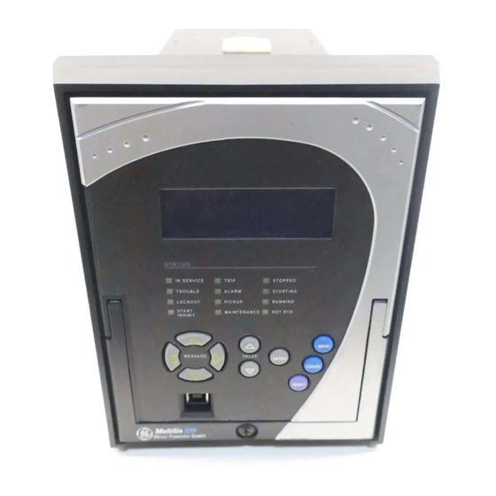
FRONT CONTROL PANEL INTERFACE CHAPTER 3: INTERFACES Front control panel interface Figure 3-1: 339 Motor Protection System front panel GE Multilin 339 Motor Protection System I SERVICE TRIP STOPPED TROUBLE ALARM STARTI G LOCKOUT PICKUP START MAI TE A CE... -
Page 69: Description
CHAPTER 3: INTERFACES FRONT CONTROL PANEL INTERFACE Figure 3-2: 339 Feeder Protection System Front Panel - Programmable LEDs GE Multilin 339 Motor Protection System IN SERVICE TROUBLE TRIP ALARM MENU ENTER ESCAPE RESET 896850A1.cdr Description The relay front panel provides an interface with a liquid crystal display, LED status indicators, control keys, and a USB program port. -
Page 70: Display
Any trip, alarm, or pickup is displayed immediately, automatically overriding the default message. Working with the The 339 display messages are organized into a Main Menu, pages, and sub-pages. There Keypad are four main menus labeled Actual Values, Quick Setup, Setpoints, and Maintenance. -
Page 71: Led Status Indicators - Front Panel With Non-Programmable Leds
If none of them is enabled, a normal reset can be used. • START INHIBIT: Red This LED turns "ON" when the Start Inhibit element is activated. The LED self-resets when the inhibit is no longer present. 339 MOTOR PROTECTION SYSTEM – INSTRUCTION MANUAL 3–5... - Page 72 This LED turns "ON" when either RTD Alarm or Trip has been activated. This LED is self- resetting when the fault is no longer present. Refer to M7 Testing for information on testing LED status indicators. NOTE: NOTE 3–6 339 MOTOR PROTECTION SYSTEM – INSTRUCTION MANUAL...
-
Page 73: Led Status Indicators - Front Panel With Programmable Leds
LED 7: Red/Orange/Green/Off - programmable source signal, type, and color • LED 8: Red/Orange/Green/Off - programmable source signal, type, and color Refer to M7 Testing for information on testing LED status indicators. NOTE: NOTE 339 MOTOR PROTECTION SYSTEM – INSTRUCTION MANUAL 3–7... -
Page 74: Relay Messages
SETPOINTS > S1 RELAY SETUP > FRONT PANEL > MESSAGE TIMEOUT timing out from the last pressed pushbutton. The following shows the format of a typical Target Message: Figure 3-6: Typical target message A4 TARGET MESSAGES CauseState: Operate ▼ Phase: 3–8 339 MOTOR PROTECTION SYSTEM – INSTRUCTION MANUAL... -
Page 75: Self-Test Errors
• Display the cause of major self-test failure. • Record the major self-test failure in the Event Recorder. Figure 3-7: Typical Self-test warning A4 TARGET MESSAGES UNIT FAILURE: Contact Factory: Error code:1 339 MOTOR PROTECTION SYSTEM – INSTRUCTION MANUAL 3–9... - Page 76 ALERT: RMIO validated; check CANBUS Mismatch communications communication. with the RMIO module are lost or interrupted. * Failure is logged after the detection of 5 consecutive failures - that is after 25 seconds 3–10 339 MOTOR PROTECTION SYSTEM – INSTRUCTION MANUAL...
-
Page 77: Flash Messages
This flash message is displayed in response to executing a command: ON, OFF, YES, NO, etc. INVALID PASSWORD This flash message appears upon an attempt to enter an incorrect password, as part of password security. 339 MOTOR PROTECTION SYSTEM – INSTRUCTION MANUAL 3–11... -
Page 78: Software Setup
Although settings can be entered manually using the control panel keys, a PC can be used to download setpoints through the communications port. The EnerVista 3 Series Setup software is available from GE Multilin to make this as convenient as possible. With EnerVista 3 Series Setup running, it is possible to: •... -
Page 79: Hardware And Software Requirements
The EnerVista 3 Series Setup software can run without a 339 connected to the computer. In this case, settings may be saved to a file for future use. If a 339 is connected to a PC and communications are enabled, the 339 can be programmed from the setting screens. In addition, measured values, status and trip messages can be displayed with the actual value screens. - Page 80 USB driver will be loaded into the computer, and the installation program will automatically create icons and add EnerVista 3 Series Setup software to the Windows start menu. The 339 device will be added to the list of installed IEDs in the EnerVista Launchpad window, as shown below. 3–14...
- Page 81 If you are going to communicate from your computer to the 339 Relay using the USB port: 10. Plug the USB cable into the USB port on the 339 Relay then into the USB port on your computer. 11. Launch EnerVista 3 Series Setup from LaunchPad.
-
Page 82: Upgrading The Software
(for USB communications) or to the RS485 terminals on the back of the device (for RS485 communications). This example demonstrates an USB connection. For RS485 communications, the GE Multilin F485 converter will be required. Refer to the F485 manual for additional details. To configure the relay for Ethernet communications, see Configuring Ethernet Communications below. -
Page 83: Using The Quick Connect Feature
As indicated by the window, the "Quick Connect" feature can quickly connect the EnerVista 3 Series Setup software to a 339 front port if the USB is selected in the interface drop-down list. Select "SR3 Relay" and press the Connect button. Ethernet can also be used as the interface for Quick Connect as shown above. -
Page 84: Configuring Ethernet Communications
SOFTWARE SETUP CHAPTER 3: INTERFACES The 339 Site Device has now been configured via the Quick Connect feature for either USB or Ethernet communications. Proceed to Connecting to the Relay below, to begin communications. Configuring Ethernet Before starting, verify that the Ethernet cable is properly connected to the RJ-45 Ethernet communications port. -
Page 85: Connecting To The Relay
Enter the IP address, slave address, and Modbus port values assigned to the 339 relay (from the S1 RELAY SETUP > COMMUNICATIONS > ETHERNET menu). Click the Read Order Code button to connect to the 339 and upload the order code. If a communications error occurs, ensure that the Ethernet communication values correspond to the relay setting values. -
Page 86: Working With Setpoints And Setpoint Files
Select the Setpoint > System Setup > Voltage Sensing menu item. Select the Bus VT Secondary setpoint by clicking anywhere in the parameter box. This will display three arrows: two to increment/decrement the value and another to launch the numerical keypad. 3–20 339 MOTOR PROTECTION SYSTEM – INSTRUCTION MANUAL... - Page 87 In the Setpoint > System Setup > Voltage Sensing dialog box, click on Save to save the values into the relay339 . Click YES to accept any changes and exit the window. Click Restore to retain previous values. Click Default to restore Default values. 339 MOTOR PROTECTION SYSTEM – INSTRUCTION MANUAL 3–21...
-
Page 88: Setting Programmable Leds
In the Setpoint > S1 Relay Setup > Front Panel dialog box, click Save to save the values into the 339 . Click YES to accept any changes. Click Restore to retain previous values. Click Default to restore Default values (all LEDs Off and colors Orange). -
Page 89: File Support
Control • Inputs/Outputs Factory default values are supplied and can be restored after any changes. The EnerVista 3 Series Setup displays relay setpoints with the same hierarchy as the front panel display. 339 MOTOR PROTECTION SYSTEM – INSTRUCTION MANUAL 3–23... -
Page 90: Downloading And Saving Setpoint Files
SOFTWARE SETUP CHAPTER 3: INTERFACES Downloading and Back up a copy of the in-service settings for each commissioned 339 unit, so as to revert saving setpoint files to the commissioned settings after inadvertent, unauthorized, or temporary setting changes are made, after the settings default due to firmware upgrade, or when the unit has to be replaced. -
Page 91: Creating A New Setpoint File
Select the file name and path to store the file, or select any displayed file name to replace an existing file. All 339 setpoint files should have the extension ‘SR3’ (for example, ‘feeder1.SR3’). Click OK to complete the process. Once this step is completed, the new file, with a complete path, will be added to the EnerVista 3 Series Setup software environment. -
Page 92: Upgrading Setpoint Files To A New Revision
It is often necessary to upgrade the revision for a previously saved setpoint file after the files to a new revision 339 firmware has been upgraded. This is illustrated in the following procedure: Establish communications with the 339 relay. Select the Maintenance > M1 Relay Info menu item and record the Firmware Revision. -
Page 93: Printing Setpoints And Actual Values
Establish communications with the desired 339 device. From the main window, select the Online > Print Device Information menu item The Print/Export Options dialog box will appear. Select Actual Values in the upper section and select either Include All Features (for a complete list) or Include Only Enabled Features (for a list of only those features which are currently used) in the filtering section and click OK. -
Page 94: Loading Setpoints From A File
Uninstalling files and The unit can be decommissioned by turning off the power to the unit and disconnecting the wires to it. Files can be cleared after uninstalling the EnerVista software or 339 device, clearing data for example to comply with data security regulations. On the computer, settings files can be identified by the .sr3 extension. -
Page 95: Upgrading Relay Firmware
Message,” indicating that it is in upload mode. While the file is being loaded into the 339 , a status box appears showing how much of the new firmware file has been transferred and the upgrade status. The entire transfer process takes approximately 10 minutes. - Page 96 SOFTWARE SETUP CHAPTER 3: INTERFACES The EnerVista 3 Series Setup software will notify the user when the 339 has finished loading the file. Carefully read any displayed messages and click OK to return the main screen. Cycling power to the relay is recommended after a firmware upgrade.
-
Page 97: Advanced Enervista 3 Series Setup Features
The user can load Trip Times from a CSV File • The screen above shows the model followed by 339 for viewing Flexcurves. Select Initialize to copy the trip times from the selected curve to the FlexCurve. 339 MOTOR PROTECTION SYSTEM – INSTRUCTION MANUAL... -
Page 98: Data Logger
To view a previously saved COMTRADE file, click the Open button and select the corresponding COMTRADE file. To view the datalog, click the Launch Viewer button. A detailed Datalog window will appear as shown below. 3–32 339 MOTOR PROTECTION SYSTEM – INSTRUCTION MANUAL... - Page 99 The method of customizing the datalog view is the same as the Waveform Capture described below. The datalog can be set to capture another buffer by clicking on Run (when Continuous mode is enabled), or by clicking on Release (when Continuous mode is disabled). 339 MOTOR PROTECTION SYSTEM – INSTRUCTION MANUAL 3–33...
-
Page 100: Motor Start Data Logger
CHAPTER 3: INTERFACES Motor start data When a motor start status is detected by the 339 relay, a start data logger is triggered and logger begins to sample and record the following parameters at a rate of 1 sample every 200ms: •... -
Page 101: Transient Recorder (Waveform Capture)
• Click on Trigger Waveform to trigger a waveform capture. Waveform file numbering starts with the number zero in the 339 , so that the maximum trigger number will always be one less than the total number of triggers available. - Page 102 Cursor complete path click and drag the cursor to the trigger. lines are identified (if saved). new position. by their colors. 3–36 339 MOTOR PROTECTION SYSTEM – INSTRUCTION MANUAL...
- Page 103 The Waveform Capture window will reappear based on the selected graph attributes. To view a vector graph of the quantities contained in the waveform capture, press the Vector Display button to display the following window: 339 MOTOR PROTECTION SYSTEM – INSTRUCTION MANUAL 3–37...
-
Page 104: Protection Summary
• view the enable/disable status of Control Elements • navigate to the respected Protection Element screen on a button click. An example of the Protection Summary screen follows: 3–38 339 MOTOR PROTECTION SYSTEM – INSTRUCTION MANUAL... - Page 105 CHAPTER 3: INTERFACES SOFTWARE SETUP 339 MOTOR PROTECTION SYSTEM – INSTRUCTION MANUAL 3–39...
-
Page 106: Password Security
CHAPTER 3: INTERFACES Password security Password security is an optional feature of the 339 which can be setup using the EnerVista 3 Series Setup software. The password system has been designed to facilitate a hierarchy for centralized management. This is accomplished through a Master level access password which can be used for resetting lower level access passwords and higher level privileged operations. - Page 107 The access level turns off after a period of 5 minutes of inactivity, if control power is cycled, or if the user enters an incorrect password. 339 MOTOR PROTECTION SYSTEM – INSTRUCTION MANUAL 3–41...
- Page 108 SOFTWARE SETUP CHAPTER 3: INTERFACES 3–42 339 MOTOR PROTECTION SYSTEM – INSTRUCTION MANUAL...
-
Page 109: Actual Values
All measured values, the status of digital inputs and outputs, and fault analysis information are accessed in Actual Values mode. Actual value messages are organized into logical groups for easy reference as shown below. 339 MOTOR PROTECTION SYSTEM – INSTRUCTION MANUAL 4–1... - Page 110 GOOSE STATUS GOOSE HDR STATUS A3 RECORDS RTD TEMP SUMMARY EVENT RECORDS TRANSIENT RECORDS FAULT REPORT LEARNED DATA LEARNED DATA REC CLEAR EVENT REC CLEAR TRANST REC CLEAR LEARNED DATA CLEAR FAULT REPORT 4–2 339 MOTOR PROTECTION SYSTEM – INSTRUCTION MANUAL...
-
Page 111: A1 Status
THERMAL INHIBIT Time in seconds left until the Thermal Start Inhibit expires. Has a value of zero if this feature is set to OFF, or if the time has expired. 339 MOTOR PROTECTION SYSTEM – INSTRUCTION MANUAL 4–3... - Page 112 A thermal overload lockout will occur after a thermal overload trip so that the user cannot start the motor until the TCU drops to 15%. Following a thermal overload trip, this value indicates how long it will take for the 339 relay TCU to decrease from the current value to 15%.
-
Page 113: Clock
CONTACT INPUT 3 to 10 Range: Off, On Message displays the state of the contact input. The message “ON” indicates that the contact input is energized, and message “OFF” indicates a de-energized contact. 339 MOTOR PROTECTION SYSTEM – INSTRUCTION MANUAL 4–5... -
Page 114: Output Relays
LOGIC ELEMENT 1 to 16 Range: Off, On The state “ON” or “OFF” for each logic element depends on its programmed logic: triggering inputs, blocking inputs, plus any pickup, and/or reset time delay. 4–6 339 MOTOR PROTECTION SYSTEM – INSTRUCTION MANUAL... -
Page 115: Virtual Inputs
ACTUAL VALUES > A1 STATUS > C. INPUTS SUMMARY C. INPUTS SUMMARY CI#6 CI#7 CI#3 CI#8 CI#4 CI#9 CI#5 CI#10 The display shows a summary of the states of all contact inputs. 339 MOTOR PROTECTION SYSTEM – INSTRUCTION MANUAL 4–7... -
Page 116: Output Relays Summary
Output relay #7 is the Critical Failure relay, used to indicate the correct functioning of the NOTE: 339 relay. This output relay shows the status "ON" when the 339 relay is powered up and set to "Ready" and no self-test alarms are active, under SETPOINTS >... -
Page 117: Rtd Temp Summary
Empty: there is no CID file in the SCL/notvalidated directory. RTD temp summary PATH: ACTUAL VALUES > A1 STATUS > RTD TEMP SUMMARY RTD TEMP SUMMARY This display shows a summary of the states of all RTDs. 339 MOTOR PROTECTION SYSTEM – INSTRUCTION MANUAL 4–9... -
Page 118: A2 Metering
SENS GND CURRENT is shown when the GROUND CT TYPE is set to "50:0.025". Voltage Path: ACTUAL VALUES > A2 METERING > VOLTAGE AN VOLTAGE 0 V 0 Range: 0 to 65535 V AN VOLTAGE ANGLE 0 V 0 Range: 0 to 65535 V 4–10 339 MOTOR PROTECTION SYSTEM – INSTRUCTION MANUAL... - Page 119 POS SEQ VOLTAGE 0 V 0 Range: 0 to 65535 V POS SEQ VOLTAGE ANGLE 0 V 0 Range: 0 to 65535 V NEG SEQ VOLTAGE 0 V 0 Range: 0 to 65535 V 339 MOTOR PROTECTION SYSTEM – INSTRUCTION MANUAL 4–11...
-
Page 120: Power
Range: 0.000 to 50000.000 MWh NEGATIVE WATTHOUR 0.000 MWh Range: 0.000 to 50000.000 MWh POSITIVE VARHOUR 0.000 MVarh Range: 0.000 to 50000.000 MVarh NEGATIVE VARHOUR 0.000 MVarh Range: 0.000 to 50000.000 MVarh 4–12 339 MOTOR PROTECTION SYSTEM – INSTRUCTION MANUAL... -
Page 121: Current Demand
REAL PWR DEMAND Range: 0.0 to 100000.0 kW MAX REAL PWR DMD Range: 0.0 to 100000.0 kW REACTIVE PWR DMD Range: 0.0 to 100000.0 kVar MAX REACTIVE PWR DMD Range: 0.0 to 100000.0 kVar 339 MOTOR PROTECTION SYSTEM – INSTRUCTION MANUAL 4–13... -
Page 122: Rtd Temperature
When set to "YES," pressing the ENTER key will clear all current demand data. Clear power demand Path: ACTUAL VALUES > A2 METERING > CLEAR POWER DEMAND CLEAR ENERGY Range: No, Yes When set to "YES," pressing the ENTER key will clear all power data. 4–14 339 MOTOR PROTECTION SYSTEM – INSTRUCTION MANUAL... -
Page 123: A3 Records
A3 RECORDS A3 Records The 339 has an event recorder which runs continuously. All event records are stored in memory such that information is maintained for up to 3 days even after losing relay control power. The events are displayed from newest to oldest event. Each event has a... - Page 124 Block Events BLOCK: These are events that occur upon activation of any block signal. Setting Date/Time Events GENERAL: These are events that occur upon changing the date or time in the relay. 4–16 339 MOTOR PROTECTION SYSTEM – INSTRUCTION MANUAL...
-
Page 125: Transient Records
PH A CURRENT 0.0 A 0 PH B CURRENT 0.0 A 0 PH C CURRENT 0.0 A 0 GND CURRENT 0.0 A 0 NTRL CURRENT 0.0 A 0 SENS GND CURRENT 0.00 A 0 339 MOTOR PROTECTION SYSTEM – INSTRUCTION MANUAL 4–17... -
Page 126: Learned Data
60.00 Hz Learned data The 339 measures and records individual data records, as indicated below, all from actual motor operation. The latest individual data record "set" can be viewed using the Learned Data feature on the relay. The data, when input cumulatively to the Learned Data Recorder (see below) can be used to evaluate changes/trends over time. - Page 127 RTD temperature value is greater than the RDT maximum temperature already stored, the RDT maximum temperature is set to this latest captured RTD temperature value. The RTD maximum temperature values are maintained in non-volatile memory to carry over a relay power interruption. 339 MOTOR PROTECTION SYSTEM – INSTRUCTION MANUAL 4–19...
-
Page 128: Learned Data Recorder
When set to "Yes," pressing the ENTER key will clear all transient records. Clear fault report PATH: ACTUAL VALUES > A3 RECORDS > CLEAR FAULT REPORT CLEAR Range: No, Yes When set to "Yes," pressing the ENTER key will clear all fault reports. 4–20 339 MOTOR PROTECTION SYSTEM – INSTRUCTION MANUAL... -
Page 129: A4 Target Messages
A4 TARGET MESSAGES Short Circuit Trip STATE: PKP After the 200 ms time delay expires, the display shows the following message only: A4 TARGET MESSAGES Short Circuit Trip STATE: OP Example 2: 339 MOTOR PROTECTION SYSTEM – INSTRUCTION MANUAL 4–21... - Page 130 SHORT CIRCUIT PICKUP = 1.00 x CT • SHORT CIRCUIT DELAY = 0.20 s When current greater than the Short Circuit pickup level is applied, the 339 display shows the following target message: A4 TARGET MESSAGES Ph Short Circuit Alarm...
-
Page 131: Quick Setup - Front Control Panel
Quick setup - Front control panel The “Quick Setup” utility is part of the 339 relay main menu, and can be used for quick and easy programming. Power system parameters, and settings for some simple over-current elements can be easily set. - Page 132 MECHANICAL JAM FUNC Range: Disabled, Enabled Default: Disabled U/CURR TRIP FUNC Range: Disabled, Enabled Default: Disabled GROUND TRIP FUNC Range: Disabled, Enabled Default: Disabled PH UV1 FUNCTION Range: Disabled, Enabled Default: Disabled 5–2 339 MOTOR PROTECTION SYSTEM – INSTRUCTION MANUAL...
- Page 133 The settings changed using the Quick Setup menu, are available for review and NOTE: modification by navigating through S1 RELAY SETUP, S2 SYSTEM SETUP and S3 PROTECTION in the SETPOINTS main menu. NOTE 339 MOTOR PROTECTION SYSTEM – INSTRUCTION MANUAL 5–3...
- Page 134 QUICK SETUP SETTINGS CHAPTER 5: QUICK SETUP - FRONT CONTROL PANEL 5–4 339 MOTOR PROTECTION SYSTEM – INSTRUCTION MANUAL...
- Page 135 Setpoints Setpoints Main Menu The 339 has a considerable number of programmable setpoints, all of which make the relay extremely flexible. These setpoints have been grouped into a variety of pages and subpages as shown below. Each setpoints menu has a section that describes in detail the setpoints found on that menu.
-
Page 136: Setpoints Setpoints Main Menu
PHASE REVERSAL OUTPUT RELAYS VT FUSE FAILURE VIRTUAL INPUTS ACCELERATION RTD PROTECTION 896757A2.cdr TWO SPEED MOTOR NTRL DIR DIR POWER 1 DIR POWER 2 POS SEQ UV 1 POS SEQ UV 2 6–2 339 MOTOR PROTECTION SYSTEM – INSTRUCTION MANUAL... -
Page 137: Setpoint Entry Methods
Files can be stored and downloaded for fast, error free entry when a computer is used. To facilitate this process, the GE EnerVista CD with the EnerVista 3 Series Setup software is supplied with the relay. -
Page 138: Logic Diagrams
LED Indicators: Shown as the following schematic symbol, □. The exact wording of • the front panel label identifies the indicator. • Logic: Described with basic logic gates (AND, OR, XOR, NAND, NOR). The inverter (logical NOT), is shown as a circle: ○. 6–4 339 MOTOR PROTECTION SYSTEM – INSTRUCTION MANUAL... -
Page 139: Setting Text Abbreviations
Hz: Hertz • MAX: maximum • MIN: minimum • SEC, s: seconds • UV: undervoltage • OV: overvoltage • VT: voltage transformer • Ctrl: control • Hr & hr: hour • O/L: overload 339 MOTOR PROTECTION SYSTEM – INSTRUCTION MANUAL 6–5... -
Page 140: S1 Relay Setup
896764A1.cdr Clock The 339 relay has an internal real time clock that performs time stamping via IRIG-B for various features such as the event and transient recorders. This time stamping is available with the IRIG-B signal connected to the relay terminals and set to “Enabled”. When an IRIG- B device is connected to the relay terminals, the relay detects the DC shift or the Amplitude Modulated signal automatically. - Page 141 Weekday defining the end of the Daylight Saving time. The clock has a super-capacitor back-up, so that time, date, and events will be kept for up to 3 days in cases of loss of relay control power. 339 MOTOR PROTECTION SYSTEM – INSTRUCTION MANUAL 6–7...
-
Page 142: Password Security
When “Disabled” is selected for this setting, SNTP time synchronization is disabled. SNTP PORT: Range: 0 to 65535 Default: 0 This setting configures the port that 339 .is using. SNTP SERVER IP ADR: Range: Standard IP Address format Default: 000.000.000.000 This setting must be set to the SNTP/NTP server IP address. -
Page 143: Access Passwords
The remote user has the Overwrite Local Passwords setpoint set to NO • The local user knows the current local password. For more details on the Password Security feature, refer to Chapter 3. 339 MOTOR PROTECTION SYSTEM – INSTRUCTION MANUAL 6–9... - Page 144 Disabled by default. Changing the value of "PSWD FOR RESET KEY" requires the Master Password. If the Master Password has already been provided by the current user, further password confirmation is not required for this setpoint (the 5 minutes of inactivity rule does not apply). 6–10 339 MOTOR PROTECTION SYSTEM – INSTRUCTION MANUAL...
-
Page 145: Communications
897766A2.cdr RS485 interface The 339 is equipped with one serial RS485 communication port. The RS485 port has settings for baud rate and parity. It is important that these parameters agree with the settings used on the computer or other equipment that is connected to these ports. This port may be connected to a computer running the EnerVista 3 Series Setup software. -
Page 146: Modbus
NOTE Modbus The Modicon Modbus protocol is supported by the 339 . Modbus is available via the RS485 serial link (Modbus RTU). The 339 always acts as a slave device, meaning that it never initiates communications; it only listens and responds to requests issued by a master device. -
Page 147: Iec 60870-5-103 Serial Communication
Please refer to the 3 Series Communications Guide for details on how to set up the DNP protocol. For a complete list of Binary inputs, see Format Code FC134B in the 3 Series Communications Guide. Note that the format codes differ for each relay model. 339 MOTOR PROTECTION SYSTEM – INSTRUCTION MANUAL 6–13... -
Page 148: Series Iec 61850 Goose Details
(one level of nesting) and all the standard data types. GOOSE settings changes will take effect only after the 339 is re-booted. One setting is available to Enable/Disable both Transmission and Reception. It is possible to change this setting from the Front Panel of the relay. -
Page 149: Event Recorder
When set to “Enabled”, the event recorder will record the event, when a contact input changes its state. LOGIC ELEMENT Range: Disabled, Enabled Default: Enabled When set to “Enabled”, the event recorder records the events, which occur upon state change of any programmed remote input. 339 MOTOR PROTECTION SYSTEM – INSTRUCTION MANUAL 6–15... -
Page 150: Transient Recorder
This setting indicates the location of the trigger with respect to the selected length of record. For example at 20% selected trigger position, the length of each record will be split on 20% pre-trigger data, and 80% post-trigger data. 6–16 339 MOTOR PROTECTION SYSTEM – INSTRUCTION MANUAL... - Page 151 Default: Off Selection of input or logic element from the settings range enables triggering input for the recorder. A record will be triggered if the status of the selected input changes to “On”. 339 MOTOR PROTECTION SYSTEM – INSTRUCTION MANUAL 6–17...
-
Page 152: Fault Report
CHAPTER 6: SETPOINTS Fault report The 339 relay has a Fault Report which captures measured analog signals at the time of the trip. The Fault Report stores only the last recorded values in relay's non-volatile memory. The Fault Report has two configurable setpoints, "FAULT TRIGGER" and "DELAY OTHER TRIGGERS". -
Page 153: Datalogger
Selects the data to be stored for each sample of the data log channel. Sources and Defaults for Channels 2 to 10 are the same as those for Channel 1. NOTE: NOTE 339 MOTOR PROTECTION SYSTEM – INSTRUCTION MANUAL 6–19... -
Page 154: Front Panel With Non-Programmable Leds
Self-Reset or Latched. The LED color for LED5 to LED8 can also be programmed. By default the programmable LEDs are all Off, with no source selected. The LEDs on the relay front panel are ordered as shown: 6–20 339 MOTOR PROTECTION SYSTEM – INSTRUCTION MANUAL... - Page 155 Range: Any operand from the list of logic operands Default: Off Selects the signal source of programmable LED 1 through 8. LED1(8) TYPE Range: Self-reset, Latched Default: Self-reset Selects the type of programmable LED 1 through 8. 339 MOTOR PROTECTION SYSTEM – INSTRUCTION MANUAL 6–21...
-
Page 156: Installation
Range: Yes, No Default: No The 339 relay allows remote metering and programming for up to 12 RTDs via a CANBUS-based RMIO module. Refer to Chapter 2 - RMIO Installation for details. The 339 will automatically detect the installed RMIO cards when the relay is booted, at which 6–22... -
Page 157: Preset Statistics
CHAPTER 6: SETPOINTS S1 RELAY SETUP time the user must send a YES command to validate the RMIO. Otherwise the 339 relay will issue a RMIO MISMATCH self-test error. It is recommended to power cycle the 339 after validating the RMIO module. -
Page 158: S2 System Setup
Range: 1 A or 5 A Default: 5 A Configurable 1 A or 5 A secondary, available with Phase Current option ‘P0’ installed. Enter the rated phase CT secondary current of the three-phase current transformers. 6–24 339 MOTOR PROTECTION SYSTEM – INSTRUCTION MANUAL... - Page 159 Core Balance CT current or the fourth CT input current. The 339 has an isolating transformer with 1A or 5A Ground CT terminals and CBCT 50:0.025 terminals. Only one ground CT input tap should be used on a given unit. There are no internal ground connections on the ground current inputs.
-
Page 160: Voltage Sensing
Range: Wye, Delta Default: Wye The 339 provides three-phase VT inputs. Select “Wye” connection, if phase-neutral voltages are wired to the relay VT terminals. Select “Delta” connection, if phase-phase voltages from Delta VT are connected to the three-phase VT terminals. See the VT connections per the Typical Wiring Diagram in Chapter 2. -
Page 161: Motor
The status of this switch is used by the relay to ensure that in low speed operation the relay maintains running status when current draw is very low. Use a form- a (normally open) auxiliary contact of the low speed (speed 1) contactor. 339 MOTOR PROTECTION SYSTEM – INSTRUCTION MANUAL 6–27... -
Page 162: Switching Device
In some cases, the fault current can exceed the current which the contactor is rated to supervision interrupt. If such a condition has been detected, the 339 blocks the operation of output relay 1 "Trip" and operates a selected auxiliary output relay. The same auxiliary output relay must be wired to the upstream switching device (usually a breaker) that is rated to interrupt the fault current. - Page 163 Logic element 1 and Logic element 2 configuration Logic Element 1 setup for blocking TRIP output relay for 1 sec: Logic Element 2 setup used to energize Aux. relay 6 and trip upstream breaker: 339 MOTOR PROTECTION SYSTEM – INSTRUCTION MANUAL 6–29...
-
Page 164: Flexcurves
Output Relay #1 (TRIP) configuration Output Relay 1 (TRIP) blocked by LE1: FlexCurves There are two user-programmable FlexCurves™ available with the 339 system, labeled A and B. For details on FlexCurves please refer to S3 Protection/Thermal Protection in this manual. - Page 165 CHAPTER 6: SETPOINTS S2 SYSTEM SETUP 339 MOTOR PROTECTION SYSTEM – INSTRUCTION MANUAL 6–31...
-
Page 166: Vfd
The VFD FUNCTION setting must be enabled in order to ensure proper performance of the 339 relay for motor applications with VFD. In motor applications where the VFD can be bypassed, status of the bypass switch must be configured as a selected input under setpoint BYPASS SWITCH. - Page 167 VFD Not Bypassed operand is de-asserted. Voltage inputs to the 339 motor protection relay are normally measured at the busbar side of the VFD where they are substantially sinusoidal. Since the output phase voltages from a VFD are not sinusoidal and are distorted due to harmonics generated by the VFD, blocking the voltage elements via the Block setting using the “VFD Not Bypassed”...
-
Page 168: S3 Protection
DIRECTIONAL POWER 2 896758A4. cdr Motor Thermal Model The primary protective function of the 339 motor relay is motor thermal protection. The 339 thermal protection consists of seven key elements: • Start Protection - accounts for the rapid heating that occurs during starting •... -
Page 169: Total Capacity Used Register (Tcu)
= the period in seconds corresponding to the nominal power system frequency. system The 339 thermal protection addresses the two distinct parts of the thermal limit curve: the motor starting limit, and the running limit. The start protection determines Time to Trip during motor starting, and the thermal overload curve determines Time to Trip during motor running. -
Page 170: Start Protection
If the motor starting times are well within the safe stall times, it is recommended that the 339 standard overload curve be used. The standard overload curves are a series of 15 curves, each a multiple from 1 to 15 of a common curve shape based on typical motor thermal limit curves. - Page 171 CHAPTER 6: SETPOINTS S3 PROTECTION Figure 6-15: Standard Overload Curve Trip Times STANDARD MOTOR CURVES 8 x FLA 100000 10000 1000 1.00 0.10 1.00 896804A1.CDR Multiples of FLA 339 MOTOR PROTECTION SYSTEM – INSTRUCTION MANUAL 6–37...
- Page 172 7.50 1.58 3.16 4.75 6.33 7.91 9.49 11.0 12.6 14.2 15.8 17.4 18.9 20.5 22.1 23.7 8.00 1.39 2.78 4.16 5.55 6.94 8.33 9.71 11.1 12.4 13.8 15.2 16.6 18.0 19.4 20.8 6–38 339 MOTOR PROTECTION SYSTEM – INSTRUCTION MANUAL...
- Page 173 1.39 2.78 4.16 5.55 6.94 8.33 9.71 11.1 12.4 13.8 15.2 16.6 18.0 19.4 20.8 Table 6-2: Conversion Between NEMA Curves and 339 Curve Multiplier NEMA Curve Class 10 Class 15 Class 20 Class 30 339 Curve Multiplier UNBALANCE BIASING Unbalanced phase currents, that is to say negative sequence currents, cause rotor heating in addition to the normal heating caused by positive sequence currents.
- Page 174 6, 12, 18, 24, and 30% respectively. Based on these assumptions, the derating resulting from this relay’s unbalance biasing for different values of k is as illustrated in the GE Multilin curve below. Note that the curve for k = 8 is almost identical to the NEMA derating curve.
- Page 175 THERMAL CAPACITY USED is forced to 100%. At values between the maximum and minimum, the THERMAL CAPACITY USED created by the overload curve is compared to the RTD Bias Thermal Capacity Used determined by the hottest stator RTD temperature. 339 MOTOR PROTECTION SYSTEM – INSTRUCTION MANUAL 6–41...
- Page 176 (starting, running). The time constant is, in each case, the time in minutes for the motor’s temperature to cool by 63% of the difference between the initial temperature and ambient temperature. Motor cooling is calculated as: Eq. 13 where: 6–42 339 MOTOR PROTECTION SYSTEM – INSTRUCTION MANUAL...
- Page 177 Constant Stopped setting), the lockout is replaced with a trip that can be manually reset, or alternatively the condition is fully reset, allowing immediate re-start. THERMAL CAPACITY ALARM A Thermal Capacity Alarm will occur when the Thermal Capacity rises above the programmed THERMAL ALARM PKP level. 339 MOTOR PROTECTION SYSTEM – INSTRUCTION MANUAL 6–43...
-
Page 178: Flexcurves
I represents the input current, I represents the value of the pickup pickup current setting, T represents the FlexCurve™ time in seconds. flex Figure 6-19: Flexcurve™ configuration settings The following settings are available for each custom Flexcurve™. 6–44 339 MOTOR PROTECTION SYSTEM – INSTRUCTION MANUAL... -
Page 179: Thermal Protection Setpoints
SAFE STALL T COLD Range: 1.0 to 600.0 sec in steps of 0.1 sec Default: 10.0 sec This setting is given as the Safe Stall Time Cold. 339 MOTOR PROTECTION SYSTEM – INSTRUCTION MANUAL 6–45... - Page 180 Range: Standard, FlexCurve Default: Standard When FlexCurve is selected, the 339 relay used motor speed indication to apply FlexCurve A or FlexCurve B. Flex curve A is active when the motor is running at low speed. Flex curve B is active when the motor is running at high speed. If two-speed function is not deployed, only FlexCurve A is active.
- Page 181 This trip must be reset by the control panel, a remote contact, or a communication command, before the motor can be restarted. OUTPUT RELAY X For details see Common setpoints. BLOCK 1 to 3 For details see Common setpoints. 339 MOTOR PROTECTION SYSTEM – INSTRUCTION MANUAL 6–47...
- Page 182 S3 PROTECTION CHAPTER 6: SETPOINTS Figure 6-20: Thermal Protection logic diagram 6–48 339 MOTOR PROTECTION SYSTEM – INSTRUCTION MANUAL...
-
Page 183: Short Circuit (50P)
A second independent Short Circuit protection element is provided for High Speed. If two- speed functionality is enabled, the 339 relay relies on the motor speed indication to switch the Short Circuit settings as per the motor running speed, so the main Short Circuit is only active when the motor is running at low speed, and the High Speed Short Circuit is only active when the motor is running at high speed. - Page 184 S3 PROTECTION CHAPTER 6: SETPOINTS Figure 6-21: Short Circuit logic diagram 6–50 339 MOTOR PROTECTION SYSTEM – INSTRUCTION MANUAL...
-
Page 185: Mechanical Jam (51R)
The Mechanical Jam is armed as long as the motor status is not STARTING. When two- speed functionality is deployed, the 339 will block Mechanical Jam Protection during the acceleration time from Low Speed to High Speed until the motor current has dropped below overload pickup level. - Page 186 S3 PROTECTION CHAPTER 6: SETPOINTS Figure 6-22: Mechanical Jam logic diagram 6–52 339 MOTOR PROTECTION SYSTEM – INSTRUCTION MANUAL...
-
Page 187: Undercurrent (37)
A second independent Undercurrent Protection element is provided for High Speed. If two- speed functionality is enabled, the 339 relay relies on the motor speed indication to switch the undercurrent settings as per the motor running speed, so the main Undercurrent... - Page 188 To select any assignable output relays to operate upon the Undercurrent Alarm operation, assign the Logic Operand "UNDERCURRENT ALARM OP" or "Any Alarm OP" to a Logic Element. BLOCK 1 to 3 For details see Common setpoints. 6–54 339 MOTOR PROTECTION SYSTEM – INSTRUCTION MANUAL...
- Page 189 CHAPTER 6: SETPOINTS S3 PROTECTION Figure 6-23: Undercurrent logic diagram 339 MOTOR PROTECTION SYSTEM – INSTRUCTION MANUAL 6–55...
-
Page 190: Current Unbalance (46)
However, the current unbalance protection can detect this condition and alarm or trip before the motor has heated substantially. For the 339 relay, unbalance is defined as the ratio of negative-sequence to positive- sequence current, Eq. 15 if the motor is operating at a load (I ) greater than or equal to FLA. - Page 191 Current Unbalance element. Unbalance minimum time must be set in order to prevent false operation of the element 339 MOTOR PROTECTION SYSTEM – INSTRUCTION MANUAL 6–57...
- Page 192 To select any assignable output relays to operate upon the Unbalance Alarm operation, assign the Logic Operand "UNBALANCE ALARM OP" or "Any Alarm OP" to a Logic Element. BLOCK 1 to 3 For details see Common setpoints. 6–58 339 MOTOR PROTECTION SYSTEM – INSTRUCTION MANUAL...
- Page 193 CHAPTER 6: SETPOINTS S3 PROTECTION Figure 6-25: Current Unbalance logic diagram 339 MOTOR PROTECTION SYSTEM – INSTRUCTION MANUAL 6–59...
-
Page 194: Load Increase Alarm (50L)
ANY ALARM PKP SETTINGS BLOCK 1 OFF = 0 TARGET MESSAGE BLOCK 2 Load Incr Alarm OFF = 0 State: Operate BLOCK 3 OFF = 0 Load Incr Alarm State: Pickup 896818.cdr 6–60 339 MOTOR PROTECTION SYSTEM – INSTRUCTION MANUAL... -
Page 195: Ground Fault (50G/Sg)
Ground fault protection provides early detection of such leakage current, so that the motor can be taken off line in time to limit motor damage. The 339 has one Ground/Sensitive Ground Fault protection. Depending on the setting , the current measured by this SYSTEM SETUP >... - Page 196 To select any assignable output relays to operate upon the Ground Fault Alarm operation, assign the Logic Operand "GROUND FAULT ALARM OP" or "Any Alarm OP" to a Logic Element. BLOCK 1 to 3 For details see Common setpoints. 6–62 339 MOTOR PROTECTION SYSTEM – INSTRUCTION MANUAL...
- Page 197 CHAPTER 6: SETPOINTS S3 PROTECTION Figure 6-27: Ground Fault logic diagram 339 MOTOR PROTECTION SYSTEM – INSTRUCTION MANUAL 6–63...
-
Page 198: Neutral Instantaneous Overcurrent (50N)
OUTPUT RELAY X For details see Common setpoints. BLOCK 1 to 3 For details see Common setpoints. 6–64 339 MOTOR PROTECTION SYSTEM – INSTRUCTION MANUAL... - Page 199 CHAPTER 6: SETPOINTS S3 PROTECTION Figure 6-28: Neutral Instantaneous Overcurrent logic diagram 339 MOTOR PROTECTION SYSTEM – INSTRUCTION MANUAL 6–65...
-
Page 200: Time Overcurrent Curves
The Linear selection can be used where the relay must coordinate with 6–66 339 MOTOR PROTECTION SYSTEM – INSTRUCTION MANUAL... - Page 201 0.246 0.226 8.568 3.531 1.508 1.025 0.814 0.689 0.604 0.541 0.492 0.452 17.137 7.062 3.016 2.051 1.627 1.378 1.208 1.082 0.983 0.904 25.705 10.594 4.524 3.076 2.441 2.067 1.812 1.622 1.475 1.356 339 MOTOR PROTECTION SYSTEM – INSTRUCTION MANUAL 6–67...
- Page 202 10.800 5.400 2.700 1.800 1.350 1.080 0.900 0.771 0.675 0.600 0.60 16.200 8.100 4.050 2.700 2.025 1.620 1.350 1.157 1.013 0.900 0.80 21.600 10.800 5.400 3.600 2.700 2.160 1.800 1.543 1.350 1.200 6–68 339 MOTOR PROTECTION SYSTEM – INSTRUCTION MANUAL...
- Page 203 Eq. 19 where: T = trip time (seconds), M = multiplier setpoint, I = input current, I = pickup current setpoint, A to E = constants. Table 6-7: GE Type IAC Inverse Curve Constants IAC Curve Shape IAC Extreme Inverse 0.0040 0.6379...
-
Page 204: Phase Timed Overcurrent (51P)
Chapter 3 - Working with the Keypad. PATH: SETPOINTS > S3 PROTECTION > PHASE TOC PH TOC FUNCTION Range: Disabled, Latched Alarm, Alarm, Trip Default: Disabled For details see Common setpoints. 6–70 339 MOTOR PROTECTION SYSTEM – INSTRUCTION MANUAL... - Page 205 The “Timed” reset method can be used where the relay must coordinate with electromechanical relays. OUTPUT RELAY X For details see Common setpoints. BLOCK 1/2/3 For details see Common setpoints. 339 MOTOR PROTECTION SYSTEM – INSTRUCTION MANUAL 6–71...
- Page 206 S3 PROTECTION CHAPTER 6: SETPOINTS Figure 6-29: Phase time overcurrent protection logic diagram 6–72 339 MOTOR PROTECTION SYSTEM – INSTRUCTION MANUAL...
-
Page 207: Neutral Timed Overcurrent (51N)
The “Timed” reset method can be used where the relay must coordinate with electromechanical relays. 339 MOTOR PROTECTION SYSTEM – INSTRUCTION MANUAL 6–73... - Page 208 A special case is considered when fault direction is undefined. Then “BLK OC DIR UN” setting in Neutral Directional defines the fault direction. OUTPUT RELAY X For details see Common setpoints. BLOCK 1/2/3 For details see Common setpoints. 6–74 339 MOTOR PROTECTION SYSTEM – INSTRUCTION MANUAL...
- Page 209 CHAPTER 6: SETPOINTS S3 PROTECTION Figure 6-30: Neutral Timed Overcurrent Protection: Logic Diagram 339 MOTOR PROTECTION SYSTEM – INSTRUCTION MANUAL 6–75...
-
Page 210: Phase Undervoltage (27P)
Chapter 3 - Working with the Keypad. PATH: SETPOINTS > S3 PROTECTION > PHASE UV1(2) PH UV FUNCTION Range: Disabled, Alarm, Latched Alarm, Trip Default: Disabled For details see Common setpoints. 6–76 339 MOTOR PROTECTION SYSTEM – INSTRUCTION MANUAL... - Page 211 Default: 0.30 x VT The minimum operating voltage level is programmable to prevent undesired UV operation before voltage becomes available. OUTPUT RELAY X For details see Common setpoints. BLOCK 1/2/3 For details see Common setpoints. 339 MOTOR PROTECTION SYSTEM – INSTRUCTION MANUAL 6–77...
- Page 212 S3 PROTECTION CHAPTER 6: SETPOINTS Figure 6-32: Phase Undervoltage logic diagram 6–78 339 MOTOR PROTECTION SYSTEM – INSTRUCTION MANUAL...
-
Page 213: Phase Overvoltage (59P)
Therefore, the overvoltage element may be useful for protecting the motor in the event of a sustained overvoltage condition. The 339 provides 2 Phase Overvoltage elements. Each element can be set to either cause a trip or generate an alarm when the input voltage exceeds the pickup level for a specified time delay. - Page 214 S3 PROTECTION CHAPTER 6: SETPOINTS Figure 6-33: Phase Overvoltage logic diagram 6–80 339 MOTOR PROTECTION SYSTEM – INSTRUCTION MANUAL...
-
Page 215: Negative Sequence Overvoltage (59_2)
Range: 0.00 to 600.00 sec in steps of 0.01 sec Default: 2.00 s This setting specifies the time delay before OV operation. OUTPUT RELAY X For details see Common setpoints. BLOCK 1/2/3 For details see Common setpoints. 339 MOTOR PROTECTION SYSTEM – INSTRUCTION MANUAL 6–81... - Page 216 S3 PROTECTION CHAPTER 6: SETPOINTS Figure 6-34: Negative Sequence Overvoltage logic diagram 6–82 339 MOTOR PROTECTION SYSTEM – INSTRUCTION MANUAL...
-
Page 217: Positive Sequence Undervoltage (27_1)
The following path is available using the keypad. For instructions on how to use the keypad, please refer to Chapter 3 - Working with the Keypad. PATH: SETPOINTS > S3 PROTECTION > POSITIVE SEQ UV 339 MOTOR PROTECTION SYSTEM – INSTRUCTION MANUAL 6–83... - Page 218 DELTA, the user must set the Min Voltage value SQRT(3) times higher than expected in order to compensate. OUTPUT RELAY X For details see Common setpoints. BLOCK 1/2/3 For details see Common setpoints. 6–84 339 MOTOR PROTECTION SYSTEM – INSTRUCTION MANUAL...
- Page 219 CHAPTER 6: SETPOINTS S3 PROTECTION Figure 6-36: Positive sequence undervoltage logic diagram 339 MOTOR PROTECTION SYSTEM – INSTRUCTION MANUAL 6–85...
-
Page 220: Underfrequency (81U)
CHAPTER 6: SETPOINTS Underfrequency (81U) The 339 provides 2 Underfrequency Protection elements. Each element can be set to either cause a trip or generate an alarm when the frequency of the input voltage (wye- connected VT: VAN; delta-connected VT: VAB) drops below the pickup level for a specified time delay. - Page 221 CHAPTER 6: SETPOINTS S3 PROTECTION Figure 6-37: Underfrequency logic diagram 339 MOTOR PROTECTION SYSTEM – INSTRUCTION MANUAL 6–87...
-
Page 222: Overfrequency (81O)
CHAPTER 6: SETPOINTS Overfrequency (81O) The 339 provides 2 Overfrequency Protection elements. Each element can be set to either cause a trip or generate an alarm when the frequency of the input voltage (wye- connected VT: Van; delta-connected VT: Vab) exceeds the pickup level for a specified time delay. - Page 223 CHAPTER 6: SETPOINTS S3 PROTECTION Figure 6-38: Overfrequency logic diagram 339 MOTOR PROTECTION SYSTEM – INSTRUCTION MANUAL 6–89...
-
Page 224: Underpower (37)
This setting specifies a time delay for the alarm stage. The time delay should be long enough to overcome any short lowering of the load (e.g. during system faults). U/POWER TRIP FUNC Range: Disabled, Enabled Default: Disabled This setting enables the Underpower Trip functionality. 6–90 339 MOTOR PROTECTION SYSTEM – INSTRUCTION MANUAL... - Page 225 To select any assignable output relays to operate upon the Underpower Alarm operation, assign the Logic Operand "UNDERPOWER ALARM OP" or "Any Alarm OP" to a Logic Element. BLOCK 1 to 3 For details see Common setpoints. 339 MOTOR PROTECTION SYSTEM – INSTRUCTION MANUAL 6–91...
- Page 226 S3 PROTECTION CHAPTER 6: SETPOINTS Figure 6-39: Underpower logic diagram 6–92 339 MOTOR PROTECTION SYSTEM – INSTRUCTION MANUAL...
-
Page 227: Phase Reversal (47)
S3 PROTECTION Phase reversal (47) The 339 can detect the phase rotation of the three phase voltages. When all three Phase to Phase Voltages (Vab, Vbc and Vca) are greater than 50% of the Motor Rated Voltage, if the phase rotation of the three phase voltages is not the same as the Supply Rotation setpoint, and there is no fuse failure, either an alarm or a trip and a Start Inhibit will occur within 100ms. -
Page 228: Acceleration Protection (48)
Range: 1.0 to 250.0 s in steps of 0.1 s Default: 10.0 s When a two-speed motor is switched from a low-to-high speed, this setting specifies the maximum acceleration time before tripping. Figure 6-41: Acceleration logic diagram 6–94 339 MOTOR PROTECTION SYSTEM – INSTRUCTION MANUAL... - Page 229 Any Trip Op 2 SPD MOTOR SETTING = ACCEL T ON STOPPED LATCH 2 SPD MOTOR SETTING Set Dominant = ACCEL T ON LOW SPD CONTACT INPUT OPERAND Remote Reset 896810A1.cdr KEYPAD OPERAND Reset 339 MOTOR PROTECTION SYSTEM – INSTRUCTION MANUAL 6–95...
-
Page 230: Rtd Protection (38/49T)
The 339 has two methods of supporting RTD inputs. As an option, a CANBUS-based RMIO module can be installed on the 339, which can monitor up to 12 RTDs. With the RMIO option, the RTD protection setpoints can be seen only if the 339 has the RMIO module installed and validated. - Page 231 Range: Off, RTD #1 to 12 Default: Off Sets the redundant RTD that must also exceed this RTD’s trip temperature for a trip to occur. OUTPUT RELAY X For details see Common setpoints. 339 MOTOR PROTECTION SYSTEM – INSTRUCTION MANUAL 6–97...
- Page 232 OUTPUT RELAY 5 BLOCK 2 Do Not Operate OUTPUT RELAY 6 BLOCK 3 Do Not Operate BLOCK 1 896802A2.cdr BLOCK 2 BLOCK 3 BLOCK 1 to 3 For details see Common setpoints. 6–98 339 MOTOR PROTECTION SYSTEM – INSTRUCTION MANUAL...
- Page 233 CHAPTER 6: SETPOINTS S3 PROTECTION Figure 6-42: RTD Protection logic diagram 339 MOTOR PROTECTION SYSTEM – INSTRUCTION MANUAL 6–99...
- Page 234 84.27 –30 –22 88.22 –20 –4 92.16 –10 96.09 100.00 103.90 107.79 111.67 115.54 119.39 123.24 127.07 130.89 134.70 138.50 142.29 146.06 149.82 153.58 157.32 161.04 164.76 168.47 172.46 175.84 179.51 183.17 6–100 339 MOTOR PROTECTION SYSTEM – INSTRUCTION MANUAL...
- Page 235 CHAPTER 6: SETPOINTS S3 PROTECTION 100 Ω Pt (DIN 43760) Temperature 186.82 190.45 194.08 Figure 6-43: RTD Trouble Alarm logic diagram 339 MOTOR PROTECTION SYSTEM – INSTRUCTION MANUAL 6–101...
-
Page 236: Two-Speed Motor
CTs connected to low and high speed are paralleled, such that the 339 relay can measure the motor current when the motor is running at either low or high speed, and it will switch CT Primary and motor FLA settings as per the motor running speed. -
Page 237: Two-Speed Motor Setup
The two-speed motor feature is enabled with the setting S2 SYSTEM SETUP > MOTOR > ENABLE 2-SPD MOTOR. When the two-speed feature is enabled, the 339 provides the second independent Short Circuit and Undercurrent elements for High Speed, and adjusts the thermal overload curve and acceleration timer as per the high speed motor characteristics. -
Page 238: High Speed Thermal Protection
Thermal O/L Curve to be the same as the main settings. For a single speed motor where the two-speed functionality is disabled, the 339 will apply S3 PROTECTION > THERMAL PROTECTION settings to protect the motor. - Page 239 Default: 0.00 s This setting specifies a time delay for the High Speed Short Circuit function. OUTPUT RELAY X For details see Common setpoints. BLOCK 1 to 3 For details see Common setpoints. 339 MOTOR PROTECTION SYSTEM – INSTRUCTION MANUAL 6–105...
- Page 240 S3 PROTECTION CHAPTER 6: SETPOINTS Figure 6-45: High Speed Short Circuit logic diagram 6–106 339 MOTOR PROTECTION SYSTEM – INSTRUCTION MANUAL...
-
Page 241: High Speed Acceleration
Selection of acceleration timers is as described in the Acceleration section of this manual. High speed If two-speed functionality is enabled, the 339 relay relies on the motor speed indication to undercurrent switch the undercurrent settings as per the motor running speed, so the main... - Page 242 To select any assignable output relays to operate upon the Undercurrent Alarm operation, assign the Logic Operand "UNDERCURRENT ALARM OP" or "Any Alarm OP" to a Logic Element. BLOCK 1 to 3 For details see Common setpoints. 6–108 339 MOTOR PROTECTION SYSTEM – INSTRUCTION MANUAL...
- Page 243 CHAPTER 6: SETPOINTS S3 PROTECTION Figure 6-46: High Speed Undercurrent logic diagram 339 MOTOR PROTECTION SYSTEM – INSTRUCTION MANUAL 6–109...
-
Page 244: Neutral Directional Overcurrent (67N)
The diagram below shows the regions for detection of neutral current Forward and Reverse directions with respect to the zero sequence voltage and the selected Maximum Torque Angle (MTA). The Neutral Directional element is blocked in VFD mode. NOTE: NOTE 6–110 339 MOTOR PROTECTION SYSTEM – INSTRUCTION MANUAL... - Page 245 Chapter 3 - Working with the Keypad. PATH: SETPOINTS > S3 PROTECTION > NTRL DIR NTRL DIR FUNCTION Range: Disabled, Latched Alarm, Alarm, Control Default: Disabled Common setpointsfor details. 339 MOTOR PROTECTION SYSTEM – INSTRUCTION MANUAL 6–111...
- Page 246 20%. The default of 5% of VT is appropriate for most solidly grounded systems. OUTPUT RELAY X For details see Common setpoints. BLOCK 1/2/3 For details see Common setpoints. 6–112 339 MOTOR PROTECTION SYSTEM – INSTRUCTION MANUAL...
- Page 247 CHAPTER 6: SETPOINTS S3 PROTECTION Figure 6-47: Neutral Directional logic diagram NAND 339 MOTOR PROTECTION SYSTEM – INSTRUCTION MANUAL 6–113...
-
Page 248: Directional Power (32)
Directional Power characteristic diagram. The element responds to the following condition: Where: P and Q are active and reactive powers angle theta is the element characteristic (RCA) angles SMIN is the minimum operating power. 6–114 339 MOTOR PROTECTION SYSTEM – INSTRUCTION MANUAL... - Page 249 Chapter 3 - Working with the Keypad. PATH: SETPOINTS > S3 PROTECTION > DIRECTIONAL POWER 1(2) FUNCTION Range: Disabled, Alarm, Latched Alarm, Trip, Control Default: Disabled For details see Common setpoints. 339 MOTOR PROTECTION SYSTEM – INSTRUCTION MANUAL 6–115...
- Page 250 Range: 0.0 to 600.0 s in steps of 0.1 s Default: 0.50 s This setting specifies the time delay for this function to operate after pickup. OUTPUT RELAY X For details see Common setpoints. BLOCK 1/2/3 For details see Common setpoints. 6–116 339 MOTOR PROTECTION SYSTEM – INSTRUCTION MANUAL...
- Page 251 CHAPTER 6: SETPOINTS S3 PROTECTION Figure 6-49: Directional power logic diagram 339 MOTOR PROTECTION SYSTEM – INSTRUCTION MANUAL 6–117...
-
Page 252: S4 Controls
“On” command. Refer to the logic diagram in the section for more S5 INPUTS/OUTPUTS > VIRTUAL INPUTS details. 6–118 339 MOTOR PROTECTION SYSTEM – INSTRUCTION MANUAL... -
Page 253: Logic Elements
S4 CONTROLS Logic elements The 339 relay has 16 Logic Elements available to build simple logic using the state of any programmed contact, virtual, or remote input, or from the output operand of a protection, or control element. Changing the state of any of the assigned inputs used as trigger sources, will change the state of the Logic Element, unless a blocking input is present. - Page 254 In any other cases, with both under-voltage elements dropped out, Overcurrent trip will not be initiated. Each Logic Element can include output from another logic element. Example: Programing an overall breaker alarm using Logic Elements 6–120 339 MOTOR PROTECTION SYSTEM – INSTRUCTION MANUAL...
- Page 255 Breaker Alarm. With pickup time delay set to 2000ms, Logic Element 1 (BKR Alarm) operation will occur 2 seconds after the operation of any of the trigger sources when no block is applied. 339 MOTOR PROTECTION SYSTEM – INSTRUCTION MANUAL 6–121...
- Page 256 S4 CONTROLS CHAPTER 6: SETPOINTS Figure 6-53: Logic Element logic diagram 6–122 339 MOTOR PROTECTION SYSTEM – INSTRUCTION MANUAL...
- Page 257 Defines the status of the breaker in the power system. BKR Connected means breaker racked in the system Open Breaker Defines a command to open the breaker Close Breaker Defines a command to close the breaker Maint. Req. 339 MOTOR PROTECTION SYSTEM – INSTRUCTION MANUAL 6–123...
- Page 258 LE 1..16 Alarm DPO LE 1..16 PKP LE 1..16 DPO LE 1..16 Alarm OP LE 1..16 Trip DPO LE 1..16 OP LE 1..16 Alarm PKP LE 1..16 Trip OP LE 1..16 Trip PKP 6–124 339 MOTOR PROTECTION SYSTEM – INSTRUCTION MANUAL...
- Page 259 Ph Revrsl Trip PKP Ph Revrsl Alrm PKP Ph Rev Inhibit OP Ph Revrsl Trip OP Ph Revrsl Alarm OP Ph Rev Inhibit DPO Ph Revrsl Trip DPO Ph Revrsl Alrm DPO 339 MOTOR PROTECTION SYSTEM – INSTRUCTION MANUAL 6–125...
- Page 260 Therm O/L Trip DPO Therm Lvl Alrm DPO Trip Coil Monitoring R1 CoilMonAlrm OP R2 CoilMonAlrm OP Trip Counter BKRTrpCntrAlrm OP Two-Speed Motor SPD SW Fail OP SPD SW Not Cnfg OP 6–126 339 MOTOR PROTECTION SYSTEM – INSTRUCTION MANUAL...
- Page 261 Fuse Fail InhibPKP Fuse Fail Trip OP Fuse Fail Alrm OP Fuse Fail Inhib OP Fuse Fail Trip DPO Fuse Fail Alrm DPO Welded Contactor Welded ContactrPKP Welded Contactr OP Welded ContactrDPO 339 MOTOR PROTECTION SYSTEM – INSTRUCTION MANUAL 6–127...
-
Page 262: Breaker Control
REMOTE OPEN and REMOTE CLOSE setpoints are active. The rest of the setpoints with exception of the RESET setpoint are deactivated, regardless of the status of their selected inputs. 6–128 339 MOTOR PROTECTION SYSTEM – INSTRUCTION MANUAL... - Page 263 Breaker Open and Breaker Close commands from the KEYPAD BKR OPEN and KEYPAD BKR CLOSE setpoints will be active, if the breaker operation is set to Local Mode (i.e. the selected input under the LOCAL MODE setpoint asserted). 339 MOTOR PROTECTION SYSTEM – INSTRUCTION MANUAL 6–129...
-
Page 264: Breaker Failure / Welded Contactor (50Bf)
The time delay should be set slightly longer than the breaker or contactor operating time. To provide user flexibility, the 339 has included two programmable timers for the Breaker Failure / Welded Contactor function. The timers can be used singularly or in combination with each other. - Page 265 CHAPTER 6: SETPOINTS S4 CONTROLS OUTPUT RELAY X For details see Common setpoints. Figure 6-54: Breaker Failure / Welded Contactor logic diagram 339 MOTOR PROTECTION SYSTEM – INSTRUCTION MANUAL 6–131...
-
Page 266: Ct Failure (60Cts)
This setting defines the level of ground current above which CT failure detection is inhibited. The inhibit level is expressed in the times ground CT rating set under the menu. SYSTEM SETUP > CURRENT SENSING 6–132 339 MOTOR PROTECTION SYSTEM – INSTRUCTION MANUAL... - Page 267 CHAPTER 6: SETPOINTS S4 CONTROLS CT FAIL TIME DELAY Range: 0.00 to 60.00 s in steps of 0.01 s Default: 0.10 s This setting defines the time for CT failure to operate. 339 MOTOR PROTECTION SYSTEM – INSTRUCTION MANUAL 6–133...
- Page 268 S4 CONTROLS CHAPTER 6: SETPOINTS Figure 6-55: CT failure detection logic diagram 6–134 339 MOTOR PROTECTION SYSTEM – INSTRUCTION MANUAL...
-
Page 269: Start Inhibit
A second start occurs at T = 17 minutes • The motor is stopped at T = 33 minutes • A block occurs • The lockout time would be 1 hour – 33minutes = 27 minutes Time Between Starts Inhibit 339 MOTOR PROTECTION SYSTEM – INSTRUCTION MANUAL 6–135... - Page 270 Range: OFF, 1 to 3600 s in steps of 1 s Default: OFF Sets the amount of time following a start before the next start control is permitted to prevent restart attempts in quick succession (jogging). OFF defeats this feature. 6–136 339 MOTOR PROTECTION SYSTEM – INSTRUCTION MANUAL...
- Page 271 This output relay can be selected to operate while any Start Inhibit is active. This setpoint is available only with 339 INPUT/OUTPUT option ‘R’, and when the SWITCHING DEVICE is selected as CONTACTOR, otherwise Output Relay 3 will be automatically assigned for Start Inhibits.
- Page 272 RESTART INHIBIT ACTUAL VALUE RESTART INHIBIT LOGIC OPERA D THERMAL INHIBIT STARTS/HR INHIBIT TIME-BTWN-STARTS INHIBIT LED: Start Inhibit RESTART INHIBIT 896834.cdr FUSE FAIL INHIBIT Operate Output Relay 3 (Start Inhibit) PH REVERSAL INHIBIT 6–138 339 MOTOR PROTECTION SYSTEM – INSTRUCTION MANUAL...
-
Page 273: Emergency Restart
Lockouts and start inhibits are also reset if the lockout reset setting is Off. 339 MOTOR PROTECTION SYSTEM – INSTRUCTION MANUAL 6–139... -
Page 274: Vt Fuse Fail (Vtff Or 60Vts)
CHAPTER 6: SETPOINTS VT fuse fail (VTFF or 60VTS) The 339 relay includes one VT Fuse Failure element. The measured voltages from the installed phase VTs are monitored and compared against user programmable levels. If one or two of the three voltages drops to less than 70% of nominal, and at the same time any of the three voltages is greater than 85%, either an Alarm or a Trip and Start Inhibit will occur after a 1 second delay. - Page 275 Off = 0 NOTE: The VTFF uses phase to neutral voltages when “Wye” VT type is selected under Voltage Sensing/VT connection setpoint, and uses phase-phase voltages when “Delta” type is selected comparators. 339 MOTOR PROTECTION SYSTEM – INSTRUCTION MANUAL 6–141...
-
Page 276: S5 Inputs/Outputs
S5 INPUTS/OUTPUTS CHAPTER 6: SETPOINTS S5 Inputs/Outputs Figure 6-58: Inputs/Outputs option “E” with BREAKER menu 6–142 339 MOTOR PROTECTION SYSTEM – INSTRUCTION MANUAL... - Page 277 CHAPTER 6: SETPOINTS S5 INPUTS/OUTPUTS Figure 6-59: Inputs/Outputs with BREAKER & I/O option ‘R’ menu Figure 6-60: Inputs/Outputs option “E” with CONTACTOR menu 339 MOTOR PROTECTION SYSTEM – INSTRUCTION MANUAL 6–143...
- Page 278 S5 INPUTS/OUTPUTS CHAPTER 6: SETPOINTS Figure 6-61: Inputs/Outputs with CONTACTOR & I/O option ‘R’ menu 6–144 339 MOTOR PROTECTION SYSTEM – INSTRUCTION MANUAL...
-
Page 279: Contact Inputs
S5 INPUTS/OUTPUTS Contact inputs The 339 relay is equipped with ten (10) contact inputs, which can be used to provide a variety of functions such as for circuit breaker control, external trips, blocking of protection elements, etc. All contact inputs are wet type contacts (refer to the 339 typical wiring diagram) that require an external DC voltage source. -
Page 280: Output Relays - Input/Output "E
CHAPTER 6: SETPOINTS Output relays - Input/Output “E” The 339 relay is equipped with seven electromechanical output relays: two form A relays (Relay 1 and Relay 2), and five form C relays (Relays 3 to 7). Depending on the setting SYSTEM SETUP >... -
Page 281: Output Relays - Breaker - Input/Output "E
Trip Relay operates until either the Breaker Failure delay expires (if the Breaker Failure element is enabled), or 100 ms after the feature causing the trip resets. Close Relay operates for 200 ms. 339 MOTOR PROTECTION SYSTEM – INSTRUCTION MANUAL 6–147... - Page 282 BLOCK RLY 1 TRIP For details see Common setpoints. This setting defines a block to the Trip Output relay. When the selected input is asserted, the Trip Output relay will be blocked. 6–148 339 MOTOR PROTECTION SYSTEM – INSTRUCTION MANUAL...
- Page 283 CHAPTER 6: SETPOINTS S5 INPUTS/OUTPUTS Figure 6-63: Relay 1 "TRIP" logic diagram 339 MOTOR PROTECTION SYSTEM – INSTRUCTION MANUAL 6–149...
- Page 284 This setting defines a block to the Close Output relay. When the selected input is asserted, the Close Output relay will be blocked. The block function can be useful for breaker maintenance purposes. 6–150 339 MOTOR PROTECTION SYSTEM – INSTRUCTION MANUAL...
- Page 285 CHAPTER 6: SETPOINTS S5 INPUTS/OUTPUTS Figure 6-64: Relay 2 "CLOSE" logic diagram 339 MOTOR PROTECTION SYSTEM – INSTRUCTION MANUAL 6–151...
- Page 286 To ensure all auxiliary function conditions are acknowledged, select Latched. PATH: SETPOINTS > S5 INPUTS/OUTPUTS > OUTPUT RELAYS > RLY 4(6) AUXILIARY OUTPUT TYPE Range: Self Reset, Latched Default: Self Reset 6–152 339 MOTOR PROTECTION SYSTEM – INSTRUCTION MANUAL...
- Page 287 Figure 6-66: Auxiliary relays Critical Failure Relay #7 - Input/Output “E” The 339 relay is also equipped with one output relay (# 7 - “Critical Failure Relay”) for fail- safe indication. There are no user-programmable setpoints associated with this output relay.
- Page 288 Output Relay 7 will stay de-energized, when the control power is applied, if the relay was not programmed as “Ready”, or upon major self-test failure during relay boot-up. Output Relay 7 will change state from energized to de-energized if the 339 relay experiences any major self-test failure.
-
Page 289: Output Relays - Contactor - Input/Output "E
The Trip relay (Output Relay 4) can be programmed as either Non-failsafe or Failsafe operation mode. Wiring of the Trip relay contacts will depend on this configuration. For maximum motor protection, program the 339 MOTOR PROTECTION SYSTEM – INSTRUCTION MANUAL 6–155... - Page 290 Normally Open trip relay terminals, referring to Figure 40, below. When control power is lost to the 339 , the contactor will trip to ensure maximum protection. If process considerations are more important than protection, program non-failsafe and wire the contactor to the Normally Close trip relay terminals, referring to Figure 39 below.
- Page 291 S5 INPUTS/OUTPUTS command. Each auxiliary relay can also be selected as either Non-Failsafe, or Failsafe. If an output is required when the 339 is not operational due to a loss of control power, select Failsafe auxiliary operation, otherwise, choose Non-Failsafe.
-
Page 292: Output Relays Input/Output "R"
SWITCHING DEVICE is selected as BREAKER. Output relays Input/Output “R” The 339 relay with INPUT/OUTPUT option ‘R’ is equipped with four electromechanical output relays: three form C relays (Relay 1, Relay 3, Relay 4), and one form A relay (Relay 2). -
Page 293: Output Relays - Breaker - Input/Output "R
BLOCK RLY 1 TRIP For details see Common setpoints. This setting defines a block to the Trip Output relay. When the selected input is asserted, the Trip Output relay will be blocked. 339 MOTOR PROTECTION SYSTEM – INSTRUCTION MANUAL 6–159... - Page 294 S5 INPUTS/OUTPUTS CHAPTER 6: SETPOINTS Figure 6-72: Relay 1 "TRIP" logic diagram 6–160 339 MOTOR PROTECTION SYSTEM – INSTRUCTION MANUAL...
- Page 295 This setting defines a block to the Close Output relay. When the selected input is asserted, the Close Output relay will be blocked. The block function can be useful for breaker maintenance purposes. 339 MOTOR PROTECTION SYSTEM – INSTRUCTION MANUAL 6–161...
- Page 296 S5 INPUTS/OUTPUTS CHAPTER 6: SETPOINTS Figure 6-73: Relay 2 "CLOSE" logic diagram 6–162 339 MOTOR PROTECTION SYSTEM – INSTRUCTION MANUAL...
- Page 297 896841.cdr Critical Failure Relay 4 - Input/Output “R” The 339 relay is also equipped with one output relay (#4 - “Critical Failure Relay”) for fail- safe indication. There are no user-programmable setpoints associated with this output relay. The logic for this relay is shown below.
- Page 298 S5 INPUTS/OUTPUTS CHAPTER 6: SETPOINTS Figure 6-75: Output Relay 4: Critical Failure Relay 6–164 339 MOTOR PROTECTION SYSTEM – INSTRUCTION MANUAL...
-
Page 299: Output Relays - Contactor - Input/Output "R
Trip Relay to be Failsafe and wire the contactor to the Normally Open trip relay terminals (see figure below). When control power is lost to the 339 , the contactor will trip to ensure maximum protection. If process considerations are more important than protection, program Non-Failsafe and wire the contactor to the Normally Closed trip relay terminals (see figure below). - Page 300 The Auxiliary relay can also be selected as either Non-Failsafe or Failsafe. If an output is required when the 339 is not operational due to a loss of control power, select Failsafe operation, otherwise choose Non-Failsafe. Note that the Auxiliary relay is defaulted to operate when a Start Inhibit is active, this is selectable with setting .
- Page 301 Critical Failure Relay 4 - Input/Output “R” When the SWITCHING DEVICE is selected as CONTACTOR, the Critical Failure Relay behaves in the same way as when the SWITCHING DEVICE is selected as BREAKER. 339 MOTOR PROTECTION SYSTEM – INSTRUCTION MANUAL 6–167...
-
Page 302: Virtual Inputs
“On” until reset command “Off” is initiated. See also the Virtual Inputs section under S4 CONTROLS, on how to trigger a virtual input NOTE: signal state. NOTE Figure 6-79: Virtual inputs scheme logic 6–168 339 MOTOR PROTECTION SYSTEM – INSTRUCTION MANUAL... - Page 303 “Virtual Input 1 to ON = 1" From Control LATCH menu ACTUAL VALUES “Virtual Input 1 to OFF = 0" V INPUT 1 NAME: (Operand) V Input 1 Status SETPOINT V INPUT 1 TYPE Latched Self-Reset 897774.cdr 339 MOTOR PROTECTION SYSTEM – INSTRUCTION MANUAL 6–169...
-
Page 304: S6 Monitoring
Block Interval: This selection calculates a linear average of the quantity (RMS current, real power, reactive power, or apparent power) over the programmed Demand time interval, starting daily at 00:00:00 (i.e. 12 am). The 1440 minutes per day is divided into 6–170 339 MOTOR PROTECTION SYSTEM – INSTRUCTION MANUAL... -
Page 305: Current Demand
Range: 10 to 10000 A in steps of 1 A Default: 1000 A This setpoint sets the Current Demand Pickup level. OUTPUT RELAY X For details see Common setpoints. BLOCK For details see Common setpoints. 339 MOTOR PROTECTION SYSTEM – INSTRUCTION MANUAL 6–171... -
Page 306: Real Power
The Real Power Demand is monitored by comparing it to a Pickup value. If the Real Power Demand Pickup is ever equalled or exceeded, the relay can be configured to cause an alarm or signal an output relay. 6–172 339 MOTOR PROTECTION SYSTEM – INSTRUCTION MANUAL... - Page 307 This setting sets the Real Power Demand Pickup level. The absolute value of real power demand is used for the Pickup comparison. OUTPUT RELAYS X For details see Common setpoints. BLOCK For details see Common setpoints. 339 MOTOR PROTECTION SYSTEM – INSTRUCTION MANUAL 6–173...
-
Page 308: Reactive Power
The Reactive Power Demand is monitored by comparing to a Pickup value. If the Reactive Power Demand Pickup is ever equalled or exceeded, the relay can be configured to cause an alarm or signal an output relay. 6–174 339 MOTOR PROTECTION SYSTEM – INSTRUCTION MANUAL... - Page 309 The setting sets the Reactive Power Demand Pickup level. The absolute value of reactive power demand is used for the Pickup comparison. OUTPUT RELAY X For details see Common setpoints. BLOCK For details see Common setpoints. 339 MOTOR PROTECTION SYSTEM – INSTRUCTION MANUAL 6–175...
-
Page 310: Apparent Power
The Apparent Power Demand is monitored by comparing to a Pickup value. If the Apparent Power Demand Pickup is ever equalled or exceeded, the relay can be configured to cause an alarm or signal an output relay. 6–176 339 MOTOR PROTECTION SYSTEM – INSTRUCTION MANUAL... - Page 311 This setpoint sets the Apparent Power Demand Pickup level. BLOCK For details see Common setpoints. OUTPUT RELAY X For details see Common setpoints. EVENTS Range: Enabled, Disabled Default: Enabled TARGETS Range: Disabled, Self-reset, Latched Default: Self-reset 339 MOTOR PROTECTION SYSTEM – INSTRUCTION MANUAL 6–177...
- Page 312 S6 MONITORING CHAPTER 6: SETPOINTS Figure 6-85: Apparent Power Demand logic diagram 6–178 339 MOTOR PROTECTION SYSTEM – INSTRUCTION MANUAL...
-
Page 313: Maintenance
M5 RELAY MAINTENANCE M6 FACTORY SERVICE M7 TESTING 896761A2.cdr Figure 7-2: Main maintenance menu - CONTACTOR condition MAINTENANCE M1 RELAY INFO M2 MOTOR MAINTEN M5 RELAY MAINT M6 FACTORY SERVICE M7 TESTING 896770A3.cdr 339 MOTOR PROTECTION SYSTEM – INSTRUCTION MANUAL 7–1... - Page 314 This screen shows the relay Comm Code Build Date. COMM BUILD TIME 17:51:38 This screen shows the relay Comm Code Build Time. COMM BOOT REVISION 1.20 This screen shows the relay Comm Boot Code Revision. 7–2 339 MOTOR PROTECTION SYSTEM – INSTRUCTION MANUAL...
- Page 315 COMM BOOT TIME 11:47:17 This screen shows the relay Comm Boot Code Build Time. SERIAL NUMBER ML0A08M00133 Each 339 relay has a unique serial number. ETHERNET MAC ADR 00:A0F4:00:0B:78 This screen shows the Ethernet MAC Address of the relay. FPGA VERSION 1.00...
-
Page 316: M2 Motor Maintenance
Default: 0 hrs This setting specifies a motor running time above which an alarm should be issued. OUTPUT RELAY X Range: Do Not Operate, Operate Default: Do Not Operate For details see Common setpoints. 7–4 339 MOTOR PROTECTION SYSTEM – INSTRUCTION MANUAL... -
Page 317: M3 Breaker Maintenance
Trip alarm will be set and the “ALARM” and “MAINTENANCE” LEDs will be on. The Coil Monitor feature is not available with 339 INPUT/OUTPUT option ‘R’. Refer to the NOTE: Order Codes section to determine if this feature is supported. - Page 318 MAINTENANCE > M3 BKR MAINTENANCE > TRIP COIL RLY1 COIL FUNCTION Range: Disabled, Alarm, Latched Alarm Default: Disabled For details see Common setpoints. The “ALARM” and “MAINTENANCE” LEDs will light up upon detection of a trip coil circuitry problem. 7–6 339 MOTOR PROTECTION SYSTEM – INSTRUCTION MANUAL...
- Page 319 When “BYPASS BKR STATUS” is set to Disabled, monitoring of the trip coil will be blocked when the breaker is open. OUTPUT RELAY X Range: Do not operate, Operate Default: Do not operate For details see Common setpoints. 339 MOTOR PROTECTION SYSTEM – INSTRUCTION MANUAL 7–7...
- Page 320 M3 BREAKER MAINTENANCE CHAPTER 7: MAINTENANCE Figure 7-6: Trip Coil Monitoring logic diagram 7–8 339 MOTOR PROTECTION SYSTEM – INSTRUCTION MANUAL...
-
Page 321: Close Coil
Close Coil alarm will be set and the “ALARM” and “MAINTENANCE” LEDs will be on. The Coil Monitor feature is not available with 339 INPUT/OUTPUT option ‘R’. Refer to the NOTE: Order Code section to determine if this feature is supported NOTE Example 1: The figure below shows the connection of the breaker close coil to the relay’s... - Page 322 Disabled, monitoring of the close coil will be blocked when the breaker is closed. OUTPUT RELAY X Range: Do not operate, Operate Default: Do not operate For details see Common setpoints. 7–10 339 MOTOR PROTECTION SYSTEM – INSTRUCTION MANUAL...
- Page 323 CHAPTER 7: MAINTENANCE M3 BREAKER MAINTENANCE Figure 7-9: Close coil monitoring logic diagram 339 MOTOR PROTECTION SYSTEM – INSTRUCTION MANUAL 7–11...
-
Page 324: Breaker Trip Counter
OUTPUT RELAY X Range: Do not operate, Operate Default: Do not operate For details see Common setpoints. 7–12 339 MOTOR PROTECTION SYSTEM – INSTRUCTION MANUAL... - Page 325 CHAPTER 7: MAINTENANCE M3 BREAKER MAINTENANCE Figure 7-10: BKR trip counter logic diagram 339 MOTOR PROTECTION SYSTEM – INSTRUCTION MANUAL 7–13...
-
Page 326: Breaker Health
CHAPTER 7: MAINTENANCE Breaker health The 339 relay provides breaker health information by monitoring and analyzing the tripping time, closing time and the spring charging time. The breaker health status depends on many factors, such as number of permissible operations, magnitude of breaking current, mechanical wear, and contact wear. - Page 327 The element will be blocked when the selected operand is asserted. For example, the breaker failure operand can be used to block this element. OUTPUT RELAY X For details see Common setpoints. Figure 7-11: Breaker health logic diagram 339 MOTOR PROTECTION SYSTEM – INSTRUCTION MANUAL 7–15...
- Page 328 BREAKER HEALTH CHARGE TIME PICKUP : SPRING CHARGE INPUT BKR Chrge Time Alm Off=0 t_charge t_charge ≥ P K P SETPOINTS BREAKER HEALTH INCOMP . CHARGE TIME t_ICT BKR Charge Fail 898843A1.cdr 7–16 339 MOTOR PROTECTION SYSTEM – INSTRUCTION MANUAL...
-
Page 329: Reset Counters
Charge Time Counter" - will be recorded RESET ALL Range: No, Yes Default: No Entering a "Yes" command will clear all counters, and an event - "Resets All Counters" - will be recorded 339 MOTOR PROTECTION SYSTEM – INSTRUCTION MANUAL 7–17... -
Page 330: M4 Breaker Monitor
"Unhealthy" for the corresponding coil. Further information on the breaker is provided under BKR TRIP COUNTER, where the 339 stores the number of trips. The counter can be reset under M3 RESET COUNTERS > RST BKR TRIP COUNT set to "Yes". -
Page 331: M5 Relay Maintenance
This timer starts when either the high or low level thresholds have exceeded their respective levels. OUTPUT RELAY X Range: Do Not Operate, Operate Default: Do Not Operate For details see Common setpoints. 339 MOTOR PROTECTION SYSTEM – INSTRUCTION MANUAL 7–19... - Page 332 M5 RELAY MAINTENANCE CHAPTER 7: MAINTENANCE Figure 7-12: Ambient Temperature Alarm logic diagram 7–20 339 MOTOR PROTECTION SYSTEM – INSTRUCTION MANUAL...
-
Page 333: M6 Factory Service
CHAPTER 7: MAINTENANCE M6 FACTORY SERVICE M6 Factory service This feature is reserved for use by GE Multilin personnel for testing and calibration purposes. 339 MOTOR PROTECTION SYSTEM – INSTRUCTION MANUAL 7–21... -
Page 334: M7 Testing
When the Force LEDs setpoint is set to Enabled, the relay Maintenance LED starts flashing (faceplate option E), the In-service LED turns off, and the Critical Failure Relay is de-energized, indicating the relay is in test mode. LED 1(12) Range: Off, On Default: Off 7–22 339 MOTOR PROTECTION SYSTEM – INSTRUCTION MANUAL... -
Page 335: Force Output Relays
M7 TESTING Force output relays The 339 relay provides a test to verify that the output relays function correctly. Any relay forced to operate will toggle from its normal state when there are no trips, alarms, or blocks, to its active state. -
Page 336: General Maintenance
General maintenance The 339 requires minimal maintenance. As a microprocessor-based relay, its characteristics do not change over time. The expected service life of a 339 is 20 years when the environment and electrical conditions are within stated specifications. While the 339 performs continual self-tests, it is recommended that maintenance be scheduled with other system maintenance. -
Page 337: A.appendix
339 Motor Protection System Appendix Appendix Warranty For products shipped as of 1 October 2013, GE warrants most of its GE manufactured products for 10 years. For warranty details including any limitations and disclaimers, see our Terms and Conditions at https://www.gegridsolutions.com/multilin/warranty.htm For products shipped before 1 October 2013, the standard 24-month warranty applies. -
Page 338: Repairs
Customers are responsible for shipping costs to the factory, regardless of whether the unit is under warranty. • Fax a copy of the shipping information to the GE Grid Solutions service department. Use the detailed return procedure outlined at https://www.gegridsolutions.com/multilin/support/ret_proc.htm The current warranty and return information are outlined at https://www.gegridsolutions.com/multilin/warranty.htm... -
Page 339: Change Notes
CHANGES Changed manual revision number to AF Changed 339 revision to 2.2x General Changed features for 2.2x: System Setup, Current Unbalance, Ground Fault, Logic Elements, Trip Counter, Transient Recorder, VT Fuse Fail. 339 MOTOR PROTECTION SYSTEM – INSTRUCTION MANUAL A–3... - Page 340 Added Uninstalling files and clearing data Chapter 7 Added General maintenance Table 5: Major Updates for 339-AD Page Number CHANGES Manual revision number to AD, 339 revision to 1.7 Chapter 2 Updated installation drawings; added adaptor plate. Chapter 3 Added Flexcurve Editor section. Chapter 6 Added VFD section and related notes.
- Page 341 CHANGE NOTES Table 7: Major Updates for 339-AB Page Number CHANGES Manual revision number to AB and 339 revision number to 1.5x Chapter 1 Added note to specifications Chapter 3 Updated hardware and software requirements. Chapter 3 Replaced image for Transient Recorder Viewer window with updated image.
- Page 342 Page Number CHANGES General Add support for Input/Output option "R" General Add support for additional safety/protection elements Table 13: Major Updates for 339-A4 and A5 Page Number CHANGES Incremental changes and revisions Table 14: Major Updates for 339-A3 Page Number...