
Related Manuals for Panasonic AW-PB301


Summary of Contents for Panasonic AW-PB301
- Page 1 Studio Card AW-PB301/PB305 Before attempting to connect or operate this product, please read these instructions completely.
- Page 2 CAUTION RISK OF ELECTRIC SHOCK DO NOT OPEN CAUTION: TO REDUCE THE RISK OF ELECTRIC SHOCK, DO NOT REMOVE COVER (OR BACK). NO USER SER- VICEABLE PARTS INSIDE. REFER SERVICING TO QUALIFIED SERVICE PER- SONNEL. The lightning flash with arrowhead sym- bol, within an equilateral triangle, is intended to alert the user to the pres- ence of uninsulated "dangerous voltage"...
-
Page 3: Table Of Contents
CONTENTS PREFACE ... 2 SPECIAL NOTES ON OPERATION ... 2 PRECAUTIONS ... 3 MAJOR OPERATING CONTROLS AND THEIR FUNCTIONS ... 4 MOUNTING ... 5 CONNECTING A STUDIO SYSTEM ... 7 MENU ITEM SETTING ... 8 APPEARANCE ... 12 SPECIFICATIONS ... 13 STANDARD ACCESORIES ... -
Page 4: Preface
Do not drop the product, or subject it to strong shock or vibration. This is important to prevent trou- ble. • When the studio card AW-PB301 is installed in a convertible camera, for example, AW-E300, R/G/B or Y/Pr/Pb component signals can be output. -
Page 5: Precautions
PRECAUTIONS • Ask a qualified service person for repairs when necessary. • Do not attempt to disassemble the camera, Remote Control Unit (RCU) or other units. In order to pre- vent electric shock, do not remove screws or cov- ers. There are no user-serviceable parts inside. •... -
Page 6: Major Operating Controls And Their Functions
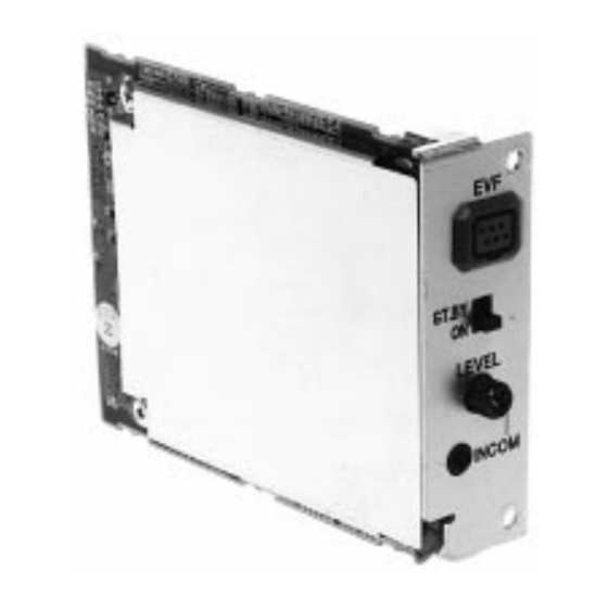
MAJOR OPERATING CONTROLS AND THEIR FUNCTIONS Viewfinder connector ST.BY Viewfinder standby switch LEVEL Intercom volume control INCOM Intercom connector q Viewfinder connector [EVF] Connect the cable for the viewfinder mounting bracket AW-Q40. w Viewfinder standby switch [ST.BY/ON] When this switch is set to [ST.BY], the viewfinder will be in standby condition. -
Page 7: Mounting
MOUNTING CAUTION • Be sure to ask your store, where you purchased the product, for mounting. • Disconnect the camera power connector before mounting. • Before handling the card, touch a metal part of the camera to discharge the static from the human body. - Page 8 P a n a s o n i c Rear Panel Option card slot cover Card setscrews (6 mm) P a n a s o n i c Rear panel setscrews (8 mm) Studio card...
-
Page 9: Connecting A Studio System
CONNECTING A STUDIO SYSTEM • To connect an RCU (WV-RC700A or WV-RC550) to the camera, use the RCU cable AW-CA50A26. • To mount the 5-inch electronic viewfinder WV-VF65C on the camera, use the viewfinder mounting bracket AW-Q40. • Power is supplied from the RCU. 5"... -
Page 10: Menu Item Setting
MENU ITEM SETTING A convertible camera, for example, AW-E300, can be set using the menu as suited to the system and shoot- ing conditions. For details, refer to the operation manu- al for the camera. Setup Procedures (Output Signal Selection) (1) Display the main menu. - Page 11 (2) The setting item (flashing) changes each time the menu switch, item switch, or NO switch is pressed. Select [Option Card Set] and press the YES switch to display the [Option Card Set] submenu. (3) Select an item to set using the menu switch and item switch.
- Page 12 Option Card Setting Submenu AW-PB301 **Opation Card Set** Zebra Indicator Zebra 1 Level Zebra 2 Level Safety Zone EVF Output Component Return q Zebra Indicator [Zebra Indicator: OFF/ON] ON: Zebra indicator is shown in the viewfinder. OFF: Zebra indicator is not shown in the viewfinder.
- Page 13 CVBS: Color signals are output to the viewfinder. No zebra indicator will be shown. t Component Output Select [Component Output: R/G/B, Y/Pr/Pb, Y/C] (AW-PB301 only) Component output signals can be selected. Component output signals are output from the inter- face/remote connector on the rear of the camera.
-
Page 14: Appearance
APPEARANCE mm (inch) 96 (3-3/4) 21.5 (27/32) 5 (3/16) 91 (2-3/4) ST.BY LEVEL INCOM -12-... -
Page 15: Specifications
(6.35 mm to 3.5 mm in diameter) ... 1 pc Y: 1.0 V[p-p], C: 0.286 V[p-p] 0.7 V[p-p] (AW-PB301 only) Y: 1.0 V[p-p], Pr/Pb: 0.7 V[p-p] (AW-PB301 only) 2.0 V[p-p] sync signal (AW-PB301 only) Screw (6 mm long) ... 2 pcs Screw (8 mm long) ... - Page 16 Broadcast & Television Systems Company Division of Matsushita Electric Corporation of America Executive Office: One Panasonic Way 3F-5, Secaucus, NJ 07094 Regional Offices: EASTERN ZONE: 50 Meadowlands Parkway, Secaucus, NJ 07094 (201) 348-7620 CENTRAL ZONE: 1707 North Randall Road, Elgin, IL 60123 (847) 468-5200...