beautypg.com
Manuals
Brands
Mitsubishi Electric Manuals
Controller
melsec q00ucpu
Mitsubishi Electric melsec q00ucpu Manuals
Manuals and User Guides for Mitsubishi Electric melsec q00ucpu. We have
2
Mitsubishi Electric melsec q00ucpu manuals available for free PDF download: User Manual
Mitsubishi Electric melsec q00ucpu User Manual (622 pages)
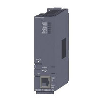
programmable controller
Brand:
Mitsubishi Electric
| Category:
Controller
| Size: 18.31 MB
Table of Contents
Safety Precautions
4
Revisions
12
Introduction
14
Table of Contents
15
Manuals
21
Manual Page Organization
23
Generic Terms and Abbreviations
24
Chapter1 Overview
26
Processing Order in the CPU Module
26
Storing and Executing Programs
27
Structured Programming
28
Devices and Instructions Useful for Programming
31
Features
36
Checking Serial Number and Function Version
38
Chapter2 Sequence Programs
40
Sequence Program Overview
40
Sequence Program Configuration
42
Main Routine Program
42
Main Routine Program
43
Subroutine Program
44
Settings When Program Is Divided
52
Initial Execution Type Program
56
Scan Execution Type Program
59
Stand-By Type Program
60
Fixed Scan Execution Type Program
65
Changing the Program Execution Type
69
Data Used in Sequence Programs
71
BIN (Binary Code)
74
HEX (Hexadecimal)
76
BCD (Binary-Coded Decimal)
77
Real Number (Floating-Point Data)
78
Character String Data
82
Chapter3 Cpu Module Operation
83
Initial Processing
83
I/O Refresh (Refresh Processing with Input/Output Modules)
84
Program Operation
84
END Processing
84
Operation Processing in the RUN,STOP, or PAUSE Status
85
Operation Processing During Momentary Power Failure
87
Data Clear Processing
88
I/O Processing and Response Delay
90
Refresh Mode
90
Refresh Mode
91
Direct Mode
94
Chapter4 Assignment Of Base Unit and I/Onumber
97
Base Unit Assignment
97
Base Mode
97
Base Unit Assignment Setting
98
I/O Number Assignment
100
Concept of I/O Number Assignment
101
Setting I/O Numbers
104
I/O Number Setting Example
109
Checking I/O Numbers
113
Chapter5 Memories And Files Used for Cpu Module
114
Memories Used for CPU Module
114
Memory Composition and Storable Data
114
Program Memory
118
Program Cache Memory
121
Standard ROM
124
Standard RAM
125
Memory Card
127
Writing to the Flash Card by GX Developer
131
Operating the Program in the Memory Card (Boot Operation)
136
Details of Written Files
140
Specifying Valid Parameters (Parameter-Valid Drive Setting)
141
Program File Structure
143
File Operations by GX Developer and Handling Precautions
145
File Operations
145
Precautions for Handling Files
146
File Size
147
Units of File Sizes
149
Chapter6 Functions
152
Function List
152
Constant Scan
155
Latch Function
158
Output Mode at Operating Status Change (STOP to RUN)
161
Clock Function
164
Remote Operation
168
Remote RUN/STOP
168
Remote PAUSE
168
Remote PAUSE
171
Remote RESET
173
Remote Latch Clear
175
Relationship between Remote Operation and RUN/STOP Status of the CPU Module
176
Q Series-Compatible Module Input Response Time Selection (I/O Response Time)
177
Error Time Output Mode Setting
179
H/W Error Time PLC Operation Mode Setting
180
Intelligent Function Module Switch Setting
181
Monitor Function
183
Monitor Condition Setting
184
Local Device Monitor/Test
190
External Input/Output Forced On/Off
193
Executional Conditioned Device Test
198
Writing Programs While CPU Module Is in RUN Status
209
Online Change (Files)
212
Precautions for Online Change
214
Execution Time Measurement
220
Interrupt Program Monitor List
223
Scan Time Measurement
224
Sampling Trace Function
228
Debug Funct(Ion from Multiple GX Developers
242
Write During RUN Function from Multiple GX Developers
244
Self-Diagnostic Function
248
Leds Indicating Errors
255
Error History
256
System Protection
257
Remote Password
259
System Display of CPU Module with GX Developer
264
LED Indication
267
LED Indication Priority
268
Interrupt from Intelligent Function Module
270
Serial Communication Function
271
Service Processing
279
Initial Device Value
286
Battery Life-Prolonging Function
290
Memory Check Function
291
Latch Data Backup to Standard ROM Function
292
Writing/Reading Device Data To/From Standard ROM
297
CPU Module Change Function with Memory Card
298
Backup Function to Memory Card
300
Backup Data Restoration Function
308
Chapter 7 Communications with Intelligent Function Module
312
Communications between CPU Module and Intelligent Function Module
312
Initial Setting and Auto Refresh Setting by GX Configurator
313
Initial Setting by Initial Device Value
316
Communications Using the Intelligent Function Module Device
317
Communications Using the Intelligent Function Module Dedicated Instruction
319
Chapter 8 Parameters
322
PLC Parameters
322
Network Parameters
340
Remote Password
345
Chapter 9 Devices
346
Device List
346
Internal User Device
348
Input (X)
351
Output (Y)
353
Internal Relay (M)
354
Latch Relay (L)
355
Annunciator (F)
356
Edge Relay (V)
360
Link Relay (B)
361
Link Special Relay (SB)
363
Step Relay (S)
364
Timer (T)
365
Counter (C)
372
Data Register (D)
376
Link Register (W)
377
Link Special Register (SW)
379
Internal System Devices
380
Special Relay (SM)
383
Special Register (SD)
384
Link Direct Device (J\)
385
Module Access Devices
388
Cyclic Transmission Area Device (U3En\G)
390
Index Register (Z)/Standard Device Resister (Z)
391
Standard Device Register (Z)
393
Type Program
394
File Register (R)
398
File Register Data Storage Location
399
Differences in Available Accesses by Storage Memory
400
Registration Procedure for the File Register
401
Specification Methods of the File Register
406
Precautions for Using the File Register
407
Extended Data Register (D) and Extended Link Register (W)
409
Nesting (N)
415
Pointer (P)
416
Local Pointer
417
Common Pointer
419
Interrupt Pointer(I)
421
List of Interrupt Pointer Numbers and Interrupt Factors
422
Other Devices
423
I/O No. Specification Device (U)
424
Macro Instruction Argument Device (VD)
425
Constants
426
Real Number (E)
427
Character String (" ")
428
Convenient Usage of Devices
429
Local Device
430
Chapter 10 Cpu Module Processing Time
440
Scan Time
440
Time Required for each Processing Included in Scan Time
441
Factors that Increase the Scan Time
450
CHAPTER 11 PROCEDURES for WRITING PROGRAM to CPU MODULE11-1 to 11-10
457
Items to be Considered for Creating Programs
457
Hardware Check
459
Procedure for Writing One Program
461
Procedure for Writing Multiple Programs
463
Procedure for Boot Operation
466
Appendix 1 List of Parameter Numbers
545
CHAPTER 12 SPECIAL RELAY LIST and SPECIAL REGISTER LIST 12-1 to 12-78
545
Appendix 2 Functions Added or Changed by Version Upgrade
550
Appendix 3 Method of Replacing Basic Model QCPU or High Performance Model QCPU with Universal Model QCPU
552
Appendix 3.1.1 Replacing Basic Model QCPU with Universal Model QCPU
556
Appendix 3.1 Precautions for Replacement
556
Appendix 3.1.2 Replacing High Performance Model QCPU with Universal Model QCPU
556
Appendix 3.2 Applicable Devices and Software
563
Appendix 3.3 Instructions
567
Appendix 3.3.1 Instructions Not Supported in the Universal Model QCPU and Replacing
570
Appendix 3.3.2 Replacing Programs Using Multiple CPU Transmission Dedicated Instructions
570
Appendix 3.3.3 Program Replacement Examples
570
Appendix 3.4 Functions
584
Appendix 3.4.1 Floating-Point Operation Instructions
592
Appendix 3.4.2 Error Check Processing for Floating-Point Data Comparison Instructions
592
Appendix 3.4.3 Device Latch Function
596
Appendix 3.4.4 File Usability Setting
598
Appendix 3.4.5 Parameter-Valid Drive and Boot File Setting
608
Appendix 3.4.6 External Input/Output Forced On/Off Function
608
Appendix 3.5 Special Relay and Special Register
608
Appendix 3.5.1 Special Relay List
613
Appendix 3.5.2 Special Register List
613
Appendix 4 Device Point Assignment Sheet
613
Mitsubishi Electric melsec q00ucpu User Manual (270 pages)
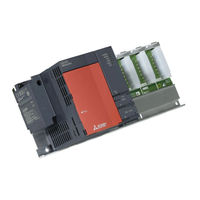
Programmable Controller Multiple CPU System
Brand:
Mitsubishi Electric
| Category:
Processor
| Size: 7.75 MB
Table of Contents
Safety Precautions
4
Installation Precautions
7
Revisions
12
Introduction
14
Table of Contents
15
Manuals
18
Manual Page Organization
21
Generic Terms and Abbreviations
23
Chapter 1 Outline
26
What Is Multiple CPU System?
26
Features of Multiple CPU System
30
Difference from Single CPU System
36
Chapter 2 System Configuration
49
System Configuration
49
System Configuration Using Basic Model QCPU (Q00CPU, Q01CPU)
49
CPU No.1
58
System Configuration Using Universal Model QCPU as CPU No.1
72
Configuration of Peripheral Devices
86
Configurable Device and Available Software
90
Precautions for System Configuration
100
Chapter 3 Concept for Multiple Cpu System
106
Mounting Position of CPU Module
106
When CPU No.1 Is Basic Model QCPU
107
When CPU No.1 Is High Performance Model QCPU or Process CPU
111
When CPU No.1 Is Universal Model QCPU
116
CPU No. of CPU Module
123
Concept of I/O Number Assignment
125
I/O Number Assignment of each Module
125
I/O Number of each CPU Module
127
Access Range of CPU Module and Other Modules
128
Access Range with Controlled Module
128
Access Range with Non-Controlled Module
128
Access Target under GOT Connection
135
Access with Instruction Using Link Direct Device
135
Access Range of GX Developer
136
Clock Data Used by CPU Module and Intelligent Function Module
139
Clock Data Used by Intelligent Function Module
140
Resetting the Multiple CPU System
141
Operation for CPU Module Stop Error
142
Host CPU Number of Multiple CPU System
145
Chapter4 Communications Between Cpu Modules
147
Communications between CPU Modules Using CPU Shared Memory
149
CPU Shared Memory
149
Communication by Auto Refresh Using CPU Shared Memory
154
Communication by Auto Refresh Using Multiple CPU High Speed Transmission Area
169
Communication Using CPU Shared Memory by Program
182
Communications between CPU Modules When the Error Occurs
192
Communications with Instructions Dedicated to Motion CPU
193
Control Instruction from QCPU to Motion CPU
193
Communication with Dedicated Instructions
195
Writing/Reading of Device Data from QCPU to Motion CPU
195
Writing/Reading of Device Data from QCPU to QCPU
198
Multiple CPU Synchronous Interrupt
199
Multiple CPU Synchronized Boot-Up
201
CHAPTER5 PROCESSING TIME of QCPU in MULTIPLE CPU SYSTEM 5-1 to
203
Concept of Scan Time
203
Factors for Prolonged Scan Time
205
Reducing Processing Time
212
Chapter6 Parameter Added for Multiple Cpu System
213
Parameter List
213
Number of Cpus Setting
218
Operating Mode Setting
220
Online Module Change Setting
220
I/O Settings Outside of the Group
220
Communication Area Setting (Refresh Setting)
220
Control CPU Settings
221
Multiple CPU Synchronized Boot-Up
221
Multiple CPU High Speed Transmission Area Setting
221
CHAPTER7 PRECAUTIONS FOR USING Ans/A SERIES-COMPATIBLE MODULES
222
Precautions for Use of Ans/A Series Compatible Module
222
Chapter8 Starting Up the Multiple Cpu System
226
Flow-Chart for Starting up the Multiple CPU System
226
Setting up the Multiple CPU System Parameters
228
Process CPU
228
Parameter Setting for the Universal Model QCPU
240
Reusing Preset Multiple CPU Parameters
248
Communication Program Examples Using Auto Refresh
253
Process CPU
253
Program Examples for the Universal Model QCPU
259
Related Products
Mitsubishi Electric melsec q00ujcpu
Mitsubishi Electric Q00(J)CPU
Mitsubishi Electric melsec q02ucpu
Mitsubishi Electric melsec q03ud(E)cpu
Mitsubishi Electric Q02PHCPU
Mitsubishi Electric Q06PHCPU
Mitsubishi Electric Q04UDVCPU
Mitsubishi Electric Q02HCPU-A
Mitsubishi Electric Q06HCPU-A
Mitsubishi Electric Q06UDVCPU
Mitsubishi Electric Categories
Air Conditioner
Controller
Projector
Inverter
Heat Pump
More Mitsubishi Electric Manuals